
Related Manuals for Flowserve F5


Summary of Contents for Flowserve F5
- Page 1 USER INSTRUCTIONS Installation F5 Switch Box Operation PMENIM0005-05-A5 02/19 Maintenance...
-
Page 2: Table Of Contents
3. Mounting on P5 or EP5 4. Mounting on P-2000/P-2020 5. Installing F5-EX on P5/EP5 6. Installing on an actuator 7. Calibration 8. Switches & Sensors 9. Connection of F5 intrinsically safe version 10. Spare Parts 11. Dimension drawing 12. Trouble shooting... -
Page 3: Introduction
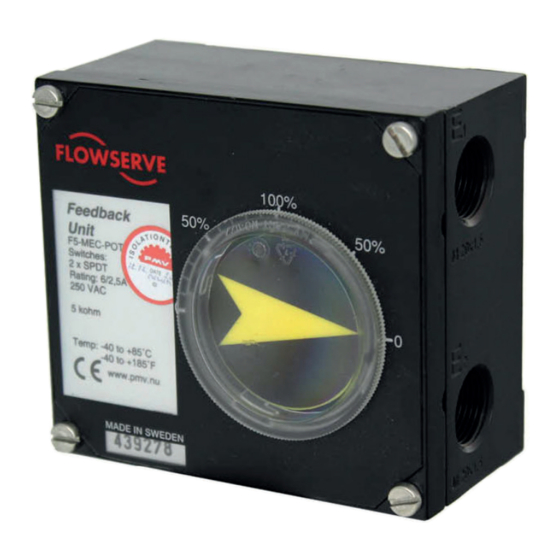
PMENIM0005-05-A5 02/19 1. Introduction The PMV F5 is a feedback unit uniquely designed to mount on top of the PMV P5, EP5 or P-2000 positioners with minimum parts required. The F5 can also be mounted on actuators with an additional mounting kit. The F5 is available in two different enclosures, standard or explosion proof. - Page 4 Warning! Special Conditions for Safe Use The enclosure of PMV F5 Intrinsically Safe version is made of aluminum and any impact or friction caused by external objects shall be avoided in the application. The various circuits of the electrical apparatus must only be connected to intrinsically safe certified electrical apparatus, and these combinations must be compatible with the rules of intrinsic safety.
- Page 5 EEx ia IIC T4 Cl.I Div1 Groups C-D T3C Electrical rating: 28V DC, 24mA When installed in accordance with installation drawing: F5-2-4-9516 WARNING! Substitution of components may impair intrinsic safety. AVERTISSEMENT! La substitution de composants peut compromettre la securite intrinseque.
-
Page 6: Storage
For further assistance, please contact you nearest PMV office. Storage Seal F5 is supplied with conduit entry points sealed. The seal is only a storage seal, not to be used as seal when F5 is in operation. -
Page 7: Mounting On P5 Or Ep5
– Install drive coupling (4) on the positioner shaft, secure it with screw (3) – Check that F5 is fitted with 4 nos of screws (5) and O-ring (9), install the F5 on top of the positioner unit, make sure that the coupling is properly engaged before tightening the four screws (5) –... -
Page 8: Mounting On P-2000/P-2020
– Check that the gasket is fitted to the bottom of plate (2), install screws (5) (3x long, 1x short) plastic washer (6) and O-rings (7). – Secure the F5 to the plate (2) with screws (3). – Install assembly on to the positioner, make sure that coupling (1) is properly engaged. -
Page 9: Installing F5-Ex On
6. Installing on an actuator – Remove front covers and indicator from the F5-EX unit. – Install drive shaft into F5-EX, a solid click should be heard when spindle adapter is properly installed. – Mount F5-EX on the actuator using the F05 holes and a mounting kit. - Page 10 (2) and cams (3) to desired position using tool F5-22 or tip of a screw driver that fits snuggly in one of the slotted holes. Start calibration procedure by adjusting position transmitter first, then continue with the lower switch and complete with the upper switch.
-
Page 11: Calibration
3 to desired position by rotating it with special tool F5-22 or by the tip of a screw driver placed in one of the slotted holes on the cam. - Page 12 4. Adjust the potentiometer output reading to approx. 50 Ohm by rotating gear wheel 2 with special tool F5-22 or tip of a screw driver placed in one of the slotted holes. 5. Stroke the actuator to desired maximum resistance position and check reading.
-
Page 13: Connection Of F5 Intrinsically Safe Version
F5 Switch Box PMENIM0005-05-A5 02/19 9. Connection of F5 intrinsically safe version... -
Page 14: Spare Parts
Cam & shaft assy for Mechanical switches or Namur sensors + transmitter 29276 Cam & shaft assy for Proximity switches + transmitter F5-SEAL-NBR Elastomer kil, itrile NBR F5-SCREWS Screw kil F5 F5-AS2-PV90 Fron cover assembly incl.flat indicator F5-SP22 Coupling F5-S00 and Adjusting Tool FS-22... -
Page 15: Dimension Drawing
F5 Switch Box PMENIM0005-05-A5 02/19 11. Dimension drawing... -
Page 16: Trouble Shooting
F5 Switch Box PMENIM0005-05-A5 02/19 12. Trouble shooting Switches Check electrical connections and cam settings. Potentiometer If there is no output signal, check electrical connec- tions and for open circuit, check that potentio- meter is not out of it’s mechanical range. - Page 17 Flowserve products. ’The purchaser/user should read and understand the user instructions includ- Beijing, China 100004 ed with the product, and train its employees and contractors in the safe use of Flowserve products in connection Phone: +86 10 6561 1900 with the specific application.
Need help?
Do you have a question about the F5 and is the answer not in the manual?
Questions and answers