
Related Manuals for Flowserve UltraSwitch PMV DS


Summary of Contents for Flowserve UltraSwitch PMV DS
- Page 1 USER INSTRUCTIONS PMV DS/DM Ultraswitch™ Installation Switch box Operation Maintenance FCD PMENIM0020-03-A5 - 05/19 Experience In Motion...
-
Page 2: Table Of Contents
FCD PMENIM0020-03-A5 - 05/19 CONTENTS 1. GENERAL INFORMATION ........................3 2. SAFETY INSTRUCTION ..........................3 General safety...............................3 Specific Conditions of Use ..........................3 3. UNPACKING .............................3 4. CERTIFICATES ............................4 5. SPECIFICATIONS .............................4 5.1 Technical data............................4 5.2 Materials of construction ........................4 5.3 Product lable example ..........................4 5.4 DS/DM UltraSwitch™... -
Page 3: General Information
• Pay attention to personal protection, (clothing, glas- atmospheres , disconnect power before servicing. ses, gloves) when performing installation or service. • Use only Flowserve original spare parts in order not to • Use only Flowserve original spare parts to avoid invalidate certification. -
Page 4: Certificates
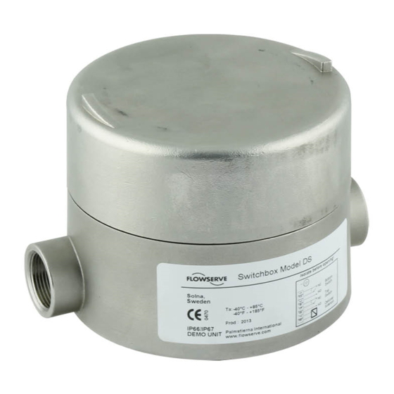
FCD PMENIM0020-03-A5 - 05/19 4. CERTIFICATES All certificates available for download at www.pmv.nu 5. SPECIFICATIONS 5.1 TECHNICAL DATA Enclosure ratings IP66, IEC 529 Weight Aluminum housing 1.8kg / 4 lbs Weight Stainless Steel housing 3.5kg / 7.75 lbs Working Temperature: -55°C to +85°C / -67°F to +185°F for General Purpose units For certified units please see each certificate respectively Maximum Surface Temperature:... -
Page 5: Ds/Dm Ultraswitch™ Nomenclature
FCD PMENIM0020-03-A5 - 05/19 5.4 DS/DM ULTRASWITCH™ NOMENCLATURE Product and Connections (cable entry) Explosion Proof / Flame proof switch box with 3/4” NPT cable entries Explosion Proof / Flame proof switch box with M25x1,5 cable entries Number of open cable entries 2 x open cable entries (option) 3 x open cable entries (standard) Housing material /Surface treatment... -
Page 6: Ds/Dm Ultraswitch™ Switch Options
0.35A at 140 VAC / .25A at 200VDC (50 W Max.) P5 SPDT Proximity Hamlin 59135-030 0.25A at 120 VAC / 0.25A at 28 VDC (3 W Max.) PE SPDT Sabre Proximity Flowserve XA0199 1A at 120 VAC / 1A at 24 VDC PP SPDT Phazer Proximity Flowserve XA0155... -
Page 7: Installation
FCD PMENIM0020-03-A5 - 05/19 6. INSTALLATION A variety of mounting hardware is available for mounting the DS/DM Ultraswitch™ to valve actuators. For best results, specify the NAMUR shaft option and NAMUR mounting hardware when installing to NAMUR NOTE: If the equipment is likely to come into contact compliant actuator. -
Page 8: Wiring Instructions
FCD PMENIM0020-03-A5 - 05/19 6.1 WIRING INSTRUCTIONS DS/DM UltraSwitch™ enclosures feature pre-wired switches. All user connections are made at a numbered terminal strip. Both external and internal grounding locations have been provided for use in installation (see illustration to the right). A wiring dia- gram is located inside the cover and indicates which terminal numbers correspond to switch contacts: normally open, normally closed, common, etc. -
Page 9: Switches (Certified)
FCD PMENIM0020-03-A5 - 05/19 7. SWITCHES (CERTIFIED) Substitution of components may impair suitability for hazardous (classified) locations. Do not dis- connect equipment unless area is known to be non-hazardous. To prevent ignition of flammable or combustible atmospheres, disconnect power before servicing. 7.1 INSTALLATION IN HAZARDOUS LOCATIONS Installation of this device may only be performed by authorized personnel. -
Page 10: Cam Fine Adjustment
FCD PMENIM0020-03-A5 - 05/19 7.3 CAM FINE ADJUSTMENT Some cams have a fine adjustment available. These cams will have a small screw embedded into the side of the cam. Adjusting this screw clockwise or counter clockwise will deform the cam, changing the trip point slightly. Cam fine adjustment 7.4 ADJUSTING VISUAL POSITION INDICATOR (OPTIONAL PART):... -
Page 11: Calibrating 4-20 Ma Transmitter
FCD PMENIM0020-03-A5 - 05/19 7.7 CALIBRATING 4-20 MA TRANSMITTER Adjust feedback board span trim pot to yield 20 mA. (Turning CW increases value, turning CCW Setting direct/reverse action: A dip-switch setting decreases value). controls the direction of increasing travel. For 4 mA in the full clockwise position, select ”D”, for 4 mA in the The zero and span adjustments are interactive. -
Page 12: Dimensions (Mm/Inch)
FCD PMENIM0020-03-A5 - 05/19 8. DIMENSIONS (MM/INCH) 35,4 (1.394) 57,2 (2.252) 3/4"-14 NPT OR M25X1.5 (1-3x) 149 (5.866) 56 (2.203) SHAFTS NAF TURNEX DOUBLE "D" 1/4" NAMUR "D" WITH NUT VDI/VDE 3845 LINEAR... -
Page 13: Notes
FCD PMENIM0020-03-A5 - 05/19 9. NOTES... - Page 14 FCD PMENIM0020-03-A5 - 05/19 9. NOTES (CONTINUED)
- Page 15 FCD PMENIM0020-03-A5 - 05/19 9. NOTES (CONTINUED)
- Page 16 When properly selected, this Flowserve product is designed to perform its intended function E-mail: salespmv@flowserve.com safely during its useful life. However, the purchaser or user of Flowserve products should be aware that Flowserve products might be used in numerous applications under a wide variety of industrial Asia Pacific Headquarters service conditions.
Need help?
Do you have a question about the UltraSwitch PMV DS and is the answer not in the manual?
Questions and answers