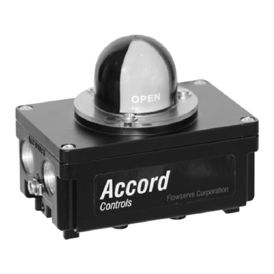
Summary of Contents for Flowserve Accord WS/WM Ultraswitch
- Page 1 USER INSTRUCTIONS Accord WS/WM Ultraswitch™ Installation Switchbox Operation Maintenance FCD ACENIM0135-02 - 09/16...
-
Page 2: Table Of Contents
FCD ACENIM0135-02 - 09/16 CONTENTS 1. GENERAL INFORMATION ..................3 2. SAFETY INSTRUCTION ..................3 3. UNPACKING ....................3 4. CERTIFICATES ....................4 5. SPECIFICATIONS ....................4 5.1 Technical data ..........................4 5.2 Materials of construction ........................ 4 5.3 Product label ........................... 4 5.4 WS/WM UltraSwitch™... -
Page 3: General Information
• To prevent ignition of flammable or combustible • All grounding and bonding installation requirements atmospheres, disconnect power before servicing. must be addressed. • Use only Flowserve original spare parts in order not to invalidate certification. WARNING POTENTIAL ELECTROSTATIC HAZARD DO NOT OPEN WHEN AN EXPLOSIVE ATMOSPHERE MAY BE PRESENT CABLE ENTRANCES MAY REACH A TEMPERATURE OF MAX 83 ºC... -
Page 4: Certificates
FCD ACENIM0135-02 - 09/16 4. CERTIFICATES General Purpose ATEX II 1GD Ex ia IIC T4/T5/T6 ATEX II 1GD Ex ia IIB T4/T5/T6 cCSAus Class I, Division 1 Groups A,B,C,D; Class II Division 1 Groups F,G; Class III cCSAus Class I, Division 2, Groups A,B,C,D; Class II, Division 2, Groups F,G; Class III 5. -
Page 5: Ws/Wm Ultraswitch™ Nomenclature
FCD ACENIM0135-02 - 09/16 5.4 WS/WM UltraSwitch™ nomenclature Brand sticker Accord Shaft type Namur shaft, EN 15714 Low profile shaft For NAF Turnex Double ”D” 1/4 Inch Flats Body style General Purpose/I.S. Enclosure / 1/2” NPT Conduit entries General Purpose/I.S. Enclosure / M20x1,5mm Conduit entries Number of conduit entries 2 conduit entries 4 conduit entries (2 according to ”C”... -
Page 6: Ws/Wm Ultraswitch™ Switch Options
Hamlin 0.25A @ 120 VAC; 0.25A @ 28 VDC (3 W Max.) A, B, C SPDT Sabre Proximity Flowserve 1A @ 120 VAC; 1A @ 24 VDC SPDT Phazer Proximity Flowserve 3A @ 120 VAC; 2A @ 24 VDC A, B, C... - Page 7 FCD ACENIM0135-02 - 09/16 Code Certificate ATEX II 1GD Ex ia IIC T4/T5/T6 ATEX II 1GD Ex ia IIB T4/T5/T6 cCSAus IS cCSAus NI Notes 1) Valid certification codes according to table in WS/WM Nomenclature on page 5. 2) Some models have more than two open terminal locations open as standard. Consult factory for details.
-
Page 8: Installation
FCD ACENIM0135-02 - 09/16 6. INSTALLATION The WS/WM Ultraswitch™ may be installed to valves or valve actuators with a variety of mounting hardware. For best results, specify the NAMUR shaft option and NAMUR mounting hardware when fitting to a NAMUR compliant actuator. These options allow direct coupling to actuators without couplings, reducing dead band. -
Page 9: Wiring Instructions
FCD ACENIM0135-02 - 09/16 6.1 Wiring instructions • Perform all wiring according to the Internal and external grounding wiring diagram found on the label in the housing (see picture) and instructions given below. • Make sure that the ground wire is correctly connected •... -
Page 10: Cover And Housing Options
FCD ACENIM0135-02 - 09/16 6.2 Cover and housing options Aluminum or Resin Aluminum or Resin Aluminum or Resin cover cover flat cover Dome Indicator Arrow Indicator Polycarbonate transparent cover Polycarbonate transparent cover Dome Indicator Arrow Indicator Aluminum housing Resin housing... -
Page 11: Switches (Certified)
FCD ACENIM0135-02 - 09/16 7. Switches (certified) Substitution of components may impair suitability for hazardous (classified) locations. Do not disconnect equipment unless area is known to be non-hazardous. To prevent ignition of flammable or combustible atmospheres, disconnect power before ser- vicing, or;... -
Page 12: Switch Option Specifications (All)
FCD ACENIM0135-02 - 09/16 7.5 Switch option specifications (all) Code Switch Option Manufacturer Part Number Load Capacity No switches (empty housing) IN5129 10-36VDC (J=14only) IF5250 10-36VDC NC PNP, 150mA, 3-wire NC IF6001 18-32VDC, NO PNP, 150mA@50°C IF6034 10-36VDC, NO PNP, 150mA, Stainless Steel IN0074 20-250 AC/DC NO, 350mA/100mA IN0081... - Page 13 (50 W Max.) SPDT Proximity Hamlin 59135-030 0.25A at 120 VAC / 0.25A at 28 VDC (3 W Max.) SPDT Sabre Pxy Flowserve XA0199 1A at 120 VAC / 1A at 24 VDC SPDT Phazer Pxy Flowserve XA0155 3A at 120 VAC / 2A at 24 VDC...
-
Page 14: Dimensions
FCD ACENIM0135-02 - 09/16 8. Dimensions WS body enclosure WM body enclosure... -
Page 15: Spare Parts
FCD ACENIM0135-02 - 09/16 9. Spare parts Pos Part No Description D2-SP31 Arrow indicator assembly D2-SP52 Dome indicator assembly red/green D2-SP17 Dome indicator assembly black/yellow M800214 Polycarbonate transparent cover with dome indicator red/green M800215 Polycarbonate transparent cover with arrow indicator ME1967 Gasket for cover (all cover types) - Page 16 Should any question arise concerning these provisions, the purchaser/user should product is designed to perform its intended function safely during its useful life. However, the purchaser or user of Flowserve products should be aware that Flowserve products might be used in numerous applications under a wide variety of industrial service conditions. Although Flowserve can provide Fax: +65 6862 4940 contact Flowserve Corporation at any one of its worldwide operations or offices.


Need help?
Do you have a question about the Accord WS/WM Ultraswitch and is the answer not in the manual?
Questions and answers