Subscribe to Our Youtube Channel
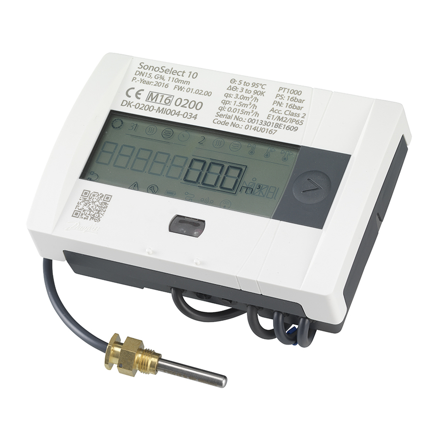
Summary of Contents for Danfoss SonoSelect
- Page 1 Installation guide SonoSelect and SonoSafe Energy Meters www.heating.danfoss.com 09/2017 VU.IG.B9.02 © Danfoss...
- Page 2 Installation guide SonoSelect and SonoSafe Product category: Energy Meters Type designation(s): SonoSelect 10 and SonoSafe 10 Note: To ensure latest version of declaration, please visit danfoss.com. 2 | © Danfoss | Energy Meters | 2019.03 VU.IG.B9.02...
-
Page 3: Table Of Contents
Disposal................18 VU.IG.B9.02 © Danfoss | Energy Meters | 2019.03 | 3... -
Page 4: General
-25 - 60 °C Temperature media 5 - 95 °C 3.6 V DC lithium battery (2 AA SonoSelect 1 AA SonoSafe), Mains supply Power supply 230V AC +10/-15 % 50/60 Hz, battery back up in case of power cuts: 1 hour... -
Page 5: Identification Of Installation: Supply/Return Pipe Installation
Rotation in pipe axis: Flow sensor should be angled in 45 can be collected. to 315° to avoid air collection in flow sensor. 2.4 Mounting orientation, calculator 4 x 90° VU.IG.B9.02 © Danfoss | Energy Meters | 2019.03 | 5... -
Page 6: Mounting Of O-Ring And Temperature Sensor
30.5 mm G1¼ 39mm Note: • Tolerance on machined dimensions = ± 0.5 mm. • Pipe fittings for use with probe type DS (Direct Short). : Provision for security sealing. 6 | © Danfoss | Energy Meters | 2019.03 VU.IG.B9.02... -
Page 7: Bifunctional Meters
ΔΘhc = ΔΘcutoff = 0.25K 2.7 Communication modules Modules in general To adapt the meter for various applications SonoSelect 10 and SonoSafe 10 features a slot for mounting communication modules. Each module features its own µ-controller. Modules have their own parameter set which is saved in the module µ-controller flash memory. A local copy of the energy meter parameters used for communication is stored in the module. - Page 8 ≤ 5 Hz Pulse inputs According to EN1434-2, section 7.1.5 (Classification of pulse input devices Class IB) Battery life time 16+1 year * Suitable for both electronic switch and Reed contact. 8 | © Danfoss | Energy Meters | 2019.03 VU.IG.B9.02...
- Page 9 • Month log 1 (last month log) • Difference temperature • CurrentTime • Enclosure temperature • Current time • Hour counter factory • Hour counter OK * Can be changed via SonoApp VU.IG.B9.02 © Danfoss | Energy Meters | 2019.03 | 9...
- Page 10 Mains power meters are delivered with M12x1.5 cable gland suitable for outside cable Mains power cable diameter Ø3-Ø6.5mm 2x0.75 mm . In case stranded wire is used Ferrules are required. Pre fuse of max 6A must be used 10 | © Danfoss | Energy Meters | 2019.03 VU.IG.B9.02...
-
Page 11: Installation Of Module/Cable
SonoApp user guide. terminals matching colour and terminal numbers. Fix cable(s) to cable relief. Outer jacket no longer than 9 mm from cable relief (line). Press down. VU.IG.B9.02 © Danfoss | Energy Meters | 2019.03 | 11... -
Page 12: Battery
Use SonoApp to set date/time and confirm parts. battery change (and reset tamper alarm E13 for SonoSelect). If no Sonoapp is available a long press of 5 seconds when display shown “use app” will also confirm the battery change. Note that date and time will not be updated. -
Page 13: Mains Supply
5. Insert cable through cable gland hole to secure 6. Connect cable and fix it to screw terminals. IP class and strain relief. In case stranded wire is Tighten the cable gland. used Ferrules are required. VU.IG.B9.02 © Danfoss | Energy Meters | 2019.03 | 13... - Page 14 1) Use SonoApp to set up confirm mains supply parts. Power up the meter. and set date & time 2) Hold button for 5 seconds to continue without setting date & time 14 | © Danfoss | Energy Meters | 2019.03 VU.IG.B9.02...
-
Page 15: Commissioning
Make sure no error codes are displayed. Check the display for a plausible indication of flow rate and temperatures. For SonoSelect: Run installation check using Bluetooth dongle 014U1963 and SonoApp service tool. 3.2 Supply/return configuration Only available for SonoSelect: Use Bluetooth dongle 014U1963 and SonoApp service tool/Configuration. -
Page 16: Function Overview
Bifunctional heat/cool: energy heat, volume heat, energy cool, volume heat Current Supply temp. Return temp. Display test/All on Power Flow LOOP 2 click History log Accounting date Monthly date 1 >> Monthly date 12 LOOP 3 click 16 | © Danfoss | Energy Meters | 2019.03 VU.IG.B9.02... -
Page 17: Display Explanation
High flow > qss Supply Temperature Error Battery consumption too high Return Temperature Error Display overflow (energy/volume) Bifunctional meter dead band error Absolute/Difference temperature outside accumulated range Communication module error Low transducer signal VU.IG.B9.02 © Danfoss | Energy Meters | 2019.03 | 17... -
Page 18: Device Overview
Flow sensor (including Brass, stainless steel, PPS Metal recovery transducer and liner) Transducer PZT, stainless steel, PEI Approved deposit for PZT Other plastic parts PC, PPS, PEI, TPE Plastic recovery 18 | © Danfoss | Energy Meters | 2019.03 VU.IG.B9.02... - Page 19 Installation guide SonoSelect and SonoSafe VU.IG.B9.02 © Danfoss | Energy Meters | 2019.03 | 19...
- Page 20 Heating Segment • heating.danfoss.com • +45 7488 2222 • E-Mail: heating@danfoss.com Danfoss can accept no responsibility for possible errors in catalogues, brochures and other printed material. Danfoss reserves the right to alter its products without notice. This also applies to products already on order provided that such alterations can be made without subsequential changes being necessary in speci cations already agreed.


Need help?
Do you have a question about the SonoSelect and is the answer not in the manual?
Questions and answers