
Subscribe to Our Youtube Channel
Related Manuals for rotork Mk3


Summary of Contents for rotork Mk3
- Page 1 Mk3 Foundation Fieldbus Option Card Technical Manual Publication PUB089-005-00_0618...
- Page 2 Foundation is a registered trademark of the Fieldbus Foundation. NI-FBUS is a registered trademark of National Instruments. Windows is a registered trademark of The Microsoft Corporation. The names; Allen, Bluetooth, Modbus, Rotork and Torx are registered trademarks. 2 of 116 Publication PUB089-005-00_0618...
-
Page 3: Table Of Contents
INTRODUCTION ....................9 FF CARD PROPERTIES ................. 11 Mechanical properties ......................11 Electrical properties ......................12 Operation and storage .......................12 FITTING THE FF CP CARD ................13 Inside a Rotork Actuator ....................13 3.1.1 Inside an IQ3/IQT3 actuator ................13 3.1.2 Inside an SI actuator ..................15 3.1.3... - Page 4 Foundation Fieldbus CP Option Card Technical Manual FUNCTION BLOCKS ..................43 Resource Block ........................44 Transducer Block .......................47 6.2.1 Transducer block parameters ................47 6.2.2 Changing the settings in the Transducer block..........53 6.2.3 Editing the Foundation specific parameters 1-23 and 99 ........54 6.2.4 Editing the actuator setup parameters 50-67 .............54 6.2.5...
- Page 5 Contents APPENDIX A – HANDLING FAULT CONDITIONS..........91 APPENDIX B – FUNCTION BLOCK MODE – LO ........... 92 APPENDIX C – PID APPLICATION................ 93 APPENDIX D – ITK6 FF SPECIFICATION DATASHEET ........96 Basic Fieldbus Function Blocks ..................96 Channel Allocation ......................96 Segment Information ......................97 APPENDIX E –...
-
Page 6: Glossary Of Terms
Foundation Fieldbus CP Option Card Technical Manual Glossary of Terms: Automatic (AUTO) A possible mode of a function block which means the block runs its algorithms, producing data at its inputs or outputs. Basic Device A basic device is any device not having the capability to control communications on an H1 fieldbus segment. - Page 7 Contents Local Override (LO) A possible mode of a function block where the block can only be monitored, and no changes can occur to its set points. Manual (MAN) A possible mode of a function block where the final element is manually input by a user, as opposed to being controlled by its algorithms.
-
Page 8: Abbreviations Used
Foundation Fieldbus CP Option Card Technical Manual Abbreviations used: Analogue Input (Blocks AI1, AI2) Analogue Output (Block A0) BTST Bluetooth Setting Tool Common File Format Comms Communications Common Protocol Control Selector Block Distributed Control System Device Description Digital Input (Blocks DI1, DI2, DI3, DI4, DI5) Digital Output (Blocks DO1, DO2, DO3, DO4) (Actuator) Digital Switch Mechanism Device Type Manager... -
Page 9: Introduction
FF nodes to function. The current version of the FF card may be fitted into any of the current Rotork Controls’ actuator product range. The FF card is an integral part of the actuator in which it is housed and is fitted within the main electrical housing. - Page 10 Foundation Fieldbus CP Option Card Technical Manual General The FF CP card is capable of performing the following functions:– Link Master / Link Active Scheduler Basic Device The in-built function blocks vary in availability between the different actuator types. The input and output blocks are used to link to the transducer block and tie to the available actuator functions.
-
Page 11: Ff Card Properties
FF CP Card Properties FF CARD PROPERTIES Mechanical properties The FF CP card consists of a single network interface card that fits directly to the main actuator control PCB. It consists of two isolated parts, the actuator interface and the network interface ... -
Page 12: Electrical Properties
Foundation Fieldbus CP Option Card Technical Manual Electrical properties The FF CP card does not sit in the main control path for the actuator and does not affect the actuator control integrity. Internally stored programs control the processors on the module. The Network Interface processor software may be updated by connecting a suitable test cable and loading the new code directly, but this cannot be done in the field The FF system allows all settings for the data highway and module communication functions to be held in non-volatile memory on the Network Interface Card. -
Page 13: Fitting The Ff Cp Card
Fitting the FF CP card FITTING THE FF CP CARD Inside a Rotork Actuator 3.1.1 Inside an IQ3/IQT3 actuator The FF CP card is suitable for fitting into IQ3 actuators. When factory-fitted, their wiring diagrams will contain an ‘F’, e.g. 100F2000. The FF CP can be located in one of 2 or 4 option ‘slots’ located on the back of the control module PCB, housed in the electrical cover. - Page 14 Some FF TB parameters can be set and adjusted either by using the Infra-red and Bluetooth setting tools or by Insight 2 using Bluetooth. The parameter setting procedure is covered by the IQ3 Full configuration, status and monitoring user manual, PUB002-040-00, available on the Rotork web site, www.rotork.com...
-
Page 15: Inside An Si Actuator
Fitting the FF CP card 3.1.2 Inside an SI actuator The FF CP is suitable for fitting into SI actuators. When factory-fitted, the network connections will be as in the diagram below: Fig 3.2: The SI highway interface connection table The internal layout of the actuator will be similar to that of the IQ3, when considering installation of the FF CP, as above. -
Page 16: Inside A Cva Actuator
FFs or if a replacement card is fitted. To enable the card, the Rotork PDA software Enlight (downloadable from the Rotork web site) is required to be used to change parameter 34. It must be read and then have 2048 decimal added to it. -
Page 17: Inside A Cma Actuator
The CMA actuator will need configuring, so that it is aware that control from the field is through the FF CP card. This is done by accessing the menu structure as shown in the CMA Installation and Maintenance manual, PUB094-003, found on the Rotork web site. Publication PUB089-005-00_0618... -
Page 18: Inside A K Range Actuator
Foundation Fieldbus CP Option Card Technical Manual 3.1.5 Inside a K range actuator The FF CP is suitable for fitting into K-Range actuators; wiring diagrams similar to 1612ZFD detail the option card connections. The FF CP module is fitted in the only option board slot inside the K-Range electrical housing. -
Page 19: Inside A Ck Actuator
Fitting the FF CP card 3.1.6 Inside a CK actuator The FF CP card is suitable for fitting into CK / CK actuators with Px5xxxxx and Kx5xxxxx series wiring diagrams. The connections and fitting in a CK are the same as the CK so the following information effectively relates to both actuator types. -
Page 20: Replacing Or Fitting An Ff Cp Option Card
This can be done using the local HMI or Insight but ideally needs to be done by a Rotork service engineer. This is not necessary if a card is being replaced with the same type of card, e.g. -
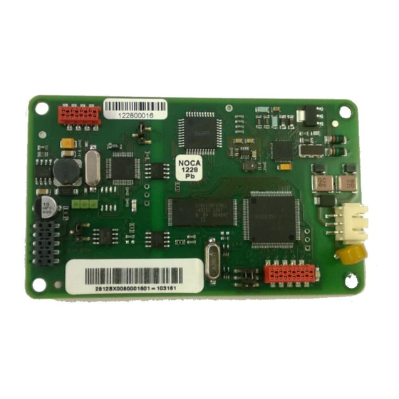
Page 21: Socket, Led And Jumper Functions Of The Ff Card
Fitting the FF CP card Socket, LED and Jumper functions of the FF card Bar code LED 1 SK 3 SK 1 LED 2 Bar code Fig 3.7: Network Interface Card - Jumper and LED functions. The FF CP card includes two connectors (SK1 and SK3), two LED indicators (LED1 and 2) and four jumpers, (JP1 –... - Page 22 Foundation Fieldbus CP Option Card Technical Manual JP1, Simulation In simulation mode, the user is permitted to write to primary input/output Mode Jumper actuator variables through the status and value attributes normally written to by the transducer block. With JP1 ‘On’ a function block may have its simulation ‘active’...
-
Page 23: Iec 61158 Data Highway And Connections
IEC 61158 Data Highway IEC 61158 DATA HIGHWAY AND CONNECTIONS Data highway The Foundation Fieldbus network is based on the IEC 61158 data highway using copper conductors. The network also carries the power used to supply each node on the network. In the case of the FF card, the FF interface is powered from the fieldbus network. -
Page 24: Fieldbus Power Supply
Foundation Fieldbus CP Option Card Technical Manual Fieldbus power supply The FF card takes power from the H1 data highway. This means the internal function blocks are available for control connection between devices even when the actuator has no power. The power is taken from a special DC power supply connected onto the network through a suitable filter. - Page 25 IEC 61158 Data Highway Example of voltage drop calculation: Assume the cable is Type A (24 Ohm per km per conductor), the resistance of each 1000 metre pair is 24 x 2 = 48 Ohms per km. The current drawn by each node A1 to A6 is 20 mA. Voltage drop Power supply to A1 = current x resistance = (6 x 0.020) x (0.8 x 48) = 4.6 volts...
-
Page 26: Termination Network
Foundation Fieldbus CP Option Card Technical Manual Termination network Each highway must be terminated correctly at the two ends of the data highway. The terminator comprises at least one resistor and capacitor in series and they provide a characteristic impedance of 100 Ohm at 39 kHz. -
Page 27: The Actuator Input And Output Signals
Actuator Input Output Signals THE ACTUATOR INPUT AND OUTPUT SIGNALS The FF CP card provides feedback data about its status and that of the actuator to the Foundation highway. This data is contained in the Transducer function block and is fully listed in the section on Function Blocks. -
Page 28: Controls
Foundation Fieldbus CP Option Card Technical Manual Controls The FF CP card can be used to control the actuator and position the valve. The valve may be moved fully closed, fully open or to an intermediate position. Additionally, the actuator can make the valve adopt an Emergency Shut Down position and in some actuators perform a partial stroke test. - Page 29 Actuator Input Output Signals The FF commands operate on the Transducer block through Digital Output (DO) blocks that are already connected in the default configuration. The network commands will operate the actuator provided:– • Local/Local Stop/Remote selector is in ‘Remote’ (or “Run” in a CVA). •...
- Page 30 Foundation Fieldbus CP Option Card Technical Manual Note: The following functions are not an option with all actuators – see Fig: 5.2. Partial Stroke The actuator will move the valve to an intermediate position and back to the start position provided it is at the correct end of travel position when the command is issued.
-
Page 31: Controls Priority
Actuator Input Output Signals 5.1.1 Controls priority Since there can be several potential sources for control inputs the actuator and FF CP card assigns a priority for those occasions when two or more commands are applied simultaneously. Local controls go direct to the main board and override any Foundation controls and any hard-wired controls except hard-wired ESD. -
Page 32: Foundation Control Using Do Blocks Only
Foundation Fieldbus CP Option Card Technical Manual 5.1.2 Foundation control using DO blocks only Discrete action control is achieved using the DO blocks in the FF CP card. Each DO block output has a value between 0 and 255. If the host DCS system uses its ‘Boolean Fan In’ function, most of the discrete controls can be achieved using one DO block –... -
Page 33: Foundation Control Using Both Do And Ao Blocks
Actuator Input Output Signals If the AO output is set to 0% and limited range positioning is not being used (selected via the Transducer block), the actuator will operate as though a ‘close’ command had been sent. Similarly, if the AO output is set to 100% under these conditions, the actuator will interpret the instruction as an ‘open’... -
Page 34: The 'S' Contacts (Rly 1 To Rly 4) Controlled By The Do Blocks
Foundation Fieldbus CP Option Card Technical Manual The ‘S’ contacts (RLY 1 to RLY 4) controlled by the DO blocks 5.1.5 Note: This option is not available on all actuator types, see fig 5.2. The actuator has four ‘S’ contact outputs that may be configured to report the status of the actuator with signals such as Open Limit, Closed Limit etc. -
Page 35: Discrete Input Status Feedback
Actuator Input Output Signals Discrete Input status feedback The FF CP card has DI (Discrete Input) function blocks that may be used to report the valve and actuator status over the network. The conventional contact indications are also available from the actuator limit switches and indication contacts. -
Page 36: Discrete Inputs
Foundation Fieldbus CP Option Card Technical Manual 5.2.1 Discrete Inputs Close Limit This data bit indicates that the actuator has reached the closed position. The limit switch should be set slightly within the actual valve stroke to allow for torque seating or overshoot on closing without damaging the valve. - Page 37 Actuator Input Output Signals General Alarm If any of the following conditions are true this bit will be true (1):– Thermostat tripped Monitor Relay Valve Obstructed Valve Jammed Manual Movement Valve Obstructed This bit will be true (1) if the actuator stops in mid-travel when not expected to do so after receiving a command to move.
- Page 38 Local Stop won’t cause a monitor Relay Alarm – see section 2.2 of PUB002-040: http://www.rotork.com/master-popup/8953/ The mains supply is always monitored and if one of the three phases is lost, this bit is set. If the actuator is operated from a single phase supply and this is lost, then communications with the actuator will also be lost.
- Page 39 Actuator Input Output Signals Valve Obstructed/Jammed This bit is a combination of the Valve Obstructed and the Valve Jammed bits. If either is true this bit will be true (1). Valve Moving by Hand The manual movement of the valve is reported as true (1) if the actuator is moved by the handwheel away from the last position.
-
Page 40: Discrete Inputs Reporting The Ff Cp Card Condition
Foundation Fieldbus CP Option Card Technical Manual Digital Input HW_DI-4 This bit reports the status of the contact connected to the actuator hard-wired ESD terminals. The input can be used to control the actuator or simply to report the status of a plant feedback signal. The function is set in the Auxiliary Input Mask parameter, which determines whether the bit is reported as true (1) for a closed contact or an open contact and whether the input controls the actuator or not. -
Page 41: Actuator Analogue Input Feedback
Actuator Input Output Signals Actuator Analogue Input feedback The FF CP card includes two Analogue Input blocks, AI 1 and AI 2, which are used to report information about the valve and actuator. These blocks are connected to the Transducer block in the default configuration. - Page 42 Foundation Fieldbus CP Option Card Technical Manual This page has been left intentionally blank 42 of 116 Publication PUB089-005-00_0618...
-
Page 43: Function Blocks
Actuator Input Output Signals FUNCTION BLOCKS Fig 6.1: Function blocks within the FF CP card Function blocks provide the heart of the Foundation Fieldbus system. Each device on a network includes at least one Transducer block and a Resource block to allow the equipment to be configured to operate on the network. -
Page 44: Resource Block
Special device status parameters None Indexes 1 to 3 contain information for ITK test and Rotork firmware version control. Indexes 4 to 9 give information on the current status of the various function blocks and the actuator control interface as shown below. - Page 45 Actuator Input Output Signals Index 5: DEVICE_STATUS2 Title Description No response from Actuator controller There is a communications failure between the Fieldbus and actuator Checksum error Checksum error on the FIC TB in OOS mode Transducer block is in OOS mode Index 6: DEVICE_STATUS3 Title Description...
- Page 46 Foundation Fieldbus CP Option Card Technical Manual Index 7: DEVICE_STATUS4 Title Description PID1 in OOS PID block is Out of Service PID1 Bypass PID1 has bypass active Index 8: DEVICE_STATUS5 This index is reserved for future use. Index 9: ACT_DEVICE_STATUS Title Occurs When Action Required...
-
Page 47: Transducer Block
Actuator Input Output Signals Transducer Block The Transducer Block is at the heart of the function block structure in the FIC. It contains all of the information with regards to setup and control of the actuator as well as its status feedback and provides the link between standard function blocks and the actuator mechanisms. - Page 48 TRANSDUCER_TYPE Identifies the transducer. XD_ERROR Error Codes None COLLECTION_DIRECTORY FF specific parameter None ACT_MAN_ID Manufacturer ID, i.e. Rotork 0xFF01 65281 Value / type: 0 – Unknown (default) 2 – A,AQ,Q, Integral 6 – IQ 8 – IQT 9 – EH 10 –...
- Page 49 Actuator Input Output Signals Index Parameter Description Range Default Units Class Valve Manufacturer’s SN VALVE_SN Null None VALVE_TYPE Valve Manufacturer’s SN Null None Value: 0- No Command 1- Stop command 2- Close command 4- Open command Final Fieldbus command to ACTUATOR_CONTROL 8- ESD command None...
- Page 50 Foundation Fieldbus CP Option Card Technical Manual Index Parameter Description Range Default Units Class FINAL_VALUE_CUTOFF_LO Cut-off levels for output LOCAL_FINAL_VALUE_AO Position Read back Value 0.0-100.0% FINAL_VALUE_DO1 DO Output Value Hexadecimal 0-0xFF None LOCAL_FINAL_VALUE_DO1 DO Read back Value Hexadecimal 0-0xFF None FINAL_VALUE_DO2 DO Output Value Hexadecimal 0-0xFF...
- Page 51 Actuator Input Output Signals Index Parameter Description Range Default Units Class Value: 0 – Positioning mode 1 – ESD 2 – S5 relay operate 3 – Partial stroke with Used for selecting DO4 Control mode None function DO control only 4 –...
- Page 52 Foundation Fieldbus CP Option Card Technical Manual Index Parameter Description Range Default Units Class Datalogger Data – latest 0 – 120% Torque at 40% - close direction value Datalogger Data – latest 0 – 120% Torque at 50% - close direction value Datalogger Data Datalogger 0 –...
-
Page 53: Changing The Settings In The Transducer Block
Actuator Input Output Signals 6.2.2 Changing the settings in the Transducer block. The functional operation of the actuator can be modified over the Foundation Fieldbus by editing the Transducer Block. Note that changes to some parameters can only be made when this block is in the ‘Out Of Service’... -
Page 54: Editing The Foundation Specific Parameters 1-23 And 99
Foundation Fieldbus CP Option Card Technical Manual 6.2.3 Editing the Foundation specific parameters 1-23 and 99 These parameters include settings that will be specific to the application and the method of control adopted for the network as a whole. Some are related to standard FF functions and are not described here. - Page 55 Actuator Input Output Signals Index 52 and 53 Deadband and Hysteresis When using position control by sending a value to the Actuator Position DV set-point, there are a number of parameters used to tune the position controller and reduce the possibility of damage to the actuator.
- Page 56 Index 56 to 58 This is a Rotork feature that is common for all our network products. The feature is used to enable the user to set a position to which the actuator is required to go or to take no action at all if the FF CP card loses communication with the network.
- Page 57 Actuator Input Output Signals Index 59 Auxiliary Mask (Function) This parameter relates to the IQ3/IQT3/SI /CK actuators only and allows the auxiliary inputs (Open, Stop, Close, ESD) to be set to control the actuator or simply report their status. In addition, it allows the sense of the input (open or closed contact) that is reported as true (1) to be set.
- Page 58 Foundation Fieldbus CP Option Card Technical Manual Example 1 The default value of '15' (0000,1111 binary or 0F hex) makes all 4 inputs report closed contacts as true (1) and none of the inputs will operate the actuator. Example 2 The value 255 (1111,1111 binary or FF hex) makes all 4 inputs report closed contacts as true (1) and all the inputs control the actuator in...
-
Page 59: Editing The Control Parameters 65 - 66
Actuator Input Output Signals 6.2.5 Editing the control parameters 65 - 66 Index 65 Control mode Most control schemes will be executed using the multiple bit function provided by a single DO block. DO 1 to DO 3 have a fixed set of 8 bits each that will suit most applications using discrete control. However, if analogue control alone is being used, or there are some special requirements for the control action, or single bit control is being used, DO 4 may need to be used in one of its mode settings. -
Page 60: Analogue Input Blocks
Foundation Fieldbus CP Option Card Technical Manual Analogue Input blocks The FF CP card includes two Analogue Input (AI) blocks. AI 1 Valve Current Position Output (analogue % value) The % ‘Open’ value (position) of the valve. The range is 0.0-100.0% and the end values relate to the close (0%) and open (100%) position limit switches. -
Page 61: Discrete Input Blocks
Actuator Input Output Signals Discrete Input blocks There are five Discrete Input Blocks (DI) included on the FF CP card. These DIs are preconfigured to read back information from actuator. The description of each reported data bit is included in section 5. OPTIONAL Transducer OUTPUT... - Page 62 Foundation Fieldbus CP Option Card Technical Manual Block Operation DI 2 Open limit Close limit Actuator opening Actuator closing (Selector not in “Run” on a CVA) Not in remote General alarm Valve obstructed Valve jammed Selector In remote (Selector in “Run” on a CVA) DI 3 Selector In Local Stop (Selector in “Stop”...
-
Page 63: Analogue Output Block
Actuator Input Output Signals Analogue Output block There is one Analogue Output (AO) block in the FF CP that is designed to allow the valve under control to be positioned to a specific value over its position range of 0.0-100.0%. ... - Page 64 Foundation Fieldbus CP Option Card Technical Manual Fig 6.8: Setting IO_OPTS to PV for BKCal_Out The AO block acts as a positioner for the valve and actuator. The positioning action is initiated by setting the DO function to Position Control Enable through the DO blocks, or by setting the Control Mode (Transducer block parameter 65) to AO only.
-
Page 65: Discrete Output Blocks
Actuator Input Output Signals Discrete Output blocks Discrete (Open/Stop/Close) control of the actuator, or mixed discrete and analogue position control is possible provided the FF CP card is set up correctly in the Transducer block and the correct settings are applied. There are 4 Discrete Output (DO) blocks in the FF card that allow the actuator to be moved. -
Page 66: Multiple Block - Single Bit Control
Foundation Fieldbus CP Option Card Technical Manual Multiple block – single bit control 6.6.1 Bit 0 = ‘Close’. DO 1 Bit 0 = ‘Open’. DO 2 Bit 0 = ‘Stop’. DO 3 Bit 0 = selected by mode – see below. DO 4 * Note: Mode... - Page 67 Actuator Input Output Signals Block Operation Read-back DO 3 Stop Actuator not moving Close Close limit Open Open limit Position control enable Position control enabled Set relay 1 relay 1 set Set relay 2 relay 2 set Set relay 3 relay 3 set Set relay 4 relay 4 set...
-
Page 68: Pid Control Block
Foundation Fieldbus CP Option Card Technical Manual Block Operation Read-back Position control enable DO 4 Position control enabled Mode 6: Partial stroking Partial stroking enabled Close Close limit Open Open limit Stop Actuator not moving Set relay 1 relay 1 set Set relay 2 relay 2 set Note: Ensure that parameters 65 (Control Mode) and 66 (Discrete Block Control) in the... -
Page 69: Control Selector Block
Actuator Input Output Signals Control Selector block The actuator includes a standard control selector block intended to select one of two or three control signals in a manner determined by SEL_TYPE. The inputs and outputs of this block are not directly linked to the actuator transducer block. - Page 70 Foundation Fieldbus CP Option Card Technical Manual This page has been left intentionally blank 70 of 116 Publication PUB089-005-00_0618...
-
Page 71: Link Active Scheduler (Las)
LAS on each FF H1 highway. All Rotork FF CP cards are supplied set to operate as a Basic device but can be configured to be LMs. When configured as LMs they are capable of assuming network control by switching automatically to become the LAS when the highway LAS goes offline. - Page 72 Foundation Fieldbus CP Option Card Technical Manual In order to change the FF01 CP card from a Basic unit to an LM a suitable configuration tool or dialogue tool must be used. If the NI FF configurator tool is used it’s simply a matter of a right mouse click on the device tag, select “Change device type”...
- Page 73 Setting Up The FF CP Card Fig 7.3: Management Information Base (MIB) showing BOOT_OPERAT_FUNCTIONAL_CLASS Once the LM type has been selected, the configuration tool can be used to download the system configuration. The schedule will reside in all the Link Masters and be executed by the one that is active, the Link Active Scheduler.
-
Page 74: Creating A Schedule
Foundation Fieldbus CP Option Card Technical Manual Creating a schedule In order to use any Function Block, with the exception of the Resource Block and the Transducer Block, the required blocks must be placed in a ‘Function Block Application’ using a suitable configuration tool. -
Page 75: Connecting The Blocks
Setting Up The FF CP Card Connecting the blocks The function blocks used to execute the control strategy must be connected. The interconnection of the blocks requires the use of a suitable Configuration tool. All the blocks in the FF CP card are already instantiated and ready for use. -
Page 76: Optimising The Downloaded Schedule
Foundation Fieldbus CP Option Card Technical Manual Optimising the downloaded schedule A downloaded schedule should consume no more than 50% of the highway’s macro-cycle time. Failure to adhere to this guideline may result in the FF card not functioning as expected. It might be possible to increase the macro-cycle period if the 50% threshold isn’t met with the DCS’s default macro-cycle time. -
Page 77: Setting Up The Ff Cp Card (Quick Start Guide)
These reside in the Transducer Block and can only be accessed via the FF highway. They can only be altered when the Transducer Block is in OOS mode. There are some actuator positioning parameters that can be checked / set using the Rotork setting tool. -
Page 78: Setting Up With The Setting Tool
Foundation Fieldbus CP Option Card Technical Manual Setting up with the Setting Tool The actuator includes a communication port for setting the actuator performance, limit switches etc. via the Setting Tool. This communication link can be used to set some, but not all, of the actuator specific Transducer Block parameters. -
Page 79: Insight 2
This software can be used to configure and view the settings and configuration of the Rotork actuator. It can be freely downloaded from the Rotork website. It designed to be run from a Windows computer and connects to the actuator using Bluetooth. Please see the relevant Rotork technical manual for more details. - Page 80 Foundation Fieldbus CP Option Card Technical Manual Other control parameters can be both viewed and modified. Ideally any changes should still be checked with an FF configuration tool to ensure optimum actuator and network compatibility. Figures 8.2 and 8.3, below, illustrate the access route through the actuator menu screens to reach the settings that affect the TB in the FF CP card.
-
Page 81: Methods
Setting Up The FF CP Card Methods The recommended way to set up the control and reporting function of the FF CP card is to use the Methods editor. The Methods tab on the Transducer block allows access to a sequence of questions that set up all the actuator control parameters as they are answered. -
Page 82: Control Output Function Block Settings
In order for a configuration tool such as those supplied by SMAR, NI and Yokogawa to parameterise the Actuator Fieldbus Card, the correct Device Definition files need to be loaded in to the configuration environment. These files are freely available for download from www.rotork.com The Foundation Fieldbus control of the actuator can be: ... -
Page 83: Analogue Only Control
Setting Up The FF CP Card 8.4.1 Analogue Only control Uses AO block only – no discrete control permitted. Transducer Block Settings Param. 52 – Deadband Set between 0-25.5% (typically 5%) Param. 53 – Hysteresis Set between 0-25.5% (typically 2%) Param. -
Page 84: Mixed Analogue And Discrete Control
Foundation Fieldbus CP Option Card Technical Manual 8.4.3 Mixed Analogue and Discrete control Uses the AO block and one or more DO blocks. Multiple Bit Support Systems using the multiple state of a single DO block, with only one DO block selected for use. (Unused DO blocks must be left OOS). -
Page 85: Status Feedback Function Block Settings
Setting Up The FF CP Card Status feedback function block settings The current status of actuator position, active control functions and fieldbus availability are reported in several parameters of the transducer block and through the Discrete Input and Analogue Input blocks. The only settings that need be considered are those for limited range positioning. -
Page 86: Default Settings
Foundation Fieldbus CP Option Card Technical Manual Default settings Transducer Block Param. No. Description Range Default Setting Limited Range 0-100% Position Minimum Limited Range 0-100% 100% Position Maximum Deadband 0.0-25.5% 5.0% Hysteresis 0.0-25.5% 2.0% Slow Mode Range 0-100% Motion Inhibit Time 0-255s 5 sec Action on Loss of... -
Page 87: Using The Dtm (With Fdt)
Using the DTM (with FDT) Rotork’s DTM is downloadable via http://www.rotork.com/document/index/versions/masterID/55353/ Rotork does not supply a Comm DTM nor does it supply an FDT. These must be purchased from another vendor. This approach enables the major TB parameters to be configured. - Page 88 Foundation Fieldbus CP Option Card Technical Manual Fig 8.6: Setting the actuator positioning parameters Fig 8.7: Setting the FF control parameters 88 of 116 Publication PUB089-005-00_0618...
-
Page 89: The Ff Cp Card Firmware And Dd Files
Foundation. The Rotork web site is regularly maintained and always contains the latest version of the DD files for the module. These may be newer than those posted by the Foundation on their web site. We recommend downloading the latest version from our web site at www.rotork.com. - Page 90 Foundation Fieldbus CP Option Card Technical Manual This page has been left intentionally blank 90 of 116 Publication PUB089-005-00_0618...
-
Page 91: Appendix A - Handling Fault Conditions
Appendix APPENDIX A – HANDLING FAULT CONDITIONS. Foundation Fieldbus blocks have a large number of parameters which influence the way in which the actuator responds to commands from the Fieldbus. In the event that communications are lost to the actuator, a number of these parameters are available to allow a predictable and deterministic reaction. The example below shows how an action may be configured to determine how a Digital Output Block will react on the loss of the cascade input to the block. -
Page 92: Appendix B - Function Block Mode - Lo
Foundation Fieldbus CP Option Card Technical Manual APPENDIX B – FUNCTION BLOCK MODE – LO The status of each of the Function blocks can be read by the Host system. Each block has a minimum of three states taken from the list below: Out Of Service AUTO Automatic... -
Page 93: Appendix C - Pid Application
Appendix APPENDIX C – PID APPLICATION In this example, a flow transmitter FT provides a measurement (PV) which is required to position an actuator M (OUT) Diagram of the PID Function to maintain the required process flow Block showing the relationship of the with respect to a set point (SP). - Page 94 Foundation Fieldbus CP Option Card Technical Manual The function block application which might be configured for this application is shown below. In this case the National instruments configurator has been used. Fig C.2: Setting the FF control parameters This dialogue box is used to adjust the scaling of the parameters supplied to, or derived through, the processing of the control loop.
- Page 95 Appendix Familiar tuning constants can be seen in this dialogue block together with others specific to this implementation of a PID block. For full information on the operation, configuration and tuning of PID loops, all the relevant loop component manufacturer’s information should be referred to.
-
Page 96: Appendix D - Itk6 Ff Specification Datasheet
Foundation Fieldbus CP Option Card Technical Manual APPENDIX D – ITK6 FF SPECIFICATION DATASHEET D.1 Basic Fieldbus Function Blocks Function block Quantity Execution Time (ms) Transducer Block (TB) Resource Block (RB) Analogue Input (AI) Digital Input (DI) PID, PI, I Controller (PID) Analog Output (AO) Discrete Output (DO) Control Selector (CS) -
Page 97: D.3 Segment Information
Appendix D.3 Segment Information 00FF010003:Rotork-Ver3:YYWWSSSSS YY-year WW-week number Device ID SSSSS - unique serial number Baud Rate 31.25K Device Address LAS capable Quiescent current draw (mA) Communicating current draw (mA) Power up current draw (mA), includes inrush Upgrade power draw (mA) -
Page 98: Appendix E - Namur Ne 107 - Guidelines For Setting Up
The broadcast alarms require priority FD_.._PRI to be enabled. The Rotork device has a number of alarms that can be selected for each diagnostic level, these are selected in the MAP and you can see which ones are then active in the ACTIVE parameter. - Page 99 Appendix The picture below shows how the selectable items are displayed on the NI configurator tool – all the following screen shots are from the NI configurator: Fig E.2: The Namur 107 list of items to be monitored Publication PUB089-005-00_0618 99 of 116...
- Page 100 Foundation Fieldbus CP Option Card Technical Manual The ITK6 fieldbus device Resource block default Diagnostics settings are as follows: Fig E.3: The RB’s Namur 107 settings 100 of 116 Publication PUB089-005-00_0618...
-
Page 101: Test Set Up For Fd
Appendix Test set up for FD_.._ACTIVE: The easiest alarm to raise is the ‘unavailable for Remote Control’ alarm. This will be active if the actuator control knob is set to Local or Local Stop. The picture below shows the control knob in the remote position which will show no alarm: Fig E.4: The front of an IQ3/IQT3 showing actuator control knobs... - Page 102 Foundation Fieldbus CP Option Card Technical Manual Fig E.6: Checking the Namur “FD_FAIL_MAP status 102 of 116 Publication PUB089-005-00_0618...
- Page 103 Appendix When the control knob is set to local or local stop the actuator will be unavailable for remote control. Local Stop: Local Control: The following will be shown for FD_FAIL_ACTIVE: Fig E.7: Checking the Namur active alarm status in the RB. Setting the control knob back to the remote position will remove the active alarm.
-
Page 104: Test Set Up For Fd
Foundation Fieldbus CP Option Card Technical Manual Test set up for FD_.._ALM: To enable the broadcast alarms (FD_FAIL_ALM) the FD_FAIL_PRI will need to be set up with a priority level. The setting is made as shown: Fig E.8: Setting the priority level. Once this setting is made the alarm is able to be broadcast and the following is shown in the FD_FAIL_ALM parameter: Fig E.9: Alarm state reported. - Page 105 Appendix If there is a need to mask out an alarm and stop it from generating a broadcast alarm the FD_.._MASK setting is required to be set up: Fig E.11: Setting the mask. Setting the bit above will prevent the alarms from being broadcast, but will not stop the alarm from being available to poll (ACTIVE).
-
Page 106: Appendix F - Changing The Itk Revision
Once the correct password has been entered, a different ITK version can be selected and entered. Once done, it is necessary to restart the Rotork Foundation Fieldbus card to enable the setting to take effect. This can be done by cycling the power on the fieldbus network or disconnecting the fieldbus connection to the Rotork Foundation Fieldbus card. - Page 107 The FF card’s software version to be at least V/M3.1B1.4H1.1. The FF highway to be both connected and powered up. The actuator’s mains power to be applied. The NI configurator tool to be running and have all versions of Rotork’s ITK DD files, downloadable via: http://www.rotork.com/en/product/index/foundationfieldbusliterature In order to see what the current ITK version is, select the Resource Block and click on the “Others”...
- Page 108 Foundation Fieldbus CP Option Card Technical Manual Then click on the “Diagnostics” tab and highlight “VALUE_5” in the “TEST_RW” area To change the ITK rev enter the value 0x46, 0x51 or 0x61 and click on “Write Changes” Fig F.3: Access the RB, diagnostics tab For this value to be taken by the FF card it will needs to be reset.
- Page 109 Appendix Restarting the processor doesn’t delete the tag names nor any project schedule that the card may have. When the card re-starts it will create a new FF entry in the NI Configurator tool’s list of devices. Delete the old entry by right-clicking on the original actuator tag (now marked by an error symbol, as shown on the right) and selecting “Delete”.
-
Page 110: Appendix G - Dtm
This link also contains the DTM user manual PUB089-004. Note: Rotork does not supply a Comm DTM nor does it supply an FDT. These must be purchased from another vendor. The DTM provides read / write access to the key Transducer Block parameters and can be used with Rotork’s ITK4.6, 5.1 and 6.1 FF cards.. - Page 111 Appendix Fig G.2: Setting the control mode and discrete block control Fig G.3: Setting the actuator positioning parameters Publication PUB089-005-00_0618 111 of 116...
- Page 112 Foundation Fieldbus CP Option Card Technical Manual Fig G.4: Setting the FF card’s operational parameters 112 of 116 Publication PUB089-005-00_0618...
-
Page 113: Appendix H - Host Interoperability Support Test (Hist)
It is not a service that Rotork can offer. Rotork has deposited FF actuators at all the major DCS vendors test labs to enable them to test our cards when required. For specific projects, Rotork can provide a list of HIST approvals. -
Page 114: Appendix I - Common Problems
Setting the FF card’s address beyond the usable address range configured in the DCS. The factory default setting for FF cards supplied inside a Rotork actuator is 34. If the DCS’s useable address range is set to 33 or lower the actuator will not be detected by the DCS. FF cards supplied as spares will be despatched with an un-configured address. - Page 115 Appendix Output Blocks Setting the “Discrete Block Control” mode in the Transducer Block to multiple support and downloading more than one DO in the schedule. Whilst all five DI blocks can be used in multiple support mode to give 40 DI states, only one DO can be used.
- Page 116 675 Mile Crossing Blvd http://www.rotork.com England Rochester BA1 3JQ New York 14624 Rotork reserves the right to amend and Tel: +44 (0) 1225 733 200 change specifications without prior Fax: +44 (0) 1225 333 467 Tel: +1 585 247 2304 notice.
Need help?
Do you have a question about the Mk3 and is the answer not in the manual?
Questions and answers
How to check stall at MOV IQMK3