
Related Manuals for rotork Modbus


Summary of Contents for rotork Modbus
- Page 1 Modbus RTU Actuator Control Mk 3 Option Card Technical Manual (IQ3, SI , CVA, CMA, K-Range) Publication PUB091-004-00_0918...
- Page 2 Note 4: Throughout this manual the Modbus Module may simply be referred to as the module, card or MFU (Modbus Field Unit – the circuit board fitted to the actuator in the field). Note 5: Inputs are the status messages from the actuator and outputs are the command messages to the actuator.
-
Page 3: Table Of Contents
Operation and Storage ......................10 Fitting the Modbus module Option Card ..........11 Inside an IQ3 actuator ......................11 Replacing or Fitting a Modbus Module Option Card ............11 Inside an SI₃ actuator ......................12 Inside a CVA actuator ......................13 Inside a CMA actuator ...................... - Page 4 7.9.8 Analogue Input Max/Min (Register 20) ................58 7.9.9 Comms Fault Timer (Register 21) ................... 58 7.10 Modbus Network Related Configurable Parameter Registers ........59 7.10.1 Modbus Address (Register 22) ..................59 7.10.2 Baud Rate (Register 23) ....................59 7.10.3 Parity and Stop Bits (Register 24) ...................
-
Page 5: Glossary Of Terms
Master/Slave Method of communication used by the Modbus Module. The fieldbus requires a Modbus master to control the data exchange on the highway. Modbus The communication protocol used for data exchange, as defined in IEC 61850. -
Page 6: Abbreviations
Modbus MFU Option Card Installation Manual Partial Stroke Test Moving a little-used valve by a small percentage from an end limit and then returning it, proving that it will operate when required. Safety related. RS-485 The electrical properties of the data highway as defined by the IEC 8482 standard, copper conductors, 2-wire twisted pair. -
Page 7: Introduction
Field connections. All adjustments to the settings for the module may be made via the Modbus data highway using a Modbus master tool or via the Infra-red or Bluetooth actuator setting tools for those products that support those interfaces. -
Page 8: General
Modbus MFU Option Card Installation Manual 1.1 General The Modbus Module has three variants: Single RS-485 highway Dual Independent isolated RS-485 highways Single RS-485 highway with inbuilt isolating repeater Communication Medium RS-485 2-wire highway (single or dual), half duplex... -
Page 9: Modbus Option Card Properties
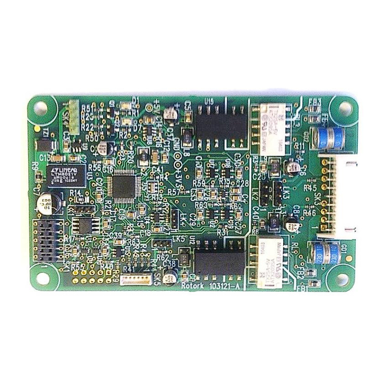
Modbus RTU network and the communication protocol used within the actuator. There is no intermediate circuit board that it plugs into. We refer to it as the Modbus Field Unit, MFU. The MFU is a single rectangular printed circuit board that fits inside the actuator electrical housing. It connects directly to the Control Module PCB of the actuator by a ten pin connector (10 way header, SK2). -
Page 10: Electrical Properties
Additionally, the circuit includes non-volatile memory that is used to store specific field unit communications settings. The Modbus RS-485 fieldbus data highway connections are fully isolated from the actuator electronics. 2.3 Operation and Storage The MFU is designed to be stored in the actuator and operated within the same environment as the actuator. -
Page 11: Fitting The Modbus Module Option Card
The MFU is connected to the control module by a 10 way header (SK2). The wiring harness from the actuator terminal bung connects the Modbus RS-485 field connections to SK3. 3.2 Replacing or Fitting a Modbus Module Option Card The MFU should be replaced or fitted only in a suitable environment. -
Page 12: Inside An Si₃ Actuator
Once power is applied, the field unit parameters should be checked and corrected, where necessary. Modbus parameters can be set and adjusted either by using the Infra-red and Bluetooth setting tools or by Insight 2 using Bluetooth. The parameter setting procedure is covered by the IQ3 Full configuration, status and monitoring user manual, PUB002-040, available on the Rotork web site, www.rotork.com... -
Page 13: Inside A Cva Actuator
The MFU in the CVA must be enabled. This would usually be done during factory test, but may be required to be completed on site for conversions to Modbus or if a replacement card is fitted. To enable the card, the Rotork PDA software Enlight (downloadable from the Rotork web site) is required to be used to change parameter 34. -
Page 14: Inside A Cma Actuator
10-way header, which is SK2 on the MFU board. There is a wiring loom which brings the RS-485 network connection to SK3 on the MFU. This loom comes from SK5 and SK6 of the Modbus terminal board, which in turn is where the field network connections are made. -
Page 15: Fig 6: Cma Menu Structure For Setting Up The Actuator: Start At The Basic Setting
Modbus Option Card Properties Fig 6: CMA menu structure for setting up the actuator: start at the BASIC setting and select the ADVANC button. Publication PUB091-004-00_0918 15 of 64... -
Page 16: Fig 7: Cma Menu Structure For Setting Up The Actuator: From The Advanc Setting
Modbus MFU Option Card Installation Manual Fig 7: CMA menu structure for setting up the actuator: from the ADVANC setting, select the COMMS button. 16 of 64 Publication PUB091-004-00_0918... -
Page 17: Fig 8: Cma Menu Structure For Setting Up The Actuator: From The Comms Setting
Modbus Option Card Properties Fig 8: CMA menu structure for setting up the actuator: from the COMMS setting, select the Modbus button. From here, you can adjust the individual Modbus settings. Fig 9: Connections to the MFU located in a CMA actuator... -
Page 18: Inside A K-Range Actuator
SK2 on the MFU card plugs directly onto SK9 on the Main card, while a terminal bung loom brings the network Modbus signals to SK3 (shown on right hand side of photograph) on the MFU card. Modbus Option Card... -
Page 19: Rs-485 Data Highway, Connections And Mfu Setup
The length of the highway and number of devices connected will vary from project to project. The Modbus standard permits up to 32 devices to be connected per segment, though one of these devices will be the PLC. If more devices are needed, (up to the maximum addressable of 247) then RS-485 repeaters may be added after each group of 32. -
Page 20: Highway Topology
Modbus MFU Option Card Installation Manual With RS-485 the data passes over a single 2-wire cable, but the Modbus protocol is such that there are periods between messages when no devices are actively driving the lines. In order to ensure that data continues to flow correctly after these periods, it is advisable to ensure the lines are biased to suitable voltage levels during the time the line is idle. -
Page 21: Cable Types
The network must be connected using a suitable cable. Two conductors plus a shield and drain wire are required as a minimum, though Rotork recommends the use of a 3 wire cable to ensure the common mode voltage between all the actuators and the PLC is kept within the RS-485 specified limits. -
Page 22: Termination Network
The MFU has an internal termination resistor which does not require any external wiring to be included (unlike the previous version of Modbus field unit). The termination resistor, or resistors for a dual channel, can be electronically switched on through the setting menu within the IQ3. -
Page 23: Inter-Connecting The Highway And Setting Up The Mfu
Each data line A is positive with respect to data line B when the MFU is transmitting a ‘1’. The dual channel MFU uses a separate Modbus address for each channel, so it is possible to use the same address or different address on each channel. It is possible to communicate with both channels at the same time. -
Page 24: Single Highway With Internal Repeater
Modbus Module. The reply will appear, only, on the channel side where the message came in, i.e. a message received on channel 1 will be repeated over to channel 2 and once the message is processed the reply will appear only at channel 1. -
Page 25: The Actuator Input And Output Signals
The MFU allows the actuator to be controlled by, and to report data to, a suitable host device using Modbus RTU protocol. This section explains the data signals that are available for exchange and their meaning in relation to the actuator functionality. The data locations used for the Modbus registers and coils are given later in this manual. - Page 26 Note: – Requires Digital Input / Output card or Extra Relay card to be fitted – Requires a DSM or MSM with the optional potentiometer. The Modbus network commands for Open, Close and Stop will operate the actuator provided:- •...
- Page 27 ‘0’. Analogue Position Demand The source of this function is only over the Modbus RS-485 network. (Where multiple network cards or Folomatic is fitted, then this could be another source of positioning control). To initiate...
- Page 28 The hard wired Stop input acts as a change of state input. If the actuator is moving, opening the Stop input will stop the actuator. If the Stop input is already open and a Modbus command is sent to the actuator, the Modbus command will be initiated. To stop the actuator the hard wired input must be closed and opened again.
-
Page 29: Controls Priority
5.1.1 Controls Priority Since there are three potential sources for control inputs, the actuator and Modbus Module assign a priority for those occasions when two or more commands are applied simultaneously. In addition, the remote control hard wired inputs can be used as discrete input signals, to report the status of other devices or as control inputs. -
Page 30: Modbus Control Using The Actcon Register
✓ 5.1.4 Modbus Control using the Actuator Position DV register The analogue position control function will take priority over an earlier coil or ACTCON register command to open, stop, close, ESD or partial stroke test the actuator when a value is written to the Actuator Position DV register. -
Page 31: Iq3 Modbus Network Control Disable Feature
It is possible to set the IQ3 ESD/DI-4 input so that the actuator ignores open, stop, close, ESD, partial stroke test and position control signals sent over the Modbus network. If the ESD DI-4 / Net Disable parameter is set to Active, then when the ESD input connection is made (i.e. 24 volts applied to ESD), Modbus control is not allowed. -
Page 32: Digital Inputs From The Actuator
Remote Selected This bit is true (1) when the actuator three position Remote/Local Stop/Local selector is in the Remote position. The selector must be in this position for Modbus control of the actuator to be permitted. Local Stop The actuator three position selector passes from Local to Remote or Remote to Local through the Local Stop position. - Page 33 Input and Output Signals thermostat. The bit will remain set at logic 1 until the motor cools down and the thermostat resets itself. Monitor Relay This signal is true (1) when actuator remote control is not available. The actuator Monitor Relay status is a composite signal for several alarms.
- Page 34 Modbus MFU Option Card Installation Manual Moving Inhibited This bit will be true (1) when the Motion Inhibit Timer is active or the Interrupter Timer is active, or both are active. The Motion Inhibit Timer is used in position control to prevent the actuator from exceeding its prescribed number of starts per hour, or to reduce the effects of hunting during closed-loop control.
- Page 35 Input and Output Signals Digital Input DI-2 This bit reports the status of the contact connected to the actuator hard wired Close terminals. The input can be used to control the actuator or simply to report the status of a plant feedback signal. The function is set in the Auxiliary Input Mask parameter which determines whether the bit is reported as true (1) for a closed contact or an open contact and whether the input controls the actuator or not.
-
Page 36: Actuator Analogue Input Feedback
5.4 IQ3 Data Logger Information The Modbus Module also makes available some of the data logged information from registers in the database. The data available is updated when the actuator reaches the end of travel and stops moving, provided the actuator selector is in the ‘Remote’... - Page 37 Input and Output Signals Torque at x% when opening There is a set of registers that each record the last value for the torque generated when the actuator is moving from closed to open and reaches a particular position (x%). The registers contain 11 values of torque generated in 10% position increments between 0% and 100% of valve travel.
- Page 38 Modbus MFU Option Card Installation Manual The rest of this page is intentionally blank. 38 of 64 Publication PUB091-004-00_0918...
-
Page 39: Modbus Communication
1.750 1.750 1.750 )(ms) Note ①– In the Single Highway with Internal Repeater Modbus Module option there is a propagation delay in the repeater. Maximum period between request and response: 190 ms 6.3 Repeaters A single segment supports up to 32 nodes, one of which is usually the PLC. The addition of repeaters allows the segment to be extended in length or to increase the number of nodes connected to the network, or both. -
Page 40: Dual Channel Mode
6.4 Dual Channel Mode The dual channel version of the Modbus Module has two ports and allows two data highways to be used for communication from the host system to the module. These highways operate independently with a limit of 32 devices per segment and the ports on the module communicate with their associated highway. -
Page 41: Modbus Database
The data in the Modbus Module may be collected using a number of different Modbus function codes. Similarly the commands to the MFU can be either register or discrete based. This inbuilt flexibility is designed to allow for any host device to be able to access the actuator over a Modbus network in the simplest way. -
Page 42: Function Code Support
Modbus MFU Option Card Installation Manual 7.3 Function Code Support Details of the Request and Reply formats for messages can be found in the Modbus Application Protocol Specification V1.1b3, found at http://www.modbus.org. The following table lists the function codes supported by the Modbus Module. - Page 43 Code 08 - Loopback Diagnostic Test The purpose of the Loopback Test is to test the communication system between the Modbus Module and the host. This code can be regularly sent and used as a heartbeat to test the communications link.
-
Page 44: Broadcast Commands
The locations given in the database are those which should appear in the messages as they are transmitted on the Modbus link. Some host systems offset the addresses so far as the user is concerned. In such cases, the address programmed into the host would be different to those listed. All data locations listed start from 0. -
Page 45: Data Accessed With Function Code 02 - Read Discrete Inputs
Input and Output Signals DO-2 output coil status (extra relay S6) ① 0 - 1 DO-3 output coil status (extra relay S7) ① 0 - 1 DO-4 output coil status (extra relay S8) ① 0 - 1 Partial Stroke test 0 - 1 DO-5 output coil status (extra relay S9) ②... -
Page 46: Data Accessed With Function Code 03 - Read Holding Registers
Modbus MFU Option Card Installation Manual 7.6.3 Data Accessed with Function Code 03 - Read Holding Registers The accessible registers that can be read with this function code also include the Input registers. Location Data Range (Reg/Bit) Actuator moving 0 - 1... - Page 47 Input and Output Signals Location Data Range (Reg/Bit) 0 - 4 0 = stop 1 = close Actuator Digital Control 2 = open 3 = ESD 4 = partial stroke test 0 - 3E8 hex Actuator Position DV (desired value) (0.0 - 100.0%) Actuator Parameters see Section 8 12 bytes...
-
Page 48: Data Accessed With Function Code 04 - Read Input Registers
Modbus MFU Option Card Installation Manual Location Data Range (Reg/Bit) Close Motor Starts high order 0-FFFF hex Open Motor Starts low order 0-FFFF hex Open Motor Starts high order 0-FFFF hex Note: For CVA, Registers 56 & 57 give contactor counts for open and close directions. Register 58 is total distance travelled for CVA. -
Page 49: Data Accessed With Function Code 05 And 15 - Force Single And Multiple Coils
Input and Output Signals Data Accessed with Function Code 05 and 15 – Force Single and Multiple Coils 7.6.5 Location Data Range (Bit) Stop command output coil status 0-FF00 hex Close command output coil status 0-FF00 hex Open command output coil status 0-FF00 hex ESD command output coil status 0-FF00 hex... -
Page 50: Data Accessed With Function Code 08 - Loopback Diagnostic Test
Modbus MFU Option Card Installation Manual Location Data Range (Bit) ESD coil status Open coil status Close coil status Stop coil status Closed position limit Open position limit Monitor relay Reserved Data Accessed with Function Code 08 – Loopback Diagnostic Test 7.6.8... -
Page 51: Database Summary
Input and Output Signals 7.7 Database Summary: Publication PUB091-004-00_0918 51 of 64... - Page 52 Modbus MFU Option Card Installation Manual 52 of 64 Publication PUB091-004-00_0918...
-
Page 53: Configuration Registers
All the parameter registers have factory default settings designed to meet the most common requirements for the actuator. If these are not suitable for a particular application, then the values can be changed by using a Modbus communication tool. -
Page 54: Actuator Related Configurable Parameter Registers
000A hex - Setting the deadband lower than the hysteresis or the hysteresis greater than the Note: deadband causes the hysteresis to be set to 0.1% Modbus Network Related Network Configurable Parameter Registers Location Default Description Value/Range R/W Access... -
Page 55: Action On Loss Of Comms (Register 7)
Input and Output Signals 7.9.1 Action on Loss of Comms (Register 7) This register is used with register 13 (Comms Lost Position) and 21 (Comms Fault Timer). The Action on Loss of Comms register defines the actuator action that will result after the time set for the Comms Fault Timer (register 21) if there is no network communication activity detected by the MFU. -
Page 56: Fig 19: Deadband And Hysteresis Settings
Modbus MFU Option Card Installation Manual inertia of the valve. They will require adjustment for each specific application. In addition, the Motion Inhibit Timer is used to ensure the actuator does not carry out an excessive number of starts in a given period. -
Page 57: Motion Inhibit Timer (Mit) (Register 11)
Input and Output Signals 7.9.4 Motion Inhibit Timer (MIT) (Register 11) The MIT setting is the period that must elapse between consecutive starts of the actuator motor when in positioning mode. The time runs from when the motor stops until the next time it starts The idle period will prevent the actuator motor from exceeding its rated number of starts per hour. -
Page 58: Comms Lost Position (Register 13)
Analogue Input Max/Min (Register 20) This parameter register is used when the IQ3 actuator has a Modbus card and an Analogue Input card fitted. To calibrate the Analogue card, its maximum input is applied and a value of 1 is written to parameter 20. -
Page 59: Modbus Network Related Configurable Parameter Registers
7.10.1 Modbus Address (Register 22) The Modbus Address is the address on the network that the Modbus Module will respond to. The address can be in the range 1 to 247, though 247 is generally not used as this is the default address and may be used by any newly introduced device on the network. - Page 60 Modbus MFU Option Card Installation Manual The rest of this page is intentionally blank. 60 of 64 Publication PUB091-004-00_0918...
-
Page 61: Setting Up And Maintaining The Mfu
SETTING UP AND MAINTAINING THE MFU In most applications the majority of the default settings in the Modbus Module will be suitable for the operation of the valve and need not be altered. However, in every case it will be necessary to alter the address since the default should never be used within a live system (the default value is 247). -
Page 62: Maintenance And Repair
The table lists all the registers that must be checked and set up for each Modbus Module on a network. The data should be recorded for each module. -
Page 63: Troubleshooting
Input and Output Signals 8.5 Troubleshooting In general, most of the problems that are seen with actuators fitted to a Modbus network are due to wiring errors and are simple to test and fix. Often, the problem is that the network is connected to the wrong actuator terminals. The correct terminal numbers are given in the wiring diagram that comes with each new actuator. - Page 64 Modbus MFU Option Card Installation Manual http://www.rotork.com Rotork reserves the right to Rotork PLC Rotork Controls Inc. amend and change specifications without prior Tel: +44 (0) 1225 733 200 Tel: +1 (585) 247 2304 notice. Fax: +44 (0) 1225 333 467 Fax: +1 (585) 247 2308 e-mail: mail@rotork.com...
Need help?
Do you have a question about the Modbus and is the answer not in the manual?
Questions and answers