Advertisement
Quick Links
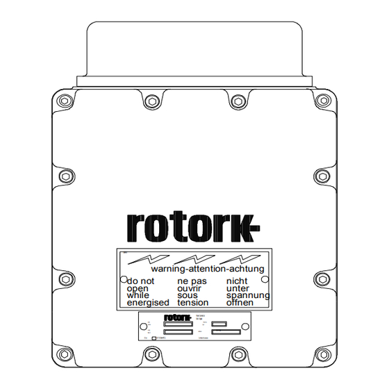
Pakscan General Purpose Field Control Unit
Publication - PUB059-021-00_0715
Technical Manual
rotork
Field control unit
COMMS IN
I/O
COMMS OUT
TAG
SUPPLY
Z24539-02
warning-attention-achtung
do not
ne pas
nicht
open
ouvrir
unter
while
sous
spannung
energised
tension
offnen
Rotork Control s Ltd.
Bath. Engl a nd
seri a l
P ak-B ox
number
t ype
w i r i n g
FLP/IP68/
encl o sure
di a g. no.
E E xd
IIB T 4 (Tamb=+70 C)
C erti f i c ate N o.xxxxxxxx
Advertisement

Related Manuals for rotork Pakscan GPFCU


Summary of Contents for rotork Pakscan GPFCU
- Page 1 Rotork Control s Ltd. Bath. Engl a nd seri a l P ak-B ox number t ype w i r i n g FLP/IP68/ encl o sure di a g. no.
- Page 2 As we are continually developing our products their design is subject to change without notice. © The contents of this document are copyright and must not be reproduced without the written per- mission of Rotork Controls Ltd. G.P.F.C.U. Technical Manual - Publication: PUB059-021-00_0715 2 of 52...
- Page 3 Contents Contents: Introduction Field Unit Properties Mechanical Properties Electrical Properties Operation and Storage Compatibility Paktester 2-wire loop Fitting the Field Unit Replacing or Fitting a Field Unit 2-wire loop Connections 2-wire loop interface Loopback Feature Loop By-pass Circuit Input and Output Signals Summary of Digital and Alarm Status Data Bits Digital Status Data Bits Alarm Status Data Bits...
- Page 4 Pakscan General Purpose Field Control Unit Technical Manual List of diagrams Figure page 7 The General Purpose Field Unit page 11 Pakbox PB2 mounted Field unit page 12 Rack mounted Field Unit page 12 Panel mounted Field Unit Page 15 Pakbox PB2 GPFCU to 2-wire loop connections Page 15 Panel mounted GPFCU to 2-wire loop connections...
- Page 5 Rotork actuator built since 1970, (for actuators built before this date refer to Rotork). It can also be mounted in a weatherproof box, or on a panel, or in a rack located in a control room and hard wired to the actuator. When programmed for general purpose control the field unit can be housed in either a PB2 Pakbox or it can be rack mounted.
- Page 6 Pakscan General Purpose Field Control Unit Technical Manual This page has been deliberately left blank G.P.F.C.U. Technical Manual - Publication: PUB059-021-00_0715 6 of 52...
- Page 7 Each terminal being clearly labelled with its function. 2.2 Electrical Properties Fig 1: The General Purpose Field Unit 1022-486 ISSUE 1.3 rotork The field unit processor is controlled by a programme stored in EPROM. The EPROM is located on the field unit board and marked as shown in figure 1.
- Page 8 Pakscan General Purpose Field Control Unit Technical Manual 2.3 Operation and Storage The field unit is designed to be stored and operated within the following constraints: Operating temperature: -30 C to +70 Storage temperature: C to +85 Relative Humidity: 5% to 95% (<50 C) non-condensing Vibration: 0.75g (0.5 Hz to 300 Hz)
- Page 9 Compatibility COMPATIBILITY The GPFCU is compatible with all Pakscan master stations built since 1990. Only one EPROM, (5152-410), is needed for both GP mode and actuator mode operation. The GPFCU cannot be used with a Pakscan I master station. 3.1 Paktester In order to be able to use a Paktester to set up and commission Pakscan field units, a Paktester fitted with software 5161-013 with a version higher than V5.0 must be used.
- Page 10 Pakscan General Purpose Field Control Unit Technical Manual This page has been deliberately left blank G.P.F.C.U. Technical Manual - Publication: PUB059-021-00_0715 10 of 52...
- Page 11 Fitting The Field Unit FITTING THE FIELD UNIT The field units will be factory fitted into their enclosures or supplied as stand alone or included in a 19” rack, if rack mounted GPFCUs are need Figure 2 below shows a sectional drawing of the Pakbox PB2, with the GPFCU located on the top of the box.
- Page 12 Pakscan General Purpose Field Control Unit Technical Manual If the device is a rack mounted field unit it will be supplied either as a stand alone unit or pre- mounted into the rack, as shown in figure 3. rotork Field control unit COMMS IN...
- Page 13 Fitting The Field Unit 4.1 Replacing or Fitting a Field Unit The field unit should be replaced or fitted only in a suitable environment. If field mounted, the actuator / Pakbox must be made electrically safe before opening any covers. On the PB2 the top cover should be removed and the plate with field unit unbolted from the cover.
- Page 14 Pakscan General Purpose Field Control Unit Technical Manual This page has been deliberately left blank G.P.F.C.U. Technical Manual - Publication: PUB059-021-00_0715 14 of 52...
- Page 15 2-Wire Loop Connections 2-WIRE LOOP CONNECTIONS The field unit should be wired in the communication loop as indicated in figures 5, 6 and 7. It is important to connect the current loop input terminal to the previous field unit’s current loop output terminal and the current loop output terminal to the next field unit’s current loop input terminal.
- Page 16 Pakscan General Purpose Field Control Unit Technical Manual This page has been deliberately left blank G.P.F.C.U. Technical Manual - Publication: PUB059-021-00_0715 16 of 52...
- Page 17 2-Wire Loop Interface 2-WIRE LOOP INTERFACE The field unit interfaces directly with the 2 wire loop. The circuits for the interface are isolated electrically from the actuator processors and field unit processor by opto-isolators. The interface includes protection devices to suppress the effects of lightning strikes or other high induced voltages.
- Page 18 Pakscan General Purpose Field Control Unit Technical Manual This page has been deliberately left blank G.P.F.C.U. Technical Manual - Publication: PUB059-021-00_0715 18 of 52...
- Page 19 Fig 8: Input and Output Directions energised tension offnen Rotork Control s Ltd. Bath. Engl a nd seri a l P ak-B ox number t ype w i r i n g encl o sure FLP/IP68/ di a g.
- Page 20 Pakscan General Purpose Field Control Unit Technical Manual STATUS DATA BITS - ACTUATOR MODE ONLY (N.B. The following status bits may not be available on certain actuators Digital Status Data Bits The actuator has reached the fully open position limit switch The actuator has reached the fully closed position limit switch STOP The actuator is stationary and in mid travel...
- Page 21 Input & Output Signals ACTUATOR AND GPFCU MODE DIGITAL DATA BITS 7.2.1 Actuator and GPFCU Mode Digital Status Bits 7.2.1.1 Loopback On: (LBON) The field unit will assert its loopback circuit when instructed to do so by the master station or if the field unit receives no messages within a specified time.
- Page 22 Pakscan General Purpose Field Control Unit Technical Manual 7.2.2 Actuator and GPFCU Mode Alarm Status Bits 7.2.2.1 Memory Fault: (MEMF) The field unit performs tests on the memory devices under its control. If a fault is detected during this test then the MEMF alarm is raised. This alarm is indicative of a device failure or possible corruption.
- Page 23 Input & Output Signals ACTUATOR MODE ONLY DIGITAL DATA BITS 7.3.1 Actuator Mode Digital Status Bits 7.3.1.1 Actuator Position Limit Switch Data: (OAS / CAS) There are two data bits relating to the actuator set positions for open and close positions. OAS is used for open limit indication, CAS is used for close limit indication.
- Page 24 Pakscan General Purpose Field Control Unit Technical Manual The status signals can be summarised as follows; Command via the 2-wire loop MRO or MRC Local control command MRO and MRC Remote push button command - MRO and MRC ESD command MRO and MRC 7.3.1.5 Remote Auxiliary Input Signal:...
- Page 25 Input & Output Signals 7.3.2.4 Monitor Relay: (MREL) The actuator includes a composite signal for some alarms referred to as the Monitor relay. The MREL alarm bit will be set if the actuator selector is in Local or Local Stop (not in Remote) or if the thermostat trips.
- Page 26 Pakscan General Purpose Field Control Unit Technical Manual 7.3.2.8 Manual Valve Movement: (MOP / MCL / MOPG / MCL) If the valve is placed in hand operation and moved by the handwheel the actuator will detect the motion of the centre column only if it reaches or leaves the end of travel limit switches. If the actuator reaches the end of travel switch either the MOP, (manual open), or MCL, (manual close), alarms will be generated.
- Page 27 Input & Output Signals GPFCU MODE ONLY DIGITAL DATA BITS 7.4.1 GPFCU Mode Digital Status Bits Fig 11: Rack mounted GPFCU Digital Input Connection 7.4.1.1 Digital Input Status Bits 1 to 8: (DIN1 - 8) The GPFCU has 8 digital inputs which can be used to collect digital information, via volt-free contacts, from around the plant, e.g.
- Page 28 Pakscan General Purpose Field Control Unit Technical Manual ADDITIONAL FEEDBACK DATA 7.5.1 Actuator Mode 7.5.1.1 Valve Position Feedback - Continuous Position Data: Only field units that are type 2, (analogue), or type 3, (positional), are able to report the valve position, provided that the actuator has been fitted with a position indication potentiometer.
- Page 29 Input & Output Signals 7.6 ACTUATOR COMMAND OUTPUTS The actuator is able to be commanded either from the local controls or the Pakscan field unit. Local controls will always preclude Pakscan controls when actuator is in local. The actuator will always respond to the last Open/Stop/Close input or DV command.
- Page 30 Pakscan General Purpose Field Control Unit Technical Manual 7.6.4 Position Control (set DV) The field unit is able to accept a 'Desired Value' signal to cause the actuator to move to a particular position in the valve stroke only if it is a “type 3” (i.e. position control) field unit and there a position feedback potentiometer fitted.
- Page 31 Input & Output Signals 7.7 GPFCU COMMAND OUTPUTS 7.7.1 Digital Output There are 4 relays available with either N.O. or N.C. contacts to provide digital outputs for plant control. The contacts can be programmed to be either all fleeting, (350mS pulse), or all maintained.
- Page 32 Pakscan General Purpose Field Control Unit Technical Manual This page has been deliberately left blank G.P.F.C.U. Technical Manual - Publication: PUB059-021-00_0715 32 of 52...
- Page 33 Alarm Handling ALARM HANDLING Alarm handling is automatically controlled by the master station. The user need not consider how alarms are latched and reported by the field unit. Any alarm revealed by the field unit will be reported to the master station. The user should be aware of how to handle the alarms at the master station and on the master station to host computer.
- Page 34 Pakscan General Purpose Field Control Unit Technical Manual This page has been deliberately left blank G.P.F.C.U. Technical Manual - Publication: PUB059-021-00_0715 34 of 52...
- Page 35 Setting Up A Field Unit SETTING UP A FIELD UNIT The parameters that determine the actions and settings of the field unit may be programmed by a Paktester. All field unit variable parameters have default settings that will be present on a new field unit.
- Page 36 Pakscan General Purpose Field Control Unit Technical Manual Communication Baud Rate Must be set to 110, 300, 600, 1200, or 2400 baud. All the Field Units on the loop must be set to the same baud rate. Field Unit Address Must be set in the range 1-240.
- Page 37 Setting Up A Field Unit Deadband (Actuator Mode) The Deadband setting will prevent the actuator from hunting. The deadband must be set to a number that provides good close control with the minimum of actuator starts. Ideally, the actuator should never be prevented from starting by the motion inhibit timer. The actual setting for the deadband will depend on the actuator and valve combination.
- Page 38 Pakscan General Purpose Field Control Unit Technical Manual USING A PAKTESTER The Paktester must be connected to the 2-wire loop terminals of the field unit and the device must be powered on. For the correct 2-wire interface terminals refer to figs 5, 6 and 7 on page 10. Only one field unit may be connected to the Paktester at a time.
- Page 39 Maintenance & Repair 10. MAINTENANCE AND REPAIR There is no periodic service requirement for the field unit. Repairs should not be attempted on the field unit. Any failure should be rectified by replacing the field unit with new compatible device. Static sensitive and CMOS devices are used in the field unit. It is therefore mandatory to observe anti-static precautions when handling or working on a field unit.
- Page 40 Pakscan General Purpose Field Control Unit Technical Manual This page has been deliberately left blank G.P.F.C.U. Technical Manual - Publication: PUB059-021-00_0715 40 of 52...
- Page 41 Records 11. RECORDS The following information should be recorded for each field unit (M = Major Parameter) : Notes: The address and baud rate parameters may be changed only if field unit in loopback. When using the Paktester the field unit must be in loopback and the FCU isolated from the master station.
- Page 42 Pakscan General Purpose Field Control Unit Technical Manual This page has been deliberately left blank G.P.F.C.U. Technical Manual - Publication: PUB059-021-00_0715 42 of 52...
- Page 43 Performance Specification 12. PERFORMANCE SPECIFICATION 2 -Wire Interface Baud Rate: 2400, 1200, 600, 300 or 110 Current: 20 mA Conductors: Screened twisted pair Digital Inputs Quantity: Isolation: Mutual galvanic isolation Voltage for active input 18V < Vi < 38V Voltage for inactive input -0.5V < Vi < 2V Pulse input Input 1 Pulse width...
- Page 44 Pakscan General Purpose Field Control Unit Technical Manual This page has been deliberately left blank G.P.F.C.U. Technical Manual - Publication: PUB059-021-00_0715 44 of 52...
- Page 45 Appendix Appendix - GPFCU Block Diagram PLANT LOOP INTERFACE INTERFACE ANALOGUE OUTPUT FILTER EEPROM ANALOGUE EPROM INPUT 1 ANALOGUE INPUT 2 WATCH VREF FROM LAST 8 DIGITAL INPUTS 2 WIRE STATUS INTERFACE INTERFACE (DIGITAL x 8) NEXT 4 RELAY STATUS OUTPUTS INTERFACE (DIGITAL x 4)
- Page 46 Pakscan General Purpose Field Control Unit Technical Manual - Pakbox PB2 Field Unit Terminal Connection Details Line Neutral Earth N. O. Dig I/P 1 + Output Dig I/P 1 - Relay 1 N. C. Dig I/P 2 + N. O. Dig I/P 2 - Output Dig I/P 3 +...
- Page 47 Appendix - Panel Mounting Field Unit Terminal Connection Details 4 1 7 3 0 - 0 1 Dig I/P1 + N. O. Dig I/P1 - Output Relay 1 Dig I/P2 + N. C. Dig I/P2 - N. O. Dig I/P3 + Output Relay 2 Dig I/P3 -...
- Page 48 Pakscan General Purpose Field Control Unit Technical Manual - Rack Mounted Field Unit Terminal Connection Details - GPFCU Mode G.P.F.C.U. Technical Manual - Publication: PUB059-021-00_0715 48 of 52...
- Page 49 Appendix - Rack Mounting GPFCU Arrangement Details G.P.F.C.U. Technical Manual - Publication: PUB059-021-00_0715 49 of 39...
- Page 50 Pakscan General Purpose Field Control Unit Technical Manual - Rack Mounting GPFCU Connection Details G.P.F.C.U. Technical Manual - Publication: PUB059-021-00_0715 50 of 52...
- Page 51 Rotork PLC Rotork Controls Inc. Rotork reserves the right to Tel: +44 (0) 1225 733 200 Tel: +1 (585) 247 2304 amend and change specifica- Fax: +44 (0) 1225 333 467 Fax: +1 (585) 247 2308 tions without prior notice.
Need help?
Do you have a question about the Pakscan GPFCU and is the answer not in the manual?
Questions and answers