Table of Contents
Advertisement
Quick Links
PIE 850
PIE 850
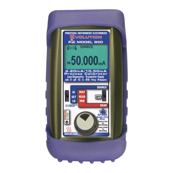
4-20mA/10-50mA
4-20mA/10-50mA
Process Calibrator
Process Calibrator
Loop Diagnostics • Transmitter Supply
Loop Diagnostics • Transmitter Supply
mA • V • pH •TC • Ohms • RTD • Freq • Pressure
mA • V • pH •TC • Ohms • RTD • Freq • Pressure
Operating Instructions
Operating Instructions
www.
.com
information@itm
Advertisement
Table of Contents

Related Manuals for PIE 850


Summary of Contents for PIE 850
- Page 1 PIE 850 PIE 850 4-20mA/10-50mA 4-20mA/10-50mA Process Calibrator Process Calibrator Loop Diagnostics • Transmitter Supply Loop Diagnostics • Transmitter Supply mA • V • pH •TC • Ohms • RTD • Freq • Pressure mA • V • pH •TC • Ohms • RTD • Freq • Pressure...
-
Page 2: Table Of Contents
Contents General Operations Accessories ................3 Carrying Case, Boot & Changing Batteries ......4 Storing EZ-CHECK Outputs & Connections ......5 Basic Operation Switches & Knobs ............... 6, 7 MAIN Menus - Functions, Units & Ranges ......7, 8, 9 FEATURE Menu - Stepping & Ramping / Auto Off ....10 FEATURE Menu - Stepping &... - Page 3 Finds prob- lems with power supplies & loops with too many loads. Patented by PIE! Troubleshoot wiring problems without a multimeter Built in continuity checker with ‘beeper’ quickly finds broken wires or shorts in instrumentation wiring.
- Page 4 General Information The PIE Model 850 is more than a multifunction calibrator. It is also a loop detective that is able to diagnose common problems that other test equipment just can’t find. Have a flooded junction box or unknown ground faults? Our Loop Diagnostic technology will detect it.
-
Page 5: Accessories
Evolution Hands Free Carrying Case Part No. 020-0211 (Evolution Hands Free Carrying Case with Pressure Module Pocket, Part No. 020-0233, will replace the 020-0211 when the Model 850 is ordered with at least one pressure module) Blue Rubber Boot Part No. 020-0213 Test Leads - one pair with Part No. - Page 6 FIELD & BENCH USE PIE 850 comes with a carrying case designed for hands-free operation and a rubber boot with a built-in tilt stand. The PIE 850 is held in the case by elastic straps for use with the carrying case open.
- Page 7 SET position on the EZ-CHECK switch. Connections PIE 850 has banana jacks compatible with unshielded or retractable banana plugs. Included with your calibrator are a pair of test leads with alligator clips for mA, V, pH & Hz connections.
-
Page 8: Basic Operation
The values stored in the HI and LO positions are also used for Auto Stepping. READ: Slide the switch to the SET position. The PIE 850 will display the current reading from the sensor or device being measured. Slide the switch to MAX and the highest value measured since turn-on or reset will be displayed;... - Page 9 MAX readings which will update as the input value changes. SELECTING FUNCTIONS The EZ-DIAL knob is used to setup the PIE 850 to match the instrument to be calibrated or signal to be measured. Each time you turn on the PIE 850 the LCD displays the screen below for about 1 second followed by operating in the function used the last time it was operated.
-
Page 10: Simulate 2 Wire Transmitters
Operating Instructions Double Click Menus - MAIN Page Double click the EZ-DIAL knob to access the Double Click Menus. Shown are the MAIN menus for each function. Turn the knob to scroll thru the menus and press the knob to select. Default settings are represented in black and other choices in grey. - Page 11 Operating Instructions Double Click Menus - MAIN Page Source & Read Thermocouples > EXIT FUNCTION UNITS °C °F T/C TYPE K E T R S B N L U G C D P COLD JUNC Source RTD > EXIT FUNCTION UNITS °C °F...
- Page 12 Operating Instructions Double Click Menu - FEATURES To change the Automatic Stepping settings Double click the DIAL KNOB at any time the unit is on and the following typical display (will be different for each FUNCTION) will appear for 15 seconds: MAIN >...
- Page 13 Operating Instructions Double Click Menu - FEATURES STEPS/RAMP - pressing the knob will cycle through 2, 3, 5, 11 and RAMP. The endpoints of the steps or ramp are based on the values stored in the HI and LO EZ-CHECK outputs. 2 steps will automatically switch between the values stored in the HI &...
- Page 14 Operating Instructions Choose 4-20 mA or 10-50 mA operation. Works with SOURCE mA, Read mA and Simulate 2-Wire Transmitters. Move the power switch to SOURCE or READ and Double click the DIAL KNOB and the MAIN menu for the function in use will appear for 15 seconds: MAIN >...
- Page 15 PWRM is POWER MEASURE which uses the internal loop supply of the 850 to power up the transmitter while indicating the current passing through the loop proportional to the input of transmitter which is controlled by the output of the 850.
- Page 16 When enabled the LOOPSCOPE also indicates errors by flashing the LED and writing diagnostic messages on the display. Messages include LOW LOOP VOLT, HIGH LOOP VOLT and HIGH LOOP IMPED. With LOOPSCOPE on the 850 occasionally performs a test which affects the loop mA signal. 2-WIRE 2-WIRE 25.4 V...
- Page 17 2 Wire SIM mA, 2 Wire SIM % (Percent of 4-20 or 10-50 mA) Connect the output leads of the PIE 850 to the inputs of the device being calibrated, making sure to check polarity. Red lead to the plus (+) input and black lead to the minus (-) input.
- Page 18 (250Ω resistor is only available in 4-20mA operation). Connect the output leads of the PIE 850 to the inputs of the device being calibrated, making sure to check polarity. Red lead to the plus (+) input and black lead to the minus (-) input.
- Page 19 (250Ω resistor is only available in 4-20mA operation). Connect the red input lead (+) of the PIE 850 to the more positive point of the break and the black input lead (-) to the more negative point.
- Page 20 (+) input of the device and the black source lead to the minus (-). The PIE 850 supplies a nominal 24 volts DC at 24 mA or 40 volts DC at 52 mA to the 2 Wire Transmitter. The current passed by the transmitter will be accurately displayed by the PIE 850.
-
Page 21: Using Ground Leak Detection
Turn on the LEAK DETECT. 4) Connect the red source lead from the mA (+) jack of the 850 to the plus (+) input of the device and the black source lead from the mA (-) to the minus (-). -
Page 22: Using Ground Leak Detection
Transmitter Typical Error Conditions PWRM LEAK PWRM LEAK 00.28 mA 12.280 24.999 The PIE 850 is supplying The PIE 850 is supplying the loop voltage. There is a loop voltage. control loop error. This may calibrated transmitter is be a transmitter (set for... -
Page 23: Source V & Mv; Read V & Mv
Select V for the FUNCTION and 1 V, 10V or 100 mV for the RANGE. Connect the output leads of the PIE 850 to the inputs of the device being calibrated, making sure to check polarity. Red lead to the plus (+) input and black lead to the minus (-) input. - Page 24 Select V for the FUNCTION and 1V, 10V, 60V or 100 mV for the RANGE. Connect the red input lead (+) of the PIE 850 to the more positive point of the break and the black input to the more negative point.
- Page 25 Connect the output leads of the PIE 850 to the inputs of the device being calibrated, making sure to check polarity. Red lead from the mV (+) jack of the 850 to the plus (+) input and black lead from the mV (-) jack to the minus (-) input.
- Page 26 0.000 to 14.000 pH @ 25°C corresponding to 414.12 to -414.12 mV. Once the pH instrument has been adjusted against the PIE 850 reconnect the pH probe and check it against the proper buffer (typically 7 pH). If the instrument zero point requires more than the manufacturer’s recommendations (typically within 0.5 pH) it...
- Page 27 (J, K, E, T, R, S, B, N, L (J-DIN), U (T-DIN), G, C, D or P (Platinel II)) and internal COLD JUNC ON or OFF (ON is the default). Connect the PIE 850 to the inputs of the device being calibrated using the proper type of thermocouple wire via the miniature thermocouple socket.
- Page 28 T/C Type (J, K, E, T, R, S, B, N, L (J-DIN), U (T-DIN), G, C, D or P (Platinel II)) and COLD JUNC ON or OFF (ON is the default). Connect the PIE 850 to the inputs of the device being calibrated using the proper type of thermocouple wire via the miniature thermocouple socket.
-
Page 29: Resistance
Select OHMS for the FUNCTION, 400Ω or 4000Ω for the RANGE. Disconnect all sensor wires from the devices to be calibrated and connect the PIE 850 to the inputs of the device using 2, 3 or 4 wires. Instantly output your SPAN and ZERO output settings by moving the EZ-CHECK switch between HI and LO. - Page 30 “OVER RANGE” flashed on the display and the OVERLOAD LED blinks red. The PIE 850 measures the input signal and constantly updates the display with the current reading. Move the EZ-CHECK switch to MAX to see the highest reading and to MIN to see the lowest reading.
- Page 31 RTD type. Disconnect all sensor wires from the devices to be calibrated and connect the PIE 850 to the inputs of the device using 2, 3 or 4 wires. Instantly output your SPAN and ZERO output settings by moving the EZ-CHECK switch between HI and LO.
- Page 32 “OVER RANGE” flashed on the display and the red OVERLOAD LED lit. The PIE 850 measures the input signal and constantly updates the display with the current reading. Move the EZ-CHECK switch to MAX to see the highest reading and to MIN to see the lowest reading.
-
Page 33: Frequency
2000CPM for the RANGE. Disconnect all input wires from the devices to be calibrated and connect the PIE 850 to the input of the device matching polarity. The green HZ SYNC LED pulses in synch with the output pulses and may be used to calibrate optical pickups. -
Page 34: Frequency
Select FREQ for the FUNCTION and 20KHZ, 10000HZ, 1000HZ or 2000CPM for the RANGE. Disconnect all input wires from the devices to be calibrated and connect the PIE 850 to the output of the device matching polarity. The green HZ SYNC LED pulses in synch with the input frequency. -
Page 35: Read Pressure
2) Remove the covers from the ends of the connector on the pressure module cable and the pressure connector of the 850. Align the white arrows and plug the cable into the 850. 3) Connect pressure hoses, fittings & pumps (if required) to the pressure instrument to be checked. - Page 36 PIE 850 with Pressure Module, Pressure/Vacuum Pump & Hose Hands free carrying case with pockets for the PIE 850 and the pressure module. Back of the case has a zippered pocket for the manual, test leads, hoses and pressure fittings.
- Page 37 Optional Pressure Modules Sensor Code Application DNxxxx Differential, Non-isolated 0 to 0010*, 0028, 0200, 0415, 2000” H2O DIxxxx Differential, Isolated 0 to 0001, 0005, 0015, 0030, 0100, 0300, 0500 PSID GIxxxx Gauge, Isolated 0 to 0015, 0030, 0050, 0100, 0300, 0500, 1000, 3000 PSIG CIxxxx Compound, Isolated -14.7 to +0015, 0030, 0050, 0100, 0300, 0500, 1000, 3000...
-
Page 38: Specifications
Specifications General Operating Temp Range -20 to 60 °C (-5 to 140 °F) Storage Temp Range -30 to 60 °C (-22 to 140 °F) Temperature effect ≤ ± 0.01 %/°C of Full Scale Relative Humidity 10 % ≤RH ≤90 % (0 to 35 °C), Non-condensing Range 10 % ≤RH≤... - Page 39 Specifications Read mA Ranges and Resolution 0.000 to 24.000 mA or -25.00 to 125.00% of 4-20 mA, 0.000 to 52.000 mA or -25.00 to 105.00% of 10-50 mA Accuracy ≤ ± (0.02 % of Reading + 0.003 mA) Voltage burden ≤...
- Page 40 Specifications Source V dc Ranges and Resolution -20.000 to 99.999 mV, -500.00 to 999.99 mV, 0.000 to 10.250V Accuracy ≤ ± (0.02 % of Reading + 0.01% Full Scale) Source Current ≥ 20 mA Sink Current > 16 mA Output Impedance <...
- Page 41 Specifications RTD, OHMS and Continuity Read Resistance Ranges 0.00 to 401.00, 0.0 to 4010.0 Ohms Accuracy ±(0.025% of Reading + 0.075 Ohms) Excitation Current 1.0 mA to 401 Ohms, 0.5 mA to 4010 Ohms (nominal) Continuity 0.0 to 401.0 Ohms; Beeps from 0.0 to 100.0 Ohms RTD and OHMS Source 3 Wire &...
- Page 42 Specifications Frequency Source Ranges 1 to 2000 CPM, 0.01 to 999.99 Hz, 0.1 to 9999.9 Hz, 0.001 to 20.000 kHz Accuracy ± (0.02 % of Reading + 0.01% Full Scale) Output Waveform Square Wave, Zero Crossing -1.0 to +5 V peak-to-peak ±10% Risetime (10 to 90% of <...
-
Page 43: Thermocouple Ranges & Accuracies
Thermocouple Ranges & Accuracies Based on ≤ ± (0.02 % of Reading + 0.01 mV) Degrees C °C Degrees F °F Range Range -200.0 to -50.0 ±0.5° -328.0 to -58.0 ±1.0° -50.0 to 300.0 ±0.2° -58.0 to 572.0 ±0.4° 300.0 to 900.0 ±0.3°... -
Page 44: Thermocouple Ranges & Accuracies
662.0 to 2912.0 ±2.0° 1600.0 to 1767.8 ±1.3° 2912.0 to 3214.0 ±2.4° 315.6 to 600.0 ±3.2° 600.0 to 1122.0 ±5.7° 600.0 to 850.0 ±1.7° 1122.0 to 1562.0 ±3.1° 850.0 to 1100.0 ±1.3° 1562.0 to 2012.0 ±2.4° 1100.0 to 1820.0 ±1.1°... - Page 45 Thermocouple Ranges & Accuracies Based on ≤ ± (0.02 % of Reading + 0.01 mV) Degrees C °C Degrees F °F Range Range -1.1 to 150.0 ±1.0° 30.1 to 302.0 ±1.8° 150.0 to 1100.0 ±0.7° 302.0 to 2012.0 ±1.3° 1100.0 to 1750.0 ±1.0°...
-
Page 46: Rtd Ranges & Accuracies
DIN/IEC/JIS 1989 0.0 to 340.0 ±0.3° 248.0 to 644.0 ±0.6° 1.3850 (ITS-90) 340.0 to 640.0 ±0.4° 644.0 to 1184.0 ±0.8° 640.0 to 850.0 ±0.5° 1184.0 to 1562.0 ±1.0° Pt 100 Ohm -200.0 to 10.0 ±0.2° -328.0 to 50.0 ±0.4° (Burns) 10.0 to 350.0... - Page 47 (3) years or a minimum of one (1) year from the date of shipment. Additional Information PIE Calibrators are manufactured in the USA. This product is calibrated on equipment traceable to NIST and includes a Certificate of Calibration. Test Data is available for an additional charge.
Need help?
Do you have a question about the 850 and is the answer not in the manual?
Questions and answers