Table of Contents
Troubleshooting

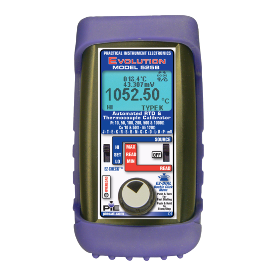
Related Manuals for PIE 525B


Summary of Contents for PIE 525B
- Page 1 PIE 525B PIE 525B Automated Thermocouple & Automated Thermocouple & RTD Calibrator RTD Calibrator Operating Instructions Operating Instructions 99 Washington Street Melrose, MA 02176 800.517.8431 TestEquipmentDepot.com...
-
Page 2: Table Of Contents
Contents General Operations Connections ................4 Accessories ................5 Carrying Case, Boot..............6 Changing Batteries & Storing EZ-CHECK Outputs ....7 Basic Operation Switches & Knobs ..............8-9 MAIN Menus - Functions, Units & Ranges ...... 10-11 FEATURE Menu - Stepping & Ramping / Auto Off ....12 FEATURE Menu - Stepping &... - Page 3 General Information Calibrate all your T/C & RTD Instruments • Easy to use With the PIE 525B you can check and calibrate all your thermocouple and RTD instruments and measure temperature sensors. • Take it into the shop, plant or field Carry it without worry - it comes protected with a rubber boot and rugged, low profile switches.
- Page 4 AMS 2750 as a Secondary Standard & as a Field Test Instrument. • Measure thermocouple & RTD sensors The PIE 525B measures probes to 0.1 or 0.01 °C or °F. Secondary display shows the millivolt or resistance value corresponding to the sensor...
- Page 5 OPEN TC on the display. Troubleshoot RTD sensor connections and find broken wires with patented technology. Connect your two, three or four wire RTDs and the PIE 525B automatically detects the connections. • Calibration Lab Accurate & Stable The internal cold junction thermistor is accurate to ±0.05°C and is traceable to NIST.
-
Page 6: Connections
Plug thermocouple wires into the miniature jack or place bare thermocouple wires onto the brass block under the screws. The PIE 525B has two banana jacks (1+ & 2-) mounted in the top end of the housing. These are not temperature compensated and are to be used only for millivolt signals or thermocouple signals with the cold junction turned off. -
Page 7: Accessories
Accessories INCLUDED: Four “AA” Alkaline batteries, Certificate of Calibration Evolution Hands Free Carrying Case Part No. 020-0211 Dark Blue Rubber Boot Part No. 020-0213 Test Leads - one pair with Part No. 020-0207 banana plug & alligator clips Evolution RTD Wire Kit Part No. -
Page 8: Carrying Case, Boot
PIE 525B comes with a carrying case designed for hands-free operation and a rubber boot with a built-in tilt stand. The PIE 525B is held in the case by elastic straps for use with the carrying case open. The tilt stand is easily raised by pulling the stand until it locks into place. -
Page 9: Changing Batteries & Storing Ez-Check Outputs
Low battery is indicated by a battery symbol on the display. Approximately one to four hours of typical operation remain before the PIE 525B will automatically turn off. To change the batteries remove the rubber boot and remove the battery door from the back of the unit by sliding the door downward. -
Page 10: Basic Operation
The values stored in the HI and LO positions are also used for Auto Stepping. READ: Slide the switch to the SET position. The PIE 525B will display the current reading from the sensor or device being measured. Slide the switch to MAX and the highest value measured since turn-on or reset will be displayed;... - Page 11 SELECTING FUNCTIONS The EZ-DIAL knob is used to setup the PIE 525B to match the instrument to be calibrated or signal to be measured. Each time you turn on the PIE 525B the LCD displays the following screen for about 1 second followed by operating in the function used the last time it was operated.
-
Page 12: Main Menus - Functions, Units & Ranges
Operating Instructions Double Click Menus - MAIN Page Double click the EZ-DIAL knob to access the Double Click Menus. Shown are the MAIN menus for each function. Turn the knob to scroll thru the menus and press the knob to select. Default values are in black and available choices are shown in grey. -
Page 13: Thermocouple
Operating Instructions Double Click Menu - DISPLAY Page Double click the DIAL KNOB at any time the unit is on and then turn the DIAL KNOB to move to the second menu page so the word DISPLAY appears at the top of the menu. Turn the DIAL KNOB to move through the menu. -
Page 14: Feature Menu - Stepping & Ramping / Auto Off
Operating Instructions Double Click Menu - FEATURES To change the Automatic Stepping settings Double click the DIAL KNOB at any time the unit is on and the following typical display (will be different for each FUNCTION) will appear for 15 seconds: MAIN >... -
Page 15: Feature Menu - Stepping & Ramping / Backlight
Operating Instructions Double Click Menu - FEATURES STEPS/RAMP - pressing the knob will cycle through 2, 3, 5, 11 and RAMP. The endpoints of the steps or ramp are based on the values stored in the HI and LO EZ-CHECK outputs. 2 steps will automatically switch between the values stored in the HI &... - Page 16 Select V for the FUNCTION. Connect the output leads of the PIE 525B to the inputs of the device being calibrated, making sure to check polarity. Red lead to the plus (+) input and black lead to the minus (-) input.
- Page 17 Select V for the FUNCTION. Connect the red input lead (+) of the PIE 525B to the more positive point and the black input lead (-) to the more negative point.
-
Page 18: Source T/C & Read T/C Sensors
(J, K, E, T, R, S, B, N, L (J-DIN), U (T-DIN), G, C, D or P (Platinel II)) and internal COLD JUNC ON or OFF (ON is the default). Connect the PIE 525B to the inputs of the device being calibrated using the proper type of thermocouple wire via the miniature thermocouple socket or place bare thermocouple leads under the brass screws. - Page 19 T/C Type (J, K, E, T, R, S, B, N, L (J-DIN), U (T-DIN), G, C, D or P (Platinel II)) and COLD JUNC ON or OFF (ON is the default). Connect the PIE 525B to the inputs of the device being calibrated using the proper type of thermocouple wire via the miniature thermocouple socket or place bare thermocouple leads under the brass screws.
-
Page 20: Source Resistance, Read Resistance
Select OHMS for the FUNCTION, 400Ω or 4000Ω for the RANGE. Disconnect all sensor wires from the devices to be calibrated and connect the PIE 525B to the inputs of the device using 2, 3 or 4 wires. Instantly output your SPAN and ZERO output settings by moving the EZ-CHECK switch between HI and LO. - Page 21 Select OHMS for the FUNCTION, 400Ω or 4000Ω for the RANGE. Connect the PIE 525B to the resistor or sensor using 2, 3 or 4 wires. The PIE 525B automatically detects how many wires are connected using a patented circuit and indicates each wire that is connected.
-
Page 22: Source Rtd & Read Rtd Sensors
Note: Platinum (Pt) 100Ω 3850 is the most common RTD type. Disconnect all sensor wires from the devices to be calibrated and connect the PIE 525B to the inputs of the device using 2, 3 or 4 wires. Instantly output your SPAN and ZERO output settings by moving the EZ-CHECK switch between HI and LO. - Page 23 Ohm). Note: Platinum (Pt) 100Ω 3850 is the most common RTD type. Connect the PIE 525B to the RTD sensor using 2, 3 or 4 wires. The PIE 525B automatically detects how many wires are connected using a patented circuit and indicates each wire that is connected.
-
Page 24: Troubleshooting Rtd Instruments
SENSOR mA ON. Disconnect all sensor wires from the devices to be calibrated and connect the PIE 525B to the inputs of the device using 2, 3 or 4 wires. The sensor current generated by the instrument will be indicated on the display followed by the word FIXED or PULSE. - Page 25 Instrument with RTD Input Controller Temperature Transmitter Temperature Indicator Temperature Trip or Alarm 01.15mA PULSE 2 4 1 289.27 525.00 °c α Pt 100 =3850 Automated RTD & Thermocouple Calibrator Pt 10, 50, 100, 200, 500 & 1000Ω Cu 10 & 50Ω · Ni 120 J ·...
-
Page 26: Troubleshooting Rtd Sensors
The PIE 525B automatically detects 2, 3 and 4 wire RTD connections with a patented circuit. It will also display the connections on the display and indicate when there is a missing connection due to a loose connector, corrosion or a broken wire. - Page 27 Page 25...
-
Page 28: Specifications
PIE 525B Specifications Unless otherwise indicated all specifications (except Cold Junction) are rated from a nominal 23 °C, 70 % RH for 1 year from calibration General Operating -20 to 60 °C (-5 to 140 °F) Temperature Range Storage -30 to 60 °C (-22 to 140 °F) - Page 29 PIE 525B Specifications Protection Over-voltage protection to 60 vrms (rated for against 30 seconds) misconnection Red LED indicates OVERLOAD or out of range conditions Display High contrast graphic liquid crystal display. LED backlighting for use in low lit areas. Voltage Source Ranges and -13.000 to 80.000 mV &...
- Page 30 PIE 525B Specifications Thermocouple Source Accuracy ±(0.008% of Setting + 0.006 mV) Cold Junction ± 0.09°F (±0.05 °C) - Thermistor traceable to Compensation NIST for 11 years Output < 0.3 Ohms Impedance Source Current > 10 mA (drives 80 mV into 10 Ohms) RMS Noise ≤...
- Page 31 PIE 525B Specifications RTD and Ohms Source 3 Wire & 4 Wire Accuracy From 1 to 10.2 mA ±(0.015% of Setting + 0.05 Ohms) External Excitation Current Below 1 mA of 0.025 mV Add ( ) to Accuracy External Excitation...
-
Page 32: Thermocouple Ranges & Accuracies
Thermocouple Ranges & Accuracies Table based on Accuracy: ≤ ± (0.008 % of Reading + 0.006 mV) Note: Doesn’t include cold junction error of ±0.05°C Degrees C °C Degrees F °F Range Range -200.00 to -150.00 ±0.25° -328.00 to -238.00 ±0.55°... -
Page 33: Thermocouple Ranges & Accuracies
Thermocouple Ranges & Accuracies Table based on Accuracy: ≤ ± (0.008 % of Reading + 0.006 mV) Note: Doesn’t include cold junction error of ±0.05°C Degrees C °C Degrees F °F Range Range -18.30 to 250.00 ±1.26° -1.00 to 482.00 ±2.27°... - Page 34 Thermocouple Ranges & Accuracies Table based on Accuracy: ≤ ± (0.008 % of Reading + 0.006 mV) Note: Doesn’t include cold junction error of ±0.05°C Degrees C °C Degrees F °F Range Range 100.00 to 450.00 ±1.14° 212.00 to 842.00 ±2.05°...
- Page 35 Thermocouple Ranges & Accuracies Table based on Accuracy: ≤ ± (0.008 % of Reading + 0.006 mV) Note: Doesn’t include cold junction error of ±0.05°C DIN Wire Degrees C °C Degrees F °F Range Range -200.00 to -100.00 ±0.21° -328.00 to -148.00 ±0.38°...
-
Page 36: Rtd Ranges & Accuracies
RTD Ranges & Accuracies Table based on 3 & 4 Wire RTD (ITS-90) Accuracy*: ≤ ± (0.015 % of Reading +0.05 Ohms) Degrees C Degrees F Type Range °C Range °F Pt 100 Ohm -200.00 to -150.00 ±0.13° -328.0 to -238.00 ±0.24°... -
Page 37: Rtd Ranges & Accuracies
RTD Ranges & Accuracies Table based on 3 & 4 Wire RTD (ITS-90) Accuracy*: ≤ ± (0.015 % of Reading +0.05 Ohms) Degrees C Degrees F Type Range °C Range °F Pt 100 -195.61 to -100.00 ±0.14° -320.10 to -148.00 ±0.26°... - Page 38 Guaranteed compatible with smart transmitters, multichannel recorders as well as PLC and DCS input cards. Page 36...
- Page 39 (3) years or a minimum of one (1) year from the date of shipment. Additional Information PIE Calibrators are manufactured in the USA. This product is calibrated on equipment traceable to NIST and includes a Certificate of Calibration. Test Data is available for an additional charge.
- Page 40 99 Washington Street Melrose, MA 02176 800.517.8431 TestEquipmentDepot.com...
Need help?
Do you have a question about the 525B and is the answer not in the manual?
Questions and answers