
Related Manuals for IFM Electronic ZB0050


Summary of Contents for IFM Electronic ZB0050
- Page 1 Operating instructions Safety Rope Emergency Stop Switches ZB0050 / ZB0051 ZB0070 / ZB0071 ZB0075...
-
Page 2: Table Of Contents
5.1 Maintenance requirement ..................8 6 Electrical connection ....................9 7 Safety characteristics ....................12 8 Technical data ZB0050 / ZB0051 / ZB0071 ............. 13 8.1 Technical data ZB0070 / ZB0075 ............... 14 9 Scale drawing ......................15 10 Accessories ......................15 11 Standards ...................... -
Page 3: Safety Instructions
Safety instructions Follow the operating instructions. Non-observance of the instructions, operation which is not in accordance with use as prescribed below, wrong installation or incorrect handling can affect the safety of operators and machinery. For installation and prescribed use of the product the notes in the operating instructions must be carefully observed and the applicable technical standards relevant for the application have to be considered. -
Page 4: Installation / Set-Up
Installation / set-up Applications The safety rope emergency stop switch is used to provide safety-related switching statuses where large danger areas have to be secured and housings or covers are not possible. Typical applications are conveyor systems and rotating machines and large danger areas. -
Page 5: Operating And Display Elements
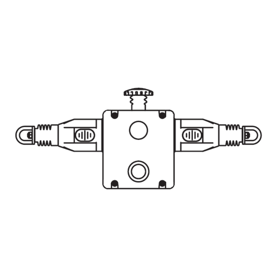
Operating and display elements 1: red E-stop 2: blue reset button 3: dual LED (ZB0051, ZB0070, ZB0071, ZB0075) 4: rope tension indicator Rope tension indicator: Indicator shown with steel rope properly adjusted... -
Page 6: Installation
4 Installation Installation must be carried out by authorised personnel. The safety rope emergency stop switch is mounted using four M5 screws. The tightening torque for the fixing screws is 4 Nm The tightening torque for the cover screws, the cable glands and cable seals is 1.5 Nm to ensure protection rating IP 67. - Page 7 The switches are equipped with a red, mushroom-shaped E-stop button. Check the individual emergency stop switches and reset them to ensure proper functioning of the control circuits. The typical operating conditions for a successful operation of the safety rope emergency stop system are: max.
-
Page 8: Function
5 Function Pulling the tensioned rope, rope breakage or impact on the E-stop cause activation of the switching function of the safety rope emergency stop switch. There is a window on the switch via which the correct rope tension can be monitored during setting and maintenance. -
Page 9: Electrical Connection
6 Electrical connection Wiring is only possible if the device is disconnected from power. Contact arrangement 0 mm 4.0 mm 15.0 mm 17.0 mm 4 NC + 2 NO Rope slack Tension range Rope pulled 11/12 21/22 33/34 41/42 51/52 63/64 ... - Page 10 Installation sample: Programming sample: Data bits: Data bit In/Out SI-2 SI-2 SI-1 SI-1/O-1 Activated input channel Bit sequence D3-D0 SI-1 XX00 SI-2 00XX SI-1 and SI-2 0000 keiner XXXX Activated alarm outputs Bit sequence D3-D0 XXX1 X= random...
- Page 11 110 V AC LED: 110 V AC on terminal 1 (red) -> LED display flashing red 110 V AC on terminal 3(green) -> LED display permanently green 0V on terminal 2 (black) Installation sample:...
-
Page 12: Safety Characteristics
7 Safety characteristics Characteristics Value Performance level PL e Category cat. 4 (with appropriate monitoring) 214 years MTTF Mission time T 21 years Annual Usage 8 cycle per hour/24hours per day/365 days 1.5 • 10 cycles at 100mA load These calculations were made on the basis of an ambient temperature of 40 °C. The device meets the requirements of EN ISO 13849-1: 2008 category 4 / PL e and can be used in applications up to PL e. -
Page 13: Technical Data Zb0050 / Zb0051 / Zb0071
8 Technical data ZB0050 / ZB0051 / ZB0071 Electrical design Safety contacts 4 NC Auxiliary contact 2 NO Type of contact snap-action contacts Contact material silver Switching capacity AC: 240 V/3 A, 120 V/6 A, inductive DC: 24 V/2.5 A, inductive Max. -
Page 14: Technical Data Zb0070 / Zb0075
8.1 Technical data ZB0070 / ZB0075 Electrical design Safety contacts 4 NC Auxiliary contact 2 NO Type of contact snap-action contacts Contact material silver Switching capacity AC: 240 V/3 A, 120 V/6 A, inductive DC: 24 V/2.5 A, inductive Max. switching voltage/switching capacity 240 V/720 VA Minimum load 5 V, 5 mA DC... -
Page 15: Scale Drawing
9 Scale drawing Dimension in mm 10 Accessories ZB0052: Safety rope e-stop switch with left sided rope connection, LED 24 V DC ZB0053: Safety rope e-stop switch with right sided rope connection, LED 24 V DC ZB0072: Safety rope e-stop switch with left sided rope connection, LED 110 V AC ZB0073: Safety rope e-stop switch with right sided rope connection, LED 110 V AC ZB0054: Rope tensioner kit, stainless steel, rope length 5 m ZB0055: Rope tensioner kit, stainless steel, rope length 10 m... -
Page 16: Standards
Standards The following standards and directives have been applied: • Machinery Directive 2006/42/EC • EN ISO 13849-1: 2008 • EN ISO 13850: 2008 • AS/NSZ 4024.1 - 2014 • IEC / EN 60947-5-1: 2004: +A1: 2009 • IEC / EN 60947-5-5: 1998 + A11: 2013 •... -
Page 17: Approvals / Certificates
Approvals / certificates EC declaration of conformity • TÜV Rheinland (pending) • UL (cULus) • AS/NSZ 4024.1 •... - Page 18 • 930 Great South Road Penrose, Auckland • Tel. +64 95 79 69 91 ifm electronic s.a. • 4410-136 São Félix da Marinha • Tel. +351 223 / 71 71 08 ifm electronic Sp. z o.o. • 40-524 Katowice • Tel. +48 32-608 74 54 RA ROU ifm electronic s.r.l.
Need help?
Do you have a question about the ZB0050 and is the answer not in the manual?
Questions and answers