
Related Manuals for IFM Electronic ZB0052


Summary of Contents for IFM Electronic ZB0052
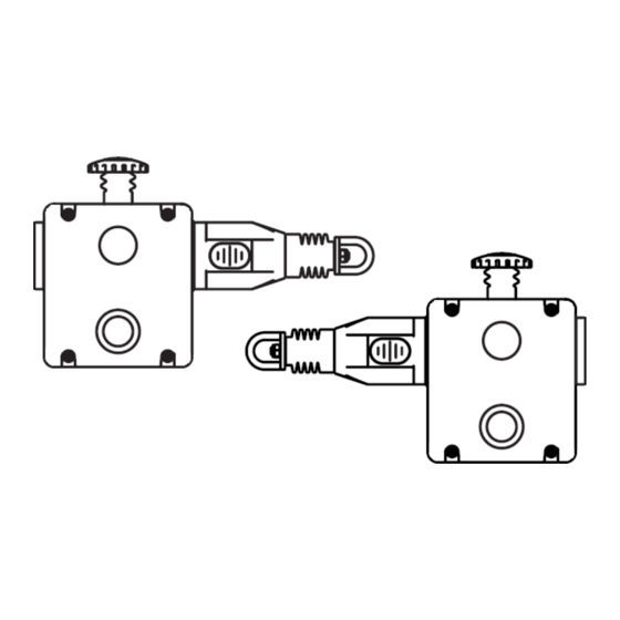
- Page 1 Operating instructions Safety Rope Emergency Stop Switches ZB0052 / ZB0053 ZB0072 / ZB0073...
-
Page 2: Table Of Contents
Contents 1 Safety instructions ..................... 3 2 Installation / set-up ....................4 2.1 Applications......................4 2.2 Function and electrical connection ...............4 3 Operating and display elements ................5 4 Installation ......................... 6 5 Function ........................8 5.1 Maintenance requirement ..................8 6 Electrical connection .................... -
Page 3: Safety Instructions
Safety instructions Follow the operating instructions. Non-observance of the instructions, operation which is not in accordance with use as prescribed below, wrong installation or incorrect handling can affect the safety of operators and machinery. For installation and prescribed use of the product the notes in the operating instructions must be carefully observed and the applicable technical standards relevant for the application have to be considered. -
Page 4: Installation / Set-Up
Installation / set-up Applications The safety rope emergency stop switch is used to provide safety-related switching statuses where large danger areas have to be secured and housings or covers are not possible. Typical applications are conveyor systems and rotating machines and large danger areas. -
Page 5: Operating And Display Elements
Operating and display elements 1: red E-stop 2: blue reset button 3: dual LED 4: rope tension indicator Rope tension indicator: Indicator shown with steel rope properly adjusted... -
Page 6: Installation
Installation Installation must be carried out by authorized personnel. The safety rope emergency stop switch is mounted using four M5 screws. The tightening torque for the fixing screws is 4 Nm The tightening torque for the cover screws, the cable glands and cable seals are 1.5 Nm to ensure protection rating IP 67. - Page 7 The tension of the rope is obtained by rope tensioner systems. After the installation the tension must be set to the middle position which is indicated by green arrows in the transparent window of the individual switches. Verify the function of all switches and the control circuits by pulling on various spots on the rope in the active protected area and then resetting the individual switches by pressing the blue reset button.
-
Page 8: Function
Function Pulling the tensioned rope, rope breakage or impact on the E-stop cause activation of the switching function of the safety rope emergency stop switch. There is a window on the switch via which the correct rope tension can be monitored during setting and maintenance. -
Page 9: Electrical Connection
Electrical connection Wiring is only possible if the device is disconnected from power. Contact arrangement 0 mm 3.5 mm 14.5 mm 17.0 mm 4 NC + 2 NO Rope slack Tension range Rope pulled 11/12 21/22 33/34 41/42 51/52 63/64 ... - Page 10 Installation sample: Programming sample: Data bits: Data bit In/Out SI-2 SI-2 SI-1 SI-1/O-1 Activated input channel Bit sequence D3-D0 SI-1 XX00 SI-2 00XX SI-1 and SI-2 0000 none XXXX Activated alarm outputs Bit sequence D3-D0 XXX1 X= random...
- Page 11 110 V AC LED: 110 V AC on terminal 1 (red) -> LED display flashing red 110 V AC on terminal 3(green) -> LED display permanently green 0V on terminal 2 (black) Installation sample:...
-
Page 12: Safety Characteristics
Safety characteristics Characteristics Value 1.5 • 10 cycles at 100mA load ISO 13849-1 Up to PL depending upon system architecture Up to SIL3 depending upon system architecture EN 62061 8 cycle per hour/24hours per day/365 days Annual Usage MTTF 214 years The safety rope switch may be used as part of the safety related control system to perform the emergency stop function in accordance with EN 13850. -
Page 13: Technical Data
Technical data Electrical design Safety contacts 4 NC Auxiliary contact 2 NO Type of contact snap-action contacts Contact material silver Switching capacity AC: 240 V/3 A, 120 V/6 A, inductive DC: 24 V/2.5 A, inductive Max. switching voltage/switching capacity 240 V/720 VA Minimum load 5 V, 5 mA DC Thermal current... -
Page 14: Scale Drawing
9 Scale drawing ZB0052 / ZB0072 Dimension in mm ZB0053 / ZB0073 Dimension in mm... -
Page 15: Accessories
Accessories ZB0050: Safety rope e-stop switch with dual sided rope connection ZB0051: Safety rope e-stop switch with dual sided rope connection, LED 24 V DC ZB0071: Safety rope e-stop switch with dual sided rope connection, LED 110 V AC ZB0054: Rope tensioner kit, stainless steel, rope length 5 m ZB0055: Rope tensioner kit, stainless steel, rope length 10 m ZB0056: Rope tensioner kit, stainless steel, rope length 20 m ZB0057: Rope tensioner kit, stainless steel, rope length 50 m... -
Page 16: Standards
Standards The following standards and directives have been applied: • Machinery Directive 2006/42/EC • EN ISO 13850: 2015 • EN 60947-5-1: 2017 • EN 60947-5-5: 1997 + A2: 2017 • EN 60204-1: 2018 • AS/NSZ 4024.1 - 2014 • UL 508 Information with regard to UL 508: Type 1 Enclosures. -
Page 17: Approvals / Certificates
Approvals / certificates EC declaration of conformity • UL (cULus) • AS/NSZ 4024.1 •... - Page 18 CN ifm electronic (Shanghai) Co. Ltd. • 201203 Shanghai • Tel. +86 / 21 3813 4800 CZ ifm electronic, spol. s r.o. • 140 00 Praha 4 • Tel. +420 / 26 79 90 21 1 DK ifm electronic a/s • 2605 Brøndby • Tel. +45 / 70 20 11 08 ES ifm electronic s.l.
Need help?
Do you have a question about the ZB0052 and is the answer not in the manual?
Questions and answers