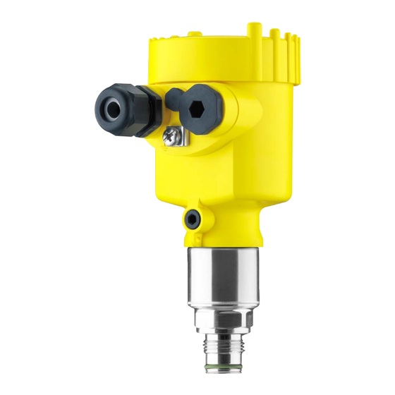
Vega VEGABAR 83 Quick Setup Manual
Pressure transmitter with metallic measuring cell
Hide thumbs
Also See for VEGABAR 83:
- Operating instructions manual (108 pages) ,
- Quick setup manual (24 pages) ,
- Product information (16 pages)

Related Manuals for Vega VEGABAR 83


Summary of Contents for Vega VEGABAR 83
-
Page 1: Quick Setup Guide
Quick setup guide Pressure transmitter with metallic measuring cell VEGABAR 83 4 … 20 mA Document ID: 46312... - Page 2 Operating Instructions Manual as well as the Safety Manual that comes with instruments with SIL qualification. These manuals are available in the download area of "www.vega.com". Operating instructions VEGABAR 83 - 4 … 20 mA: Document-ID 45033 Editing status of the quick setup guide: 2016-07-01 VEGABAR 83 • 4 … 20 mA...
-
Page 3: Authorised Personnel
During work on and with the device the required personal protective equipment must always be worn. Appropriate use The VEGABAR 83 is a pressure transmitter for process pressure and hydrostatic level measurement. You can find detailed information about the area of application in chapter "Product description". Operational reliability is ensured only if the instrument is properly used according to the specifications in the operating instructions manual as well as possible supplementary instructions. -
Page 4: Permissible Process Pressure
That is why we have introduced an environment management system with the goal of continuously improving company environmental pro- tection. The environment management system is certified according to DIN EN ISO 14001. Please help us fulfil this obligation by observing the environmental instructions in this manual: • Chapter "Packaging, transport and storage" • Chapter "Disposal" VEGABAR 83 • 4 … 20 mA... -
Page 5: Configuration
Go to "www.vega.com", "VEGA Tools" and "Instrument search". Enter the serial number. Alternatively, you can access the data via your smartphone: • Download the smartphone app "VEGA Tools" from the "Apple App Store" or the "Google Play Store" • Scan the Data Matrix code on the type label of the instrument or •... -
Page 6: Mounting 3.1 General Instructions For Use Of The Instrument
Housing aluminium Housing of stainless steel, electro-polished Filter element With the following instruments a blind plug is installed instead of the filter element: • Instruments in protection IP 66/IP 68 (1 bar) - ventilation via capil- laries in non-detachable cable • Instruments with absolute pressure VEGABAR 83 • 4 … 20 mA... -
Page 7: Connecting To Power Supply 4.1 Connecting
Fig. 3: Connection steps 5 and 6 - Single chamber housing 6. Insert the wire ends into the terminals according to the wiring plan Information: Solid cores as well as flexible cores with wire end sleeves are insert- ed directly into the terminal openings. In case of flexible cores without end sleeves, press the terminal from above with a small screwdriver, the terminal opening is then free. When the screwdriver is released, the terminal closes again. VEGABAR 83 • 4 … 20 mA... -
Page 8: Single Chamber Housing
Electronics and terminal compartment 4...20mA Fig. 4: Electronics and terminal compartment, single chamber housing Voltage supply, signal output For display and adjustment module or interface adapter Ground terminal for connection of the cable screen VEGABAR 83 • 4 … 20 mA... -
Page 9: Set Up With The Display And Adjustment Module 5.1 Insert Display And Adjustment Module
Note: If you intend to retrofit the instrument with a display and adjustment module for continuous measured value indication, a higher lid with an inspection glass is required. Parameter adjustment - Quick setup To quickly and easily adapt the sensor to the application, select the menu item "Quick setup" in the start graphic on the display and adjustment module. VEGABAR 83 • 4 … 20 mA... - Page 10 4. Position correction urement In this menu item you compensate the influence of the installation position of the instrument (offset) on the measured value. 5. Max. adjustment In this menu item you carry out the max. adjustment for level Enter the percentage value and the corresponding value for the max. level. VEGABAR 83 • 4 … 20 mA...
-
Page 11: Parameter Adjustment - Extended Adjustment
"Setup" should be selected one after the other and provided with the correct parameters. If possible, go through the items in the given sequence. The procedure is described below. The following submenu points are available: The submenu points described below. VEGABAR 83 • 4 … 20 mA... - Page 12 Ceramic measuring cell: Measuring cell tempera- ture in °C Metallic measuring cell: Electronics temperature in °C Display format 1 and 2 Number of positions after the decimal point, auto- matically Switched on Backlight Menu - Diagnosis Menu item Parameter Default setting Sensor status VEGABAR 83 • 4 … 20 mA...
- Page 13 0 … 100 °C correspond to 4 … 20 mA Menu - Info Menu item Parameter Device name Device name Instrument version Hardware and software version Factory calibration Date date Sensor characteristics Order-specific characteristics VEGABAR 83 • 4 … 20 mA...
-
Page 14: Supplement 6.1 Technical Data
16 … 30 V DC Ʋ Ex-d-ia instrument No lighting (integrated ia barrier) Reverse voltage protection Integrated Permissible residual ripple - Non-Ex, Ex-ia instrument Ʋ for U 12 V DC (9.6 V< U < 14 V) ≤ 0.7 V (16 … 400 Hz) IP 66/IP 68 (0.2 bar), only with absolute pressure VEGABAR 83 • 4 … 20 mA... - Page 15 Permissible residual ripple - Ex-d-ia instrument Ʋ for U 24 V DC (18 V< U < 35 V) ≤ 1 V (16 … 400 Hz) Load resistor Ʋ Calculation )/0.022 A Ʋ Example - Non-Ex instrument with (24 V - 9.6 V)/0.022 A = 655 Ω = 24 V DC VEGABAR 83 • 4 … 20 mA...
- Page 16 Subject to change without prior notice © VEGA Grieshaber KG, Schiltach/Germany 2016 VEGA Grieshaber KG Phone +49 7836 50-0 Am Hohenstein 113...
Need help?
Do you have a question about the VEGABAR 83 and is the answer not in the manual?
Questions and answers