Advertisement
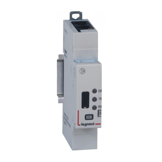
EMS CX
- Modbus/EMS Interface
3
1. DESCRIPTION - USE
. Module dedicated to Energy Management System (EMS CX
. It performs conversion from the EMS CX
protocol.
Symbol:
2. RANGE
. Cat. n° 4 149 40: EMS CX
/Modbus RS485 Interface
3
Width:
. 1 module. 17,8 mm width.
3. OVERALL DIMENSIONS
Technical data sheet: F02338EN/01
) use.
3
bus to Modbus RS485
3
Updated: -
87045 LIMOGES Cedex
Telephone : 05 55 06 87 87 - Fax: 05 55 06 88 88
Cat. N°: 4 149 40
Contents
1. Description - Use ............................................. 1
2. Range ............................................................... 1
3. Overall dimensions .......................................... 1
4. Preparation - Connection ................................. 1
5. General characteristics .................................... 3
6. System architectures ....................................... 6
6.1 Stand Alone ........................................................ 6
6.1.1 with local addressing ..................................... 6
6.1.2 with remote addressing ................................. 7
6.2 Supervised ......................................................... 8
6.2.1 with local addressing ..................................... 8
6.2.2 with remote addressing ............................... 10
7. Compliance and approvals ............................ 12
4. PREPARATION -CONNECTION
Fixing:
. On symmetric rail EN/IEC 60715 or DIN 35 rail
Operating positions:
. Vertical,
Horizontal,
Power Supply:
. Mandatory in 12 V d.c. via the specific Power supply module Cat
n°4 149 45
. Two ways:
via specific communication patch cords (cat. nos 4 149 07/08/09) to
connect at the downstream through dedicated ports
via specific communication rails (cat. nos 4 149 01/02/03) to
connect at the rear through dedicated connectors.
Pages
Upside down,
On the side
Created: 09/11/2016
1 / 12
Advertisement

Subscribe to Our Youtube Channel
Related Manuals for LEGRAND 4 149 40


Summary of Contents for LEGRAND 4 149 40
-
Page 1: Table Of Contents
Power Supply: 2. RANGE . Mandatory in 12 V d.c. via the specific Power supply module Cat n°4 149 45 . Cat. n° 4 149 40: EMS CX /Modbus RS485 Interface . Two ways: Width: via specific communication patch cords (cat. nos 4 149 07/08/09) to . -
Page 2: Preparation -Connection
EMS CX - Modbus/EMS Interface Cat. N°: 4 149 40 4. PREPARATION –CONNECTION 4. PREPARATION –CONNECTION (continued) (continued) Recommended tools: Data connection (EMS CX modules inter-connection) . For fixing: flat screwdriver 5.5 mm (6 mm maximum). (continued) Data connection (EMS CX modules inter-connection): . -
Page 3: General Characteristics
(module ID info ...) Data connection with communication rail . Via the Legrand - EMS configurator software (download for free) is Traceability information possible to: - test an EMS installation Data connection - configure the modules characteristics if the lateral DIP Switches... - Page 4 EMS CX - Modbus/EMS Interface Cat. N°: 4 149 40 5. GENERAL CHARACTERISTICS 5. GENERAL CHARACTERISTICS (continued) (continued) Lateral side marking: Multi-Functions button (continued) . Upper face. . Gives information about the operating state on the module Switch to insert the 120Ω termination Possible states: resistance (see §6.2.2 “RS485 Wiring...
- Page 5 EMS CX - Modbus/EMS Interface Cat. N°: 4 149 40 5. GENERAL CHARACTERISTICS (continued) Ambient operating temperature: . Min. = -25°C. Max. = +70°C Ambient storage temperature: . Min. = -40°C. Max. = +70°C Protection Index: . Protection index of terminals against direct contacts: IP2X (IEC/EN 60529).
-
Page 6: System Architectures
EMS CX - Modbus/EMS Interface Cat. N°: 4 149 40 6. SYSTEM ARCHITECTURES The EMS CX is a polyvalent system and, according to the needs of the customer, can be set up and/or used as “Stand-alone” or “Supervised” system. Based on this choice the configuration and addressing methods are different. - Page 7 EMS CX - Modbus/EMS Interface Cat. N°: 4 149 40 6. SYSTEM ARCHITECTURES 6.1 Stand-alone system (continued) 6.1.2 Stand-alone system with remote addressing (through a computer) Remote addressing advantages: Whole configuration (addresses and functions) can be set up through the EMS Configuration software...
- Page 8 EMS CX - Modbus/EMS Interface Cat. N°: 4 149 40 6. SYSTEM ARCHITECTURES 6.1 Stand-alone system (continued) 6.1.2 Stand-alone system with remote addressing (through a computer) (continued) Consequences for the system architecture: for 1 mini configuration module (cat. no 4 149 36/67) up to 30 EMS CX modules (eg.
- Page 9 1000 m of Modbus cable (cable Belden 9842, Belden 3106A or equivalent). for 1 Modbus/EMS CX Interface (cat. no 4 149 40): up to 30 EMS CX modules (ex. 30 devices grouped per functions with addresses from1 to 9)
-
Page 10: With Remote Addressing
EMS CX - Modbus/EMS Interface Cat. N°: 4 149 40 6. SYSTEM ARCHITECTURES (continued) 6.2 Supervised system (Computer Supervisory System) (continued) 6.2.2 Supervised system with remote addressing (through a computer) Remote addressing advantages: Whole of configuration (addresses and functions) can be done a remotely through the EMS Configuration software... - Page 11 1000 m of Modbus cable (cable Belden 9842, Belden 3106A or equivalent). for1 Modbus/EMS CX Interface (cat. no 4 149 40): up to 30 EMS CX modules or grouped modules (e.g. 30 devices grouped per functions with addresses from1 to 30) It is possible to assign to several devices the same address with the purpose of grouping different functions, because they are related to the same electrical circuit.
-
Page 12: Compliance And Approvals
EMS CX - Modbus/EMS Interface Cat. N°: 4 149 40 6. SYSTEM ARCHITECTURES (continued) 6.2 Supervised system (continued) 6.2.2 Supervised system with remote addressing (continued) RS485 Wiring diagram: Note: it is not necessary to dedicate a RS485 / IP gateway for the EMS CX system.
Need help?
Do you have a question about the 4 149 40 and is the answer not in the manual?
Questions and answers