Table of Contents
Advertisement
Quick Links
Advertisement
Table of Contents

Subscribe to Our Youtube Channel
Related Manuals for LEGRAND 422684


Summary of Contents for LEGRAND 422684
- Page 1 Three-Sources Management System (T.S.M.S.) Installation and user manual L I N L I N L I N T I O Part. LE11451AA-01/21-01 GF...
- Page 2 Three-Sources Management System (T.S.M.S.) ENGLISH L I N L I N L I N T I O...
-
Page 3: Safety Instructions
• Before any device maintenance operation, remove the supply from measuring inputs or isolate them cutting the supply from other sources. • Legrand assumes no responsibility if the device isn’t properly used, if installative informations aren’t respected or if the device is tampered. - Page 4 Index 1. Introduction Description Front button functions Front LEDs 2. Operating modes Energising the euipment Main menu Password protected access Navigating the display pages Synoptic 2.5.1 Display pages table Expandability Communication channels Inputs, outputs, internal variables, counters, analog inputs Remote variables (REMx) 2.10 User alarms (UAx) 2.11 PLC logic (PLCx) 2.12 Timers (TIMx)
- Page 5 (T.S.M.S.) 1. Introduction The Legrand 422684 control unit implements state-of-the-art functions reuired for control and managmrnt multisource. The system incorporates a uniue series of hardware and software features which guarantee high flexibility, e.g. management of three supply source lines and two tie breakers, graphic display, double power supply, expansion modules, programmable system layout, integrated PLC etc., for use in a wide variety of possible conditions of application, all of...
-
Page 6: Front Button Functions
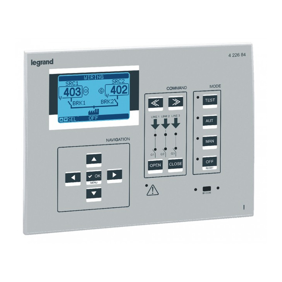
1. Introduction 1= LCD Display 4 226 84 2= Command area COMMAND MODE TEST LINE 1 LINE 2 LINE 3 3= Selection of ATS work modality NAVIGATION OPEN CLOSE RESET MENU 5= IR Port IR COM 6= Alarm LED 4= Navigation Front button functions OFF button - Selects OFF operating mode. - Page 7 The simulation cycle may be started on the command menu. Energising the euipment • 422684 has two power supplies: 100-240VAC or 12-24-48VDC. Priority is given to the AC power if both are present at the same time. • The euipment is normally set to the OFF mode when it is switched on. Modify parameter P01.03 in the M01 Utility menu if the operating mode selected before switch-off must be maintained.
-
Page 8: Operating Modes
2. Operating modes Password entry Synoptic Voltages Control menu Currents Setup parameters Powers Information page Alarms Input/output state Control thresholds Battery state Events log Statistics Password protected access • The password is used to enable or block access to the setting menu and the command menu. •... - Page 9 Three-Sources Management System (T.S.M.S.) Navigating the display pages • The ▲ and ▼buttons allow the measurement display pages to be scrolled one at a time. The current page is shown on the title bar. • Some measurements may not be viewed according to the programming and connection of the euipment (e.g. the re- spective page will not appear if no fuel level sensor is set).
- Page 10 2. Operating modes 2.5.1 Display pages table PAGES EXEMPLE PAGES EXEMPLE Phase Phase to phase voltage voltage Alarm Control status thresholds Statistics Events list Inputs and Expansion outputs modules status Outputs Inputs System Date / Time info Automatic test...
- Page 11 (T.S.M.S.) Expandability • With its expansion bus, the ref. 422684 be expanded with the additional modules of the EXP…. series. • Up to three EXP… modules can be installed at the same time. • The EXP… modules supported by the ref. 422684 are divided into the following categories:...
- Page 12 For example, by defining a LIMx threshold as counting source it will be possible to count how many times a measurement exceeds a given value. • The following table shows all the internal variables managed by the ref. 422684 with their range (number of variables per type).
- Page 13 • Example: a relay using the control software can be freely activated and deactivated by using a remote variable (REMx) as source of an output (OUTx). This would allow to use ref. 422684 422684 output relays to control loads, e.g. lighting or other.
-
Page 14: Automatic Test
2.11 PLC logic (PLCx) • Xpress can be set using a ladder program for creating a PLC internal logic inside the ref. 422684 422684, so as to be able to freely create any function necessary for genset accessory applications. • In the program logic, all the variables managed internally by the ref. 422684 can be entered, such as inputs (INPx), th- reshold limits (LIMx), remote variables (REMx), controller states (RALx) etc. -
Page 15: Keypad Lock
2.17 Parameter setting from smartphone or tablet with WIFI DONGLE • It is possible to connect to the ref. 422684 by means of the app ACU configurator, available for tablet and Android or iOS smartphones, and the CX02 accessory. • The app can be used to view alarms, send controls, read measurements, set parameters, download events and sent... -
Page 16: Parameter Settings (Setup) From Front Panel
2. Operating modes 2.18 Parameter settings (setup) from front panel • To access the parameter programming menu (setup): - Set the board to OFF mode - On the normal measurement display, press ▲ and ▼ at the same time to recall the main menu - Select the icon . -
Page 17: Parameter Table
Three-Sources Management System (T.S.M.S.) • Select the sub-menu and press ✓ to view the parameters. • All parameters are shown with code, description, current value. Set-up: parameter selection 2.19 Parameter table M01 - UTILITIES UNIT DEFAULT RANGE Language English English P01.01➊... - Page 18 2. Operating modes M02 - GENERAL UNIT DEFAULT RANGE P02.01 System layout E 3S - 0T E : 3S – 0T F: 3S – 1T – PL G: 3S – 1T – AI H: 3S – 1T – PS I: 3S -1T - RI J: 3S –...
- Page 19 Three-Sources Management System (T.S.M.S.) M02 - GENERAL UNIT DEFAULT RANGE P02.28 Description of tie breaker 1 (char*4) P02.29 Description of tie breaker 2 (char*4) P02.30 Tie breaker closing delay 0.1 … 60.0 P02.31 Pre-transfer time load 1 OFF / 1-1000 P02.32 Post-transfer time load 1 OFF / 1-1000...
- Page 20 P04.03 - MIN battery voltage alarm tripping threshold. P04.04 - Tripping delay between MIN and MAX battery alarms. P04.05-P04.06-P04.07-P04.08 - Serial communication enabling between 422684 and any BCG…RS series communica- ting battery chargers. It allows to read the voltages, charging currents and alarms concerning the corresponding battery charger and to view information on the dedicated video page.
- Page 21 Three-Sources Management System (T.S.M.S.) M05 - ACOUSTIC ALARMS UNIT DEFAULT RANGE P05.01 Siren sound mode on alarm Timed Keypad Timed Repeated P05.02 Sound activation time on alarm OFF/1-600 P05.03 Sound activation time before starting OFF / 1-60 P05.04 Sound activation time on remote control start OFF / 1-60 P05.05 Sound activation time for no line S.1...
- Page 22 2. Operating modes P06.n.04 - Maximum cooling cycle time. Example: time which elapses between the load disconnection of the genset and the actual stopping of the engine. M07 - BREAKERS UNIT DEFAULT RANGE (Qn, n=1…3) P07.n.01 Breaker description (char*6) P07.n.02 0.1…1800.0 Interlock time SQ.x ➔...
- Page 23 Three-Sources Management System (T.S.M.S.) M08 - SWITCH UNIT DEFAULT RANGE P08.01 Transfer device type Pulse control breakers Pulse control Q. Continuous control Q. Contactor P08.02 Transfer strategy P08.03 Maximum load not powered time OFF / 1…3600 (alarm A09 tripping delay) P08.04 Automatic return OFF / ON...
- Page 24 2. Operating modes P08.04 - If this parameter is enabled after a transfer to an alternative line the return on the priority line does not occur automatically when it is re-established but must be controlled in manual mode. OFF = Automatic return ON = Return to manual.
- Page 25 Three-Sources Management System (T.S.M.S.) M09 - SOURCE LINE CHECK UNIT DEFAULT RANGE (SLC, n=1…3) MIN release voltage limit 70-100 P09.n.01➊ P09.n.02➊ MIN reset threshold 70-100 MIN voltage delay 0-600 P09.n.03➊ P09.n.04➊ MAX release voltage limit 100-130 / OFF MAX reset threshold 100-130 / OFF P09.n.05➊...
- Page 26 2. Operating modes P09.n.11, P09.n.12 - P09.n.11 These define the maximum imbalance threshold between the phases referred to rated voltage and P09.n.12 is the respective tripping delay. This control may be disabled by setting P09.n.11 to OFF. P09.n.13 - Maximum frequency tripping threshold; may be deactivated. P09.n.14 - Maximum frequency tripping delay.
- Page 27 Three-Sources Management System (T.S.M.S.) M11 - AUTOMATIC TEST UNIT DEFAULT RANGE Automatic TEST enable group 1 OFF / ON P11.01➊ P11.02➊ Automatic TEST enable group 2 OFF / ON Automatic TEST enable group 3 OFF / ON P11.03➊ P11.04➊ Interval between TESTS 1-60 Enable TEST for Monday OFF / ON...
- Page 28 P14.03 - This defines in which operating modes to activate the output programmed with the Operating mode function. For example, if this parameter is programmed on M-O, the Operating mode output will be activated when the ref. 422684 is in MAN or OFF mode.
- Page 29 Note: This menu is divided into 16 sections for limit thresholds LIM1..16. P15.n.01 - This defines which measurements supplied by the ref. 422684 to apply the limit threshold. P15.n.02 - If the reference measurement is an electric measurement, this defines whether it refers to the mains or the genset.
- Page 30 Note: This menu is divided into 8 sections for counters CNT1..8. P16.n.01 - Signal which causes the counter increments (on ramp up). It may be energised by the ref. 422684 (ON), the exceeding of a threshold (LIMx), the activation of an external input (INPx), a logical condition (PLCx) etc.
- Page 31 Three-Sources Management System (T.S.M.S.) M17 - TIMER UNIT DEFAULT RANGE (TIMn, n = 1…8) P17.n.01 Timer source INPx OUTx LIMx REMx PLCx RALx P17.n.02 Channel no. (x) 1-99 P17.n.03 Delay 0.0 – 6000.0 Note: This menu is divided into 8 sections for the timers TIM1..8. P17.n.01 - Source variable which controls the starting and resetting of the concerned timer.
-
Page 32: Alarm Properties
• Enabled alarm – General alarm enable. If not enabled, it is as if it does not exist. • AUT only – The alarm may only be generated when ref. 422684 ATS is in automatic mode. • Retaining alarm – This remains stored even if its cause was removed. -
Page 33: Alarms Table
Three-Sources Management System (T.S.M.S.) 2.22 Alarms table The following table shows the alarm codes, together with a description and the default properties of each one. CODE DESCRIPTION ● ● ● ● Battery voltage too low ● ● ● ● Battery voltage too high ●... -
Page 34: Description Of The Alarms
Maintenance operations Q2 As above, referred to Q2. Maintenance operations Q3 As above, referred to Q3. Auxiliary voltage breaker The device which manages the draw of auxiliary voltage from the available alarm line (Legrand DPS Ref. 422686) indicates a fault/malfunctioning. continue... -
Page 35: Programmable Input Functions Table
Auxiliary contact which informs the ref. 422684 of the open/closed Line 1 breaker closed (Feedback Q1) state of breaker Q1. If this signal is not connected, ref. 422684 considers the state of the breaker corresponding to the control output state. Line 2 breaker closed As above, referred to Q2. - Page 36 2. Operating modes FUNCTION DESCRIPTION Line 2 in breaker tripped (Trip Q2) As above, referred to Q2. Line 3 in breaker tripped (Trip Q3) As above, referred to Q3. Line 1 breaker withdrawn The input generates the breaker QQ1 withdrawn alarm when the (Withdrawn Q1) contact opens.
- Page 37 Auxiliary contact which informs the ref. 422684 of the open/closed Tie breaker QC1 feedback state of tie breaker QC1. If this signal is not connected, ref. 422684 considers the state of the tie breaker corresponding to the control output state.
- Page 38 2. Operating modes FUNCTION DESCRIPTION Q.C1 tie breaker protection trip As above, referred to Q.C1. Q.C2 tie breaker protection trip As above, referred to Q.C2. NPL breaker withdrawn The input generates NPL breaker withdrawn alarm when the contact opens. Q.C1 tie breaker withdrawn As above, referred to Q.C1.
- Page 39 As above, referred to S.Q3. Siren Powers the acoustic warning siren. Operative mode Output energised when the ref. 422684 is in one of the modes set with parameter P14.03. OFF mode Energised when ref. 422684 is in OFF mode. Energised when ref. 422684 is in MANUAL mode.
- Page 40 2. Operating modes FUNCTION DESCRIPTION Load on Line S.Q2 Breaker Q2 closed. Load on Line S.Q3 Breaker Q3 closed. Alarms A01-Axx Output energised when alarm Axx is active (xx=1…alarm number). Alarms UA1..Uax Output energised when alarm Uax is active (x=1…8). Timer TIM(x) Output controlled by state of timer variable TIM(x).
- Page 41 2.28 System layout The possible system layouts supported by the ref. 422684 are listed below. The following information is provided for each one: • The code used for selecting the layout type in the parameter setting P02.01 of the GENERAL menu (example: B: 2S-1T-PL) •...
-
Page 42: Installation
2.30 Installation • 422684 is designed to be flat panel mounted. Frontal protection of IP65 is guaranteed with correct assembly and optio- nal sealing. • Insert the system in the panel hole making sure that the seal, if present, is correctly positioned between the panel and instrument frame. -
Page 43: Wiring Diagrams
Three-Sources Management System (T.S.M.S.) 3. Wiring diagrams Terminal arrangement 22 23 24 25 LINE3 RS485 CURRENT OUT 7 53 A1 SUPPLY 54 A2 BATTERY 40 41 42 43 44 45 46 47 Mechanical dimensions and panel cutout... -
Page 44: Technical Characteristics
4. Technical characteristics TECHNICAL CHARACTERISTICS AC power: terminals 53, 54 Us rated voltage 100 – 240V~ Operating limits 90 – 264V~ Frequency 45 – 66Hz 100V~ 12,5VA, 7W Drawn/dissipated power 240V~ 16,5VA, 7,3W Micro-interruption immunity time ≤40ms (110V~ ) (without expansion modules) ≤200ms (220V~ ) Micro-interruption immunity time ≤20ms (110V~ ) - Page 45 Three-Sources Management System (T.S.M.S.) TECHNICAL CHARACTERISTICS Outputs OUT2, OUT4 and OUT6: terminals 56-57, 59-60 and 62-63 Contact type 3 x 1 NO AC1 – 8A 250V~ Rating AC15 -1,5A 250V~ Maximum usage voltage 300V~ Electrical/mechanical time 1x10⁷ / 1x10 operations Maximum current on terminals 55, 59 and 62 Outputs OUT7, OUT9, OUT10 and OUT 11: terminals 19-21, 30-32, 33-35 and 36-38 Contact type...
- Page 46 4. Technical characteristics TECHNICAL CHARACTERISTICS Ambient operating conditions Temperature of use -30 - +70°C Storage temperature -30 - +80°C Relative humidity < 80% (IEC/EN 60068-2-78) Maximum environmental pollution Degree 2 Overvoltage category Measurement category Climate seuence Z/ABDM (IEC/EN 60068-2-61) Shock resistance 15g (IEC/EN 60068-2-27) Vibration resistance 0.7g (IEC/EN 60068-2-6)
- Page 47 Three-Sources Management System (T.S.M.S.)
- Page 48 Pro and Consumer Service BP 30076 - 87002 LIMOGES CEDEX FRANCE www.legrand.com Installer stamp Legrand reserves at any time the right to modify the contents of this booklet and to communicate, in any form and modality, the changes brought to the same.
Need help?
Do you have a question about the 422684 and is the answer not in the manual?
Questions and answers