Advertisement
Quick Links
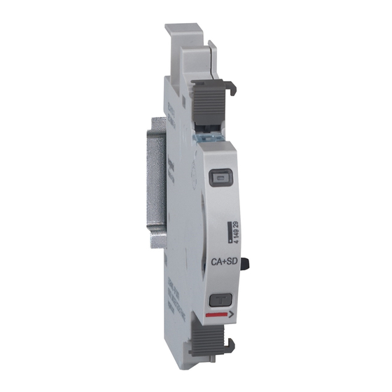
EMS CX
- Signalling Auxiliary Contact
3
(CA + SD)
1. DESCRIPTION - USE
. Module dedicated to Energy Management System (EMS CX
. Auxiliary and Fault signalling electronic module (CA+SD): indicates
contacts position (open or closed) and fault tripping of Legrand
modular associated device (MCB, RCBO, RCCB or Remote trip
head IS).
Symbol:
2. RANGE
. Cat. n° 4 149 29: electronic auxiliary contact (CA) + fault signalling
(SD).
Width:
. ½ module. 8,8 mm width.
3. OVERALL DIMENSIONS
Technical data sheet: F02334EN/02
LEGRAND - BP30076
87045 LIMOGES CEDEX FRANCE
Telephone: +33 5 55 06 87 87 - Fax: +33 5 55 06 88 88
Cat. N°: 4 149 29
4. PREPARATION -CONNECTION
) use.
Fixing:
3
. On symmetric rail EN/IEC 60715 or DIN 35 rail
Operating positions:
. Vertical,
Power Supply:
. Mandatory in 12 VDC via the specific Power supply module Cat n°4
149 45
. Two ways:
via specific communication patch cords (cat. nos 4 149 07/08/09) to
connect at the downstream through dedicated ports
via specific communication rails (cat. nos 4 149 01/02/03) to
connect at the rear through dedicated connectors.
Updated: 07/11/2018
Contents
1. Description - Use ............................................. 1
2. Range............................................................... 1
3. Overall dimensions .......................................... 1
4. Preparation - Connection ................................. 1
5. General characteristics .................................... 4
6. System architectures ....................................... 8
6.1 Stand-alone ........................................................ 8
6.1.1 with local addressing ..................................... 8
6.1.2 with remote addressing ................................. 8
6.2 Supervised ....................................................... 10
6.2.1 with local addressing ................................... 10
6.2.2 with remote addressing ............................... 12
7. Compliance and approvals ............................ 14
Horizontal,
Upside down,
Pages
On the side
Created: 20/07/2016
1 / 14
Advertisement

Related Manuals for LEGRAND 4 149 29


Summary of Contents for LEGRAND 4 149 29
-
Page 1: Table Of Contents
149 45 . Two ways: 2. RANGE via specific communication patch cords (cat. nos 4 149 07/08/09) to . Cat. n° 4 149 29: electronic auxiliary contact (CA) + fault signalling connect at the downstream through dedicated ports (SD). Width: . -
Page 2: Preparation -Connection
. If signalling and control auxiliaries are associated on the same circuit breaker, the control auxiliary must be placed to the left of the signal auxiliary (ref. 4 062 5x / 6x or 4 149 29). List of allowed associations (Particular rules): . - Page 3 EMS CX - Signalling Auxiliary Contact Cat. N°: 4 149 29 (CA + SD) 4. PREPARATION –CONNECTION 4. PREPARATION –CONNECTION (continued) (continued) Data connection (EMS CX modules inter-connection): Data connection (EMS CX modules inter-connection) (continued) . Via specific communication patch cords (cat. nos 4 149 07/08/09) .
-
Page 4: General Characteristics
EMS CX - Signalling Auxiliary Contact Cat. N°: 4 149 29 (CA + SD) 4. PREPARATION –CONNECTION 5. GENERAL CHARACTERISTICS (continued) Data connection (EMS CX modules inter-connection) Front face marking: . By permanent ink pad printing (red line) and laser marking (continued) . - Page 5 EMS CX - Signalling Auxiliary Contact Cat. N°: 4 149 29 (CA + SD) 5. GENERAL CHARACTERISTICS (continued) Test button: . It allows to check the correct association between the module and the associated device. Functions button: . Front face button as several functions: .
- Page 6 EMS CX - Signalling Auxiliary Contact Cat. N°: 4 149 29 (CA + SD) 5. GENERAL CHARACTERISTICS (continued) Link Functionality: . This function allows you to link two EMS CX modules to create automatic actions that, once programmed, can run independently without a connection to a manager is needed.
- Page 7 EMS CX - Signalling Auxiliary Contact Cat. N°: 4 149 29 (CA + SD) 5. GENERAL CHARACTERISTICS (continued) Insulation voltage: . Ui = 400 V Pollution degree: . 2 according to IEC/EN 60898-1. Overvoltage category: . III Dielectric strength: . 2500 V Tripping force: .
-
Page 8: System Architectures
. It is possible to assign to several devices the same address with the purpose of grouping different functions, because they are related to the same electrical circuit. For example, it is possible to assign the same address to a signalling auxiliary module (cat. no 4 149 29), a universal control module (cat. -
Page 9: With Remote Addressing
EMS CX - Signalling Auxiliary Contact Cat. N°: 4 149 29 (CA + SD) 6. SYSTEM ARCHITECTURES 6.1 Stand-alone system (continued) 6.1.2 Stand-alone system with remote addressing (through a computer) Remote addressing advantages: Whole configuration (addresses and functions) can be set up through the EMS Configuration software... - Page 10 It is possible to assign to several devices the same address with the purpose of grouping different functions, because they are related to the same electrical circuit. For example, it is possible to assign the same address to a signalling auxiliary module (cat. no 4 149 29), a universal control module (cat.
- Page 11 It is possible to assign to several devices the same address with the purpose of grouping different functions, because they are related to the same electrical circuit. For example, it is possible to assign the same address to a signalling auxiliary module (cat. no 4 149 29), a universal control module (cat.
- Page 12 EMS CX - Signalling Auxiliary Contact Cat. N°: 4 149 29 (CA + SD) 6. SYSTEM ARCHITECTURES (continued) 6.2 Supervised system (Computer Supervisory System) (continued) 6.2.2 Supervised system with remote addressing (through a computer) Remote addressing advantages: Whole of configuration (addresses and functions) can be done a remotely through the EMS Configuration software...
- Page 13 It is possible to assign to several devices the same address with the purpose of grouping different functions, because they are related to the same electrical circuit. For example, it is possible to assign the same address to a signalling auxiliary module (cat. no 4 149 29), a universal control module (cat.
- Page 14 EMS CX - Signalling Auxiliary Contact Cat. N°: 4 149 29 (CA + SD) 7. COMPLIANCE AND APPROVALS Compliance to standards: . Compliance with Directive on electromagnetic compatibility (EMC) n° 2014/30/EU . Compliance with low voltage directive n° 2014/35/EU. . Electromagnetic Compatibility:...
Need help?
Do you have a question about the 4 149 29 and is the answer not in the manual?
Questions and answers