
Related Manuals for LEGRAND CX3 EMS


Summary of Contents for LEGRAND CX3 EMS
- Page 1 CX³ EMS ENERGY MANAGEMENT SYSTEM THE GLOBAL SPECIALIST IN ELECTRICAL AND DIGITAL BUILDING INFRASTRUCTURE...
- Page 2 Legrand offers complete solutions to meet energy efficiency needs. This technical guide provides all the essential information you need to know about in order to understand how to choose them, their characteristics, installation and configuration rules, etc … This document can be downloaded from the online catalog...
-
Page 3: Table Of Contents
CX³ EMS CONFIGURATION SOFTWARE . . . . . . . . . . . . . . . . . . . . . . . 74 CX³ EMS E TECHNICAL GUIDE nErgy anagEMEnt yStEM WWW.LEGRAND.COM... -
Page 4: Safety Instructions
Voltage / Current / Temperature values other than those specified in the Documentation. Legrand declines all responsibility for any modification or repair of the equipment making up the enclosure that is not authorized by ■... - Page 5 However, it is always the customer’s responsibility to verify and validate that Legrand products are suitable for its installation and use. The customer must ensure proper installation, maintenance and operation of the equipment to avoid any risk of injury to personnel or damage to property in the event of product failure, especially for applications that require a very high level of safety (e.g., those...
- Page 6 complete, compact and multifunctional MEASUREMENT SIGNALLING...
- Page 7 All the modules in the CX EMS supervision system have compact dimensions, in order to minimise the space taken up in the electrical switchboard . CONTROL SIGNALLING & COMMUNICATION PROGRAMMING CONTROL AND DISPLAY CX³ EMS E TECHNICAL GUIDE nErgy anagEMEnt yStEM WWW.LEGRAND.COM...
- Page 8 CX³ EMS MEASUREMENT MODULES Product specifications Measurement modules are integrated in the EMS CX³ system for monitoring energy in electrical panels. Offering the same performance as conventional measurement control units, these record the electricity consumed by a single-phase or three-phase circuit and measure the electrical values (current, voltage, power, frequency, harmonics, etc). There are 2 measurement module families: ■...
- Page 9 ■ Supply voltage: ■ Connection with CT: No display on the module itself, however 12 VDC via CX3 EMS power supply Supplied for Cat.Nos 4 149 18 / 19 / 20 / data can be displayed locally (on mini- module Cat.No: 4 149 45.
- Page 10 PRODUCT SELECTION The measurement module should be chosen according to the supply (single-phase or three phase), its maximum current and,from the current transformer type. 4 149 18 4 149 19 4 149 20 4 149 21 Supply type Single-phase Three-phase Number of modules Direct (max.current) Up to 63 A...
- Page 11 Up to 3200 A Up to 6300 A 5 A at the secondary Up to 15th order Up to 15th order Up to 15th order Up to 15th order Up to 15th order CX³ EMS E TECHNICAL GUIDE nErgy anagEMEnt yStEM WWW.LEGRAND.COM...
- Page 12 VIEWING DATA To minimise the dimensions, measurement modules do not have a data display. Nonetheless various display modes are possible: Locally, int the enclosure, on mini-configurator, Remotely, on a PC, tablet or smartphone screen. The CX³ EMS / Cat.No 4 149 36 : RS485 / IP interfaces Cat.No 4 149 40 and 0 046 89 must be used to access devices such as the touch screen, the Energy Management software Cat.No 4 149 38/39 and the Energy Web Server...
- Page 13 F: 0,5 A gG m² ø 9,3 F: 0,5 A gG WWW.LEGRAND.COM .La longueur du câble entre le/les tore(s) Rogowski (cf § Côtes .La longueur du câble entre le/les tore(s) Rogowski (cf § Côtes d’encombrement) laisse la possibilité de mettre le module de...
- Page 14 WIRING (CONTINUED) ■ 63 A 3 x Single: ■ 63 A Three: Cat.No 4 149 18 Cat.No 4 149 20 ■ 63 A 3 x Single: ■ 125 A Three: Cat.No 4 149 19 Cat.No 4 149 21...
- Page 15 être Mise à jour le : 07/11/2016 Créée le : 21/10/2016 enlevé. 2 / 16 2 / 16 Mise à jour le : 07/11/2016 Créée le : 21/10/2016 2 / 16 CX³ EMS E TECHNICAL GUIDE nErgy anagEMEnt yStEM WWW.LEGRAND.COM...
- Page 16 WIRING (CONTINUED) ■ 630 A, 1600 A, 3200 A et 6300 A: Cat.No 4 149 25 Cat.No 4 149 22 Cat.No 4 149 24 Cat.No 4 149 27 Measure with open flexible Rogowski coils. High performance: measurement modules: up to 6300 A. The range of CX measurement modules, now allows to measure high currents 630 A, 1600 A, 3200 A and 6300 A.
- Page 17 WIRING (CONTINUED) Lateral rotating clip for easy integration of the support in any position. CX³ EMS E TECHNICAL GUIDE nErgy anagEMEnt yStEM WWW.LEGRAND.COM...
- Page 18 WIRING (CONTINUED) ■ Voltage measurement: ■ CX³ EMS bus: The voltage is measured in the same way There are 2 possible solutions for connection to the bus: as on all measurement module catalogue numbers. At the back of the At the bottom of modules via the modules via communication...
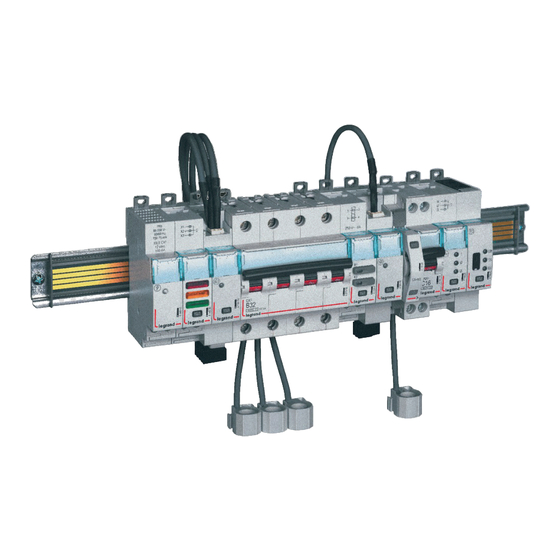
- Page 19 Therefore, the modules can integrate HX³ optimised distribution system; making it possible to have a combination of functions in the same DIN rail. The energy management modules are then as close as possible to the protection modules. OPTIMISED DISTRIBUTION POSSIBLE CX³ EMS E TECHNICAL GUIDE nErgy anagEMEnt yStEM WWW.LEGRAND.COM...
- Page 20 SETTING PARAMETERS The parameters of the measurement module - Three-phase measurement - High current measurement module can be set as follows: module Cat.No 4 149 20: Cat.No 4 149 23: -Remotely: via the CX³ EMS Like single-phase measurement Like the previous measurement modules, it configuration software.
- Page 21 CX³ EMS devices and are described in the product technical data sheets. Local setting using the selector takes priority over software Setting parameters. In the event of malfuntion, check that the selector is definitely on zero. CX³ EMS E TECHNICAL GUIDE nErgy anagEMEnt yStEM WWW.LEGRAND.COM...
-
Page 22: Cx³ Ems Pulse Concentrator
CX³ EMS PULSE CONCENTRATOR Product specifications Pulse concentrator module Cat.No 4 149 26 is integrated in the CX³ EMS system for monitoring energy in electrical panels. It collects pulses emitted by electricity, gas, water, oil meters, etc and transmits this information over the CX³... - Page 23 RS485 / IP interfaces should be used to access devices such as the touch screen Cat.No. 0 261 56, the Energy Management Software Cat.No. 4 149 38/39 and the Energy Web Servers Cat.No. 4 149 47/48/49. CX³ EMS E TECHNICAL GUIDE nErgy anagEMEnt yStEM WWW.LEGRAND.COM...
- Page 24 EMS CX – Module Concentrateur Référence(s) : 4 149 26 d’impulsions (suite) (suite) 4. MISE EN SITUATION - RACCORDEMENT 4. MISE EN SITUATION - RACCORDEMENT Bornes: Transmission des données EMS CX (connexion des modules) : . profondeur : 8 mm. .Par cordons communicants (réfs.4 149 07/08/09) .
- Page 25 Local setting using the selector takes priority over software Setting parameters. In the event of malfunction, check that the selector is definitely on zero. Setting parameters is identical and easily done using either method. CX³ EMS E TECHNICAL GUIDE nErgy anagEMEnt yStEM WWW.LEGRAND.COM...
-
Page 26: Cx³ Ems Universal Signalling Module
CX³ EMS UNIVERSAL SIGNALLING MODULE Product specifications Universal signalling module Cat.No 4 149 30 is integrated in the CX³ EMS system for monitoring energy in electrical panels. Information such as “on/off/fault”, “plugged-in/drawn-out”, etc are signalled by 3 LEDs directly on the module and sent remotely over the CX³... - Page 27 Ready to load function 1 2 3 4 Spring not loaded Details and examples can be found in «CX³ EMS Configuration Software/Product Data Sheet» on page 76. Microswitch on OFF Microswitch on ON CX³ EMS E TECHNICAL GUIDE nErgy anagEMEnt yStEM WWW.LEGRAND.COM...
- Page 28 VIEWING DATA The universal signalling module is used to transfer information fed back over the CX³ EMS bus to the IP computer network, passing via the RS485 Modbus network. Various display modes are therefore possible: Locally, enclosure, mini-configurator Remotely, on a PC, a tablet, a smarphone. The CX³ EMS /RS485/ Cat.No 4 149 36: IP interfaces should be used in order to access devices such as the touch screen Cat.
- Page 29 The specifications for connection to the CX³ EMS bus are common to all CX³ examples module EMS devices and are described in the product technical data sheets. technical data sheet 4 149 30. RAIL CONNECTION CABLE CONNECTION CX³ EMS E TECHNICAL GUIDE nErgy anagEMEnt yStEM WWW.LEGRAND.COM...
- Page 30 WIRING (CONTINUED) ■ Integration in optimised distribution system: The upper side terminals of the universal signalling module Cat.No 4 149 30 have been designed to allow single-phase and three- phase supply busbars to pass freely. Therefore, the module can inteegrate HX³ optimised distribution systems. This allows to have a combination of functions in the same DIN rail.
- Page 31 Details and examples can be found in the section «CX³ EMS configuration software/Product data sheet» on page 76. CX³ EMS E TECHNICAL GUIDE nErgy anagEMEnt yStEM WWW.LEGRAND.COM...
- Page 32 SETTING PARAMETERS (CONTINUED) ADDRESSING Addressing can be done: ■ «SLAVE» function: ■ Locally on the product Some configurations are available in SLAVE mode (slave = - addressing from 1 to 9 using a selector. duplicate function). ■ Via software This SLAVE mode is a solution for transferring information over –...
- Page 33 CX³ EMS E TECHNICAL GUIDE nErgy anagEMEnt yStEM WWW.LEGRAND.COM...
- Page 34 “FS” on the associated modular product. This information is sent remotely over the CX³ EMS bus. It is installed on the left-hand side of Legrand modular circuit breakers, RCBOs, RCDs, isolating switches with remote trip option. CHARACTERISTICS ■...
- Page 35 EMS CX³ bus to the IP computer network, passing via the RS485 Modbus network. Various display modes are therefore possible: - Locally, enclosure, mini-configurator Cat.No 4 149 36: CX³ EMS E TECHNICAL GUIDE nErgy anagEMEnt yStEM WWW.LEGRAND.COM...
- Page 36 MOUNTING The AC + FS signalling auxiliary module is installed on the left-hand side of Legrand modular circuit breakers, RCBOs, RCDs, isolating switches with remote trip option. Be careful to follow certain installation rules described in the product manuals and technical data sheets, available online.
- Page 37 Cat. Nos 4 149 07/08/09 The specifications for connection to the CX³ EMS bus are common to all CX³ EMS devices and are described in the product technical data sheets. RAIL CONNECTION CABLE CONNECTION CX³ EMS E TECHNICAL GUIDE nErgy anagEMEnt yStEM WWW.LEGRAND.COM...
- Page 38 SETTING PARAMETERS ADDRESSING Does not need any additional settings. Addressing can be done: ■ Locally on the product DATA TRANSFER - addressing from 1 to 9 using a selector. The AC + FS module transfers information directly over the EMS ■...
- Page 39 CX³ EMS E TECHNICAL GUIDE nErgy anagEMEnt yStEM WWW.LEGRAND.COM...
-
Page 40: Cx³ Ems Universal Control Module
CX³ EMS UNIVERSAL CONTROL MODULE Product specifications Universal control module Cat. No 4 149 32 is integrated in the EMS CX³ system for monitoring energy in electrical panels. It can be used to control various loads such as relays, contactors, as well as motorised controls for MCBs and MCCBs, regardless of brand. - Page 41 Les micro-switch du modul Bistable (à accrochage) Contact Normalement Ouvert (NO) obligatoirement positionnés Contact Normalement Ouvert (NO) obligatoirement positionné WWW.LEGRAND.COM . Câblage : Bistable (à accrochage) Contact Normalement Fermé Contact Normalement Ouvert (NO) Bistable (à accrochage) Contact Normalement Ouvert (NO) (NC) Bistable (à...
- Page 42 VIEWING DATA The universal control module is used to control various loads remotely via the EMS CX³ bus to the IP computer network, passing via the Modbus RS485 network. Various control modes are therefore possible: Locally, in the enclosure, on mini-configurator Cat.No 4 149 36: Remotely, on a PC, a tablet, a smarphone.
- Page 43 RAIL CONNECTION CABLE CONNECTION examples module technical data sheet 4 149 32, available online. Fiche technique : F02333FR/01 Mise à jour le : - Créée le : 21/10/2016 2 / 16 CX³ EMS E TECHNICAL GUIDE nErgy anagEMEnt yStEM WWW.LEGRAND.COM...
- Page 44 WIRING (CONTNUED) ■ Integration in optimised distribution system: The upper side terminals of the universal control module Cat.No 4 419 32 have been designed to allow single-phase and three- phase supply busbars to pass freely. Therefore, the module can integrate HX³ optimised distribution systems. This allows to have a combination of functions in the same enclosure.
- Page 45 76. . Câblage : guide to find out all the options, Contact Normalement Fermé (NC) Bistable (à accrochage) available online. Contacts liés Commande motorisée CX³ EMS E TECHNICAL GUIDE nErgy anagEMEnt yStEM WWW.LEGRAND.COM...
- Page 46 DATA TRANSFER ADDRESSING The universal control module transfers information directly over Addressing can be done: the EMS CX³ bus and can be used to transfer data to an operating ■ Locally on the product system. - addressing from 1 to 9 using a selector. As seen on page 42 («Viewing data»), information is available on the mini-configurator Cat.No 4 149 36, the touch screen ■...
- Page 47 CX³ EMS E TECHNICAL GUIDE nErgy anagEMEnt yStEM WWW.LEGRAND.COM...
- Page 48 It can be used to remotely control and view the status of 1 and 2 modules contactors up to 25 A, and also of Legrand pulse operated latching relays. Control can be done locally or remotely over the EMS CX³ bus.
- Page 49 1 2 3 4 1 module Peak hours/Off-peak hours contactor 4 125 02 2 modules Only for the state reporting 1 2 3 4 2 modules Microswitch on OFF Microswitch on ON CX³ EMS E TECHNICAL GUIDE nErgy anagEMEnt yStEM WWW.LEGRAND.COM...
- Page 50 MOUNTING: No tool is needed for mounting. CX³ EMS control and state reporting module is mounted on the left-hand side of the CX³ products listed previously. This must be done when the CX³ product is in the rest position. Be careful to follow the installation rules described in the product manuals and technical data sheet.
- Page 51 Cat.No 4 149 38/39 and the Energy Web Servers Cat.No 4 149 47/48/49. For example: The pulse operated latching relay status appears on mini-configurator screen and remote control is possible. CX³ EMS E TECHNICAL GUIDE nErgy anagEMEnt yStEM WWW.LEGRAND.COM...
- Page 52 WIRING ■ Control: ■ CX³ EMS bus: The pulse operated latching relay or the There are 2 possible solutions for connection to the bus: contactors are controlled via the CX³ EMS bus; simply connect the phase to the At the back of the terminal as shown below.
- Page 53 Therefore the module can integrate HX³ optimised distribution systems. This allows to have a combination of functions in the same enclosure. The control and state reporting module is then as close as possible to the protection modules. OPTIMISED DISTRIBUTION POSSIBLE CX³ EMS E TECHNICAL GUIDE nErgy anagEMEnt yStEM WWW.LEGRAND.COM...
- Page 54 Assemblage: Schéma de câblage : . Sur le côté gauche des télérupteurs et contacteurs modulaires Legrand 1 et 2 modules de large jusqu’à 25 A . Pas d’outils necessaries. Clipser via l’embout en plastique sur le produit associé. . Assemblage avec le produit associé en position off .
- Page 55 CX³ EMS products and are detailed in the product data sheets. Local setting using the selector takes priority over software setting. In the event of malfunction, check that the selector is definitely on zero. CX³ EMS E TECHNICAL GUIDE nErgy anagEMEnt yStEM WWW.LEGRAND.COM...
-
Page 56: Cx³ Ems Power Supply Module
CX³ EMS POWER SUPPLY MODULE Product specifications Power supply module Cat. No 4 149 45 is part of the CX³ EMS modular system for monitoring energy in electrical panels. Only this power supply dedicated to the CX³ EMS system can be used. This module supplies power by means of the communication rail and/or cables. - Page 57 (supplied with every power supply module). If there are a more than one of power supply modules in the same system, only one module should be earthed. CX³ EMS E TECHNICAL GUIDE nErgy anagEMEnt yStEM WWW.LEGRAND.COM...
- Page 58 PRODUCT SELECTION (CONTINUED) The white cable provided with the power supply module is 250 mm One power supply module can provide up to 500 mA, so long. If a longer cable is needed, an extension can be created using “conventional” (black) CX³ EMS cables and extension connectors. consumption must be calculated Maximum length of assembly: 3 m.
-
Page 59: Cx³ Ems/Rs485 Interface
The CX³ EMS bus connection specifications are common to all CX³ EMS products and are detailed in the product data sheets. To protect the power supply module, refer to the information in the product technical data sheet. CX³ EMS E TECHNICAL GUIDE nErgy anagEMEnt yStEM WWW.LEGRAND.COM... - Page 60 CX³ EMS ACCESSORIES & CONNECTIONS Product specifications Data can be connected via the CX³ EMS bus with the help of communication rails and/or cables. Communication rail Accessories such as extension connectors and protective covers for rails are available, making the CX³ EMS communication system easy to use.
- Page 61 1 plastic protective cover for rail - 630 mm long 3 rail lengths are included in the catalogue, however it is possible to obtain different lengths by selecting the bespoke version. Please discuss this with your Legrand contact (check the back cover).
- Page 62 MOUNTING ■ CX³ EMS communication rail: The communication rail clips onto 2 DIN Clipping the communication rail onto a 7.5 The communication rail is available in 3 lengths (18, 24, 36 modules) so it can be rail models: 7.5 or 15 mm thick. mm thick DIN rail.
- Page 63 A visible rail which is not protected against direct contact can be responsible for a short-circuit on the CX³ EMS bus. The maximum length of a cable or “cables + connectors” must be less than 3 m. CX³ EMS E TECHNICAL GUIDE nErgy anagEMEnt yStEM WWW.LEGRAND.COM...
- Page 64 WIRING There are 2 ways to connect CX³ EMS - Via cables which connect to the bottom modules: of each module. - Via the communication rail. To do this, Each CX³ EMS module has 2 bus you need to remove the plastic protection connectors.
- Page 65 CX³ EMS E TECHNICAL GUIDE nErgy anagEMEnt yStEM WWW.LEGRAND.COM...
- Page 66 CX³ EMS / RS485 INTERFACE Product specifications The CX³ EMS/RS485 communication in- terface Cat.No 4 149 40 is used to convert data from the CX³ EMS network to the RS485 Modbus network, so the data can be displayed and used outside the enclo- sure.
- Page 67 PC in order to configure the CX³ EMS modules. Use of the configuration software is described in the “CX³ EMS configuration software” section (see page 76). CX³ EMS E TECHNICAL GUIDE nErgy anagEMEnt yStEM WWW.LEGRAND.COM...
- Page 68 SETTING PARAMETERS ADDRESSING On the CX³ EMS/RS485 interface, the Modbus communication Addressing can be done: parameters are not necessarily set manually. ■ Locally on the product The CX³ EMS/RS485 interface automatically takes the same - addressing from 1 to 9 using the selector. Modbus settings as the RS485/IP interface connected on the same ■...
- Page 69 CX³ EMS E TECHNICAL GUIDE nErgy anagEMEnt yStEM WWW.LEGRAND.COM...
-
Page 70: Cx³ Ems Mini-Configurator
CX³ EMS MINI-CONFIGURATOR Product specifications The mini-configurator is integrated in the CX³ EMS system for monitoring energy in electrical panels. It is used locally, inside the enclosure to view all the energy monitoring data such as measurement, status and alarms, and also to control a circuit. - Page 71 Example of a circuit breaker trip: The mini-configurator is used by pressing or rotating the button on Example of a configuration error: the front of the device. CX³ EMS E TECHNICAL GUIDE nErgy anagEMEnt yStEM WWW.LEGRAND.COM...
- Page 72 MENUS OVERVIEW (CONTINUED) ■ « Function » menu ■ Examples of display Provides a list of the various modules in the Energies: Powers: installation classified by function. Voltages: State and circuit breaker control: ■ « Group » menu Provides a list of the various modules in the installation classified by group.
- Page 73 The CX³ EMS bus connection specifications are common to all CX³ EMS products and are detailed in the product data sheets. The use of the configuration software is described in the “CX³ EMS configuration software” section (see page 76). CX³ EMS E TECHNICAL GUIDE nErgy anagEMEnt yStEM WWW.LEGRAND.COM...
- Page 74 SETTING PARAMETERS ADDRESSING Various parameters can be set on the EMS CX³ mini-configurator, Addressing can be done: such as: ■ Locally on the product - Settings: date, time, password, contrast, backlighting, selector - addressing from 1 to 9 using a “virtual selector” from the address, language, definition of home page.
- Page 75 CX³ EMS E TECHNICAL GUIDE nErgy anagEMEnt yStEM WWW.LEGRAND.COM...
-
Page 76: Cx³ Ems Configuration Software
Using CX³ EMS modules in an installation as well as the configuration of the Energy Management Web Servers (Cat.No 4 149 47/48/49) allow sending emails, alert notifications, reports or events on a multiple of media: PC, smartphone, tablet ... You can find the tutorials concerning the configuration on www.legrand.com/ecatalogue. - Page 77 A complete project configuration which has already been created can be exported so it can be reused later exactly as it is, or modified for use in different project. CX³ EMS E TECHNICAL GUIDE nErgy anagEMEnt yStEM WWW.LEGRAND.COM...
- Page 78 MENUS OVEREVIEW ■ « Home » menu: The display takes the form of 4 menus providing access to various sub-menus. Access to software settings such as: version, language, communication port. Access to the system settings. Access to the project preview as it will appear for the end user.
- Page 79 Automatically displays the Access to the rest of the configuration, number of modules and groups “Edit online configuration”. composing the CX³ EMS system. Display any faults on the CX³ EMS system. CX³ EMS E TECHNICAL GUIDE nErgy anagEMEnt yStEM WWW.LEGRAND.COM...
- Page 80 ■ «Read configuration via USB » menu (continued): The configuration switches of the universal control and signaling modules, Cat.No 4 149 30 and 4 149 32, can be left in the factory configuration on 0 position. In this case, the configuration of these 2 modules is carried out via the EMS configuration software.
- Page 81 Select the configuration chosen for the module, to validate, click on «ok». CX³ EMS E TECHNICAL GUIDE nErgy anagEMEnt yStEM WWW.LEGRAND.COM...
- Page 82 ■ « Edit online configuration » menu, page « Module groups » The name of the group can be chhanged. Error detection. Direct access to the project preview as it appears to the end user. Quick identification of CX³ EMS module(s): By pressing this icon, the Access to the modules belonging relevant EMS module(s) will blink.
- Page 83 ■ Normal contact type: normally open or normally closed. ■ Type of contact activation: impulse, maintained. ■ Activation time: adjustable time delay. ■ Duration of the activation delay: adjustable delay time. ■ …. CX³ EMS E TECHNICAL GUIDE nErgy anagEMEnt yStEM WWW.LEGRAND.COM...
- Page 84 ■ « Edit online configuration » menu, page « Modules » (continued) All the measurement modules are configurable via the configuration software. Example of an advanced configuration page for a three-phase measurement module. Possible settings for this type of CX³ EMS module: ■...
- Page 85 Adjust the parameters associated with the load-shedding function. Complete setting load-shedding function using the advanced parameters of the universal control module. CX³ EMS E TECHNICAL GUIDE nErgy anagEMEnt yStEM WWW.LEGRAND.COM...
- Page 86 ■ « Link function » menu The «link» function allows you to create automatic actions by linking 2 CX³ EMS modules from 2 different groups. You just need to associate a module generating the event with a module generating the action. Below is a list of possible combinations: Modules generating the action Modules generating the event Control...
- Page 87 CX³ EMS configuration software from CX³ EMS Configuration Software, which can www.legrand.com/ecatalogue be downloaded from www.legrand.com/ecatalogue The link function is only possible since the 2nd half of 2018, an update of the modules is possible for older products. Details in the section «menu»...
- Page 88 All Linked functions are listed on this page. Add a function. Modify an existing function. Delete an existing function. The setting of the link function is detailed in the Installation Manual of the CX³ EMS configuration software downloadable from www.legrand.com/ecatalogue...
- Page 89 ■ « Link function » menu (continued) Once the linked functions are created, the relevant modules are identified by this symbol. CX³ EMS E TECHNICAL GUIDE nErgy anagEMEnt yStEM WWW.LEGRAND.COM...
- Page 90 ■ « View project » « view measurement » menu Used to have a project preview identical to the one of the end user. Display the status of each group and Example of displaying “measurement” the icons of the associated functions: data, in this case harmonics.
- Page 91 ■ ON / OFF / FLT status Access to the data to be displayed. ■ Functions: measurement view, control … ■ Connection fault ■ Connection OK ■ … CX³ EMS E TECHNICAL GUIDE nErgy anagEMEnt yStEM WWW.LEGRAND.COM...
- Page 92 The procedure for updating the modules is detailed in the CX³ EMS Configuration Software Installation Manual, which can be downloaded from www.legrand.com/ecatalogue Module updates are downloaded and saved to your PC automatically when downloading the new version of EMS configurator.
- Page 93 2nd half of 2018, an update of the modules is of CX³ EMS configuration software from possible for older products. Details in the www.legrand.com/ecatalogue section «menu/module firmware update». CX³ EMS E TECHNICAL GUIDE nErgy...
- Page 94 ■ « Errors and alarms » menu The CX³ EMS system memorise the last 20 errors and alarms which have appeared during configuration. The table indicates the date, time, group name, address and type of error or alarm.
- Page 95 Notes CX³ EMS E TECHNICAL GUIDE nErgy anagEMEnt yStEM WWW.LEGRAND.COM...
- Page 96 Notes...
- Page 97 Notes CX³ EMS E TECHNICAL GUIDE nErgy anagEMEnt yStEM WWW.LEGRAND.COM...
- Page 98 FOLLOW US ALSO ON legrand.com youtube.com/user/legrand facebook.com/Legrand twitter.com/Legrand pinterest.com/legrandgroup instagram.com/legrandnews Head office and International Department 87045 Limoges Cedex - France Tel: + 33 (0) 5 55 06 87 87 Fax: + 33 (0) 5 55 06 74 55...
Need help?
Do you have a question about the CX3 EMS and is the answer not in the manual?
Questions and answers