Table of Contents
Advertisement
Quick Links
Advertisement
Table of Contents

Related Manuals for Fibocom H330S


Summary of Contents for Fibocom H330S
- Page 1 H330S Hardware User Manual Version:V1.1.7 Date:2016.06.17 第 1 页 共 44 页...
- Page 2 H330S-A50-00 900/1800 900/2100 5.76 H330S-A30-20 900/1800 900/2100 5.76 H330S-A50-20 900/1800 900/2100 5.76 H330S-Q50-20 850/900/1800/1900 850/900/1900/2100 5.76 H330S-Q30-20 850/900/1800/1900 850/900/1900/2100 5.76 Reproduction forbidden without Fibocom Wireless Inc. written authorization - All Rights Reserved. H330S Hardware User Manual Page 2 of 44...
- Page 3 2013-07-01 Add comparison on voice SMI is updated to a output pin; update section 5.4.1; V1.0.8 2013-09-13 Update Figure5-2, Figure5-4; Reproduction forbidden without Fibocom Wireless Inc. written authorization - All Rights Reserved. H330S Hardware User Manual Page 3 of 44...
- Page 4 Update the 12C and 12S description of H330S-XXX-20 V1.1.6 2015-11-17 Update the maximum operating voltage to 4.2V V1.1.7 2016-06-17 Add the H330S-Q30-20 Reproduction forbidden without Fibocom Wireless Inc. written authorization - All Rights Reserved. H330S Hardware User Manual Page 4 of 44...
-
Page 5: Table Of Contents
5.2.2 Power on Signal..........................27 5.2.3 Power off Signal..........................28 5.2.4 Reset Signal............................. 29 5.3 Status Indicating Signal...........................30 5.3.1 LPG Signal............................30 5.3.2 SMI Signal............................30 Reproduction forbidden without Fibocom Wireless Inc. written authorization - All Rights Reserved. H330S Hardware User Manual Page 5 of 44... - Page 6 6.1 Electrical Features............................ 41 6.2 Environmental Features.......................... 41 7 RF Interface............................42 7.1 Operating Frequency Band........................42 7.1.1 Frequency Range of Main Antenna....................42 Reproduction forbidden without Fibocom Wireless Inc. written authorization - All Rights Reserved. H330S Hardware User Manual Page 6 of 44...
- Page 7 7.3.1.1 Antenna efficiency........................43 7.3.1.2 S11 or VSWR..........................43 7.3.1.3 Polarization..........................43 7.3.1.4 Radiation pattern........................43 7.3.1.5 Gain and directivity.........................43 7.3.1.6 Interference..........................44 7.3.1.7 TRP/TIS...........................44 Reproduction forbidden without Fibocom Wireless Inc. written authorization - All Rights Reserved. H330S Hardware User Manual Page 7 of 44...
-
Page 8: Foreword
1.1 Introduction The document describes the electrical characteristics, RF performance, dimensions and application environment, etc. of H330S series wireless modules. With the assistance of the document and other instructions, developers can quickly understand the performance of H330S series wireless modules and develop products. -
Page 9: Product Overview
2 Product Overview 2.1 Description H330S series modules are 3G wireless modules with high integration density, supporting GSM/GPRS/ EDGE and UMTS/HSDPA/HSUPA/HSPA+. 2.2 Specifications Specifications UMTS (WCDMA/FDD): 850/900/1900/2100 MHz or 900/2100MHz Operating Frequency Range GSM/GPRS/EDGE: 850/900/1800/1900 MHz or 900/1800MHz UMTS/HSDPA/HSUPA 3GPP release 7 HSUPA 5.76Mbps (Cat 6) - Page 10 Multi-slot class 33(5 Down; 4 Up; 6 Total) GPRS Coding Scheme CS1~4 UMTS(14.4kbps), GSM(9.6kbps) USSD Support MO / MT Text and PDU modes Reproduction forbidden without Fibocom Wireless Inc. written authorization - All Rights Reserved. H330S Hardware User Manual Page 10 of 44...
- Page 11 For the temperature is out of the normal temperature range: -30℃ ~ +75, some indexes may ① slightly deviate from the related 3GPP codes. ②:H330S-XXX-20 serials module dose not support I2C/I2S/Analog Audio and Digital Audio. Reproduction forbidden without Fibocom Wireless Inc. written authorization - All Rights Reserved. H330S Hardware User Manual...
-
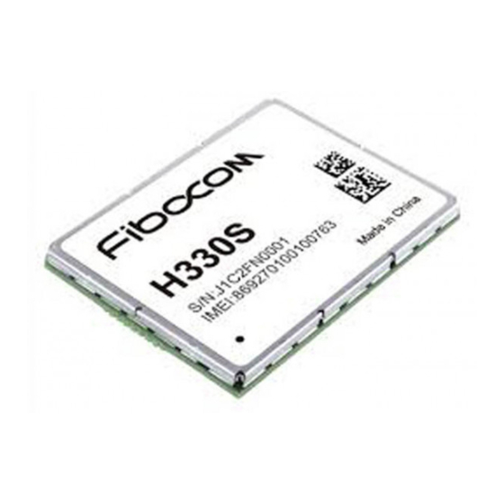
Page 12: Appearance
2.3 Appearance The product appearance of H330S series wireless module is shown as below: Top view: Figure 2- 1 Top View Bottom view: Figure 2- 2 Bottom View Reproduction forbidden without Fibocom Wireless Inc. written authorization - All Rights Reserved. -
Page 13: Structure
3.1 Dimension Diagram of Structure Figure 3- 1 Dimension Diagram of Structure 3.2 PCB Layout Design Figure 3- 2 Recommended PCB Layout (Top View) Reproduction forbidden without Fibocom Wireless Inc. written authorization - All Rights Reserved. H330S Hardware User Manual Page 13 of 44... -
Page 14: Hardware Introduction
4 Hardware Introduction 4.1 Hardware Block Diagram Figure 4- 1 Block Diagram Reproduction forbidden without Fibocom Wireless Inc. written authorization - All Rights Reserved. H330S Hardware User Manual Page 14 of 44... -
Page 15: Pin Definition
4.2 Pin Definition 4.2.1 Pin Map TOP (View) Figure 4-2 Pin Diagram Reproduction forbidden without Fibocom Wireless Inc. written authorization - All Rights Reserved. H330S Hardware User Manual Page 15 of 44... -
Page 16: Description Of Pins
4.2.2 Description of Pins The logic signal lever of H330S series is 1.8V. Pins of H330S series are described in the table below: Reset Idle Pin # Pin Name Description Value Value Power Supply VBAT VBAT Main power supply, voltage range: 3.3V ~ 4.2V. - Page 17 I2S2 serial data input USB_DP USB data signal+ USB_DM USB data signal- USB_ID — USB ID signal VUSB USB Power Input Reproduction forbidden without Fibocom Wireless Inc. written authorization - All Rights Reserved. H330S Hardware User Manual Page 17 of 44...
- Page 18 External interrupt, active low. USB HSIC HSIC USB data signal line HSIC_USB_DATA (not supported) HSIC USB pulse signal line HSIC_USB_STRB (not supported) Reproduction forbidden without Fibocom Wireless Inc. written authorization - All Rights Reserved. H330S Hardware User Manual Page 18 of 44...
- Page 19 GPIO . Used for HSIC IPC in special DSP_AUDIO_IN1 software versions CLKOUT0 Digital audio clock output Sleep Mode Indicator Status indicator Reproduction forbidden without Fibocom Wireless Inc. written authorization - All Rights Reserved. H330S Hardware User Manual Page 19 of 44...
- Page 20 Reset Idle Pin # Pin Name Description Value Value Reproduction forbidden without Fibocom Wireless Inc. written authorization - All Rights Reserved. H330S Hardware User Manual Page 20 of 44...
- Page 21 T:Tristate OD:Open Drain PP:Push-Pull Note: ③: the pin28(I2C_SDA) and pin27(I2S2_RX) of the H330S-XXX-20 series is floating, please don not use. Reproduction forbidden without Fibocom Wireless Inc. written authorization - All Rights Reserved. H330S Hardware User Manual Page 21 of 44...
-
Page 22: Hardware Interface
5 Hardware Interface 5.1 Power Interface 5.1.1 Power Supply H330S modules require 3.3V~4.2V direct current power supply, which can provide the maximum GSM emission current of 2A. Input power supply requirements: Parameter Minimum Value Recommended Value Maximum Value Unit VBAT Points for attention in design: 1. - Page 23 DCS1800 PCL PCS1900 PCL GSM850 PCL GPRS Class 33 - EGSM900 PCL GPRS-RMS 4 TX slot 1 Rx slot DCS1800 PCL Reproduction forbidden without Fibocom Wireless Inc. written authorization - All Rights Reserved. H330S Hardware User Manual Page 23 of 44...
- Page 24 1 Rx slot DCS1800 PCL PCS1900 PCL 1655 GSM850 PCL 1715 Peak current EGSM900 PCL GSM-MAX During TX slot 1050 DCS1800 PCL Reproduction forbidden without Fibocom Wireless Inc. written authorization - All Rights Reserved. H330S Hardware User Manual Page 24 of 44...
-
Page 25: Vio
VIO can be used as the reference level of the module’s digital signals. Parameter Minimum Value Recommended Value Maximum Value Unit VIO in operation 1.773 1.827 Reproduction forbidden without Fibocom Wireless Inc. written authorization - All Rights Reserved. H330S Hardware User Manual Page 25 of 44... -
Page 26: Vrtc
T= (1.8-0.5)*C/1=1.3C, unit: second. Namely, if the value of C9 is 100uF, the retaining time of RTC will be around 130s. Reproduction forbidden without Fibocom Wireless Inc. written authorization - All Rights Reserved. H330S Hardware User Manual Page 26 of 44... -
Page 27: Power On/Off And Reset Signal
5.2 Power on/off and Reset Signal 5.2.1 Pin Definition of Power on/off Control Signal H330S wireless modules provide three control signals to start up, shut down, and reset the modules. Pins definition as listed below : Pin# Pin Name Electrical Level... -
Page 28: Power Off Signal
Figure 5- 4 Timing Control The recommended design of POWER_OFF signal is as follows: Figure 5- 5 POWER_OFF Reference Design Reproduction forbidden without Fibocom Wireless Inc. written authorization - All Rights Reserved. H330S Hardware User Manual Page 28 of 44... -
Page 29: Reset Signal
5.2.4 Reset Signal H330S wireless modules support external reset function. It is feasible to reset the module back to the original state by the Reset Signal. When setting the Reset Signal low for 100ms, the module will be reset and restarted. When the user uses the Reset function, the PMU inside the module will not lose power. -
Page 30: Status Indicating Signal
SMI signal description as listed below : Modes Description Sleep Mode 2.5S High; 100ms Low,repeat this Other Mode low level Reproduction forbidden without Fibocom Wireless Inc. written authorization - All Rights Reserved. H330S Hardware User Manual Page 30 of 44... -
Page 31: Wake_Up Signal
It is only used for indicating work conditions. Keep it in the idle state in actual use. It cannot be used for other purposes. Reproduction forbidden without Fibocom Wireless Inc. written authorization - All Rights Reserved. H330S Hardware User Manual... -
Page 32: Usb Interface
— USB TEST signal(NC is recommended) H330S wireless modules support USB 2.0. Before connecting it to PC, it is necessary to install the related USB driver. After inserting the H330S wireless modules to PC, the USB interface will work with the driver and map... -
Page 33: Uart Interface
5.5 UART Interface 5.5.1 UART Interface Description H330S wireless modules provide two UART for the users; one is standard 8-line serial port, and the other 2-line serial port. The 8-line serial port UART1 supports full serial port mode with flow control function, and all the AT commands. -
Page 34: Uart Interface Application
UART2_RXD UART2 Received Data UART2_TXD UART2 Transmitted Data 5.5.2 UART Interface Application Connect UART1 of H330S wireless module (DCE) to PC, and the signal direction of (DTE) is as follows: MCU (DTE) application Signal Direction H330S module (DCE) UART1_TXD UART1_RXD... -
Page 35: Ring Indication
1s high level, and 1s low level, repeat this. New SMS 150ms pulse 5.6 USIM Interface H330S series wireless modules support USIM and high speed SIM cards. For now, they do not support 8-line intelligent USIM. 5.6.1 USIM Pins Pin#... -
Page 36: Points For Attention In Usim Design
33pF. During layout, ESD device should be close to the SIM card interface. 5.6.4 USIM Hot-Plugging H330S supports SIM card status-detection function. This function allows the hot-plugging of SIM card. Reproduction forbidden without Fibocom Wireless Inc. written authorization - All Rights Reserved. -
Page 37: Hardware Connection
Note: The default of +MSMPD parameter is “0”. 5.7 Analog Audio Interface 5.7.1 Definition of Audio Interface Signals H330S wireless modules provide two channels of audio signal input and two channels of audio signal output. Audio signal definition: Pin# Pin Name... -
Page 38: Description Of Audio Interface Application
Audio channel 2 is a differential audio port for applicable to hands-free calls. . Note: Audio channel 2’s downlink can only be used when VSPK power supply is normal. Generally, Reproduction forbidden without Fibocom Wireless Inc. written authorization - All Rights Reserved. H330S Hardware User Manual Page 38 of 44... -
Page 39: Digital Audio
Maximum Value Unit Out voltage No load Load resistance 5.8 Digital Audio H330S supports digital audio I2S interface that supports normal I2S mode and PCM mode. I2S interface level is 1.8V on average. I2S signal description: Pin# Pin Name Description... -
Page 40: I2C
Suitable for various audio sampling frequencies(48KHz, 44.1KHz, 32KHz, 24KHz, 22.5KHz, 16KHz, 12KHz, 11.025KHz and 8KHz). 5.9 ADC Interface H330S supports ADC detection, including two channels (ADC1 and ADC2), with precision of 10bit. ADC input voltage is required to be 0~1.2V. ADC signal description: Pin#... -
Page 41: Other Interfaces
-30℃ ~ +75, some indexes may slightly deviate from the related 3GPP codes. Reproduction forbidden without Fibocom Wireless Inc. written authorization - All Rights Reserved. H330S Hardware User Manual Page 41 of 44... -
Page 42: Rf Interface
7.2.1Wiring Principle Because H330S has no RF connector, the user needs to connect a length of RF line to the antenna, or design a connector on the board. So, it is recommended to use microstrip line for RF line. It should be as short as possible with loss controlled below 0.2dB, and impedance of 50 ohm. -
Page 43: Impedance Design
Gain is the combination of the antenna efficiency and antenna directivity. It is recommended that antenna gain ≤ 2.5dBi. Reproduction forbidden without Fibocom Wireless Inc. written authorization - All Rights Reserved. H330S Hardware User Manual Page 43 of 44... -
Page 44: Interference
DCS1800>25dBm PCS1900>25dBm TIS ( Total Isotropic Sensitivity W850/W900<-102dBm W1700/W1900/W2100<-103dBm GSM850<-102dBm GSM900<-102dBm DCS1800/PCS1900<-102dBm Reproduction forbidden without Fibocom Wireless Inc. written authorization - All Rights Reserved. H330S Hardware User Manual Page 44 of 44...
Need help?
Do you have a question about the H330S and is the answer not in the manual?
Questions and answers