
Related Manuals for Leuze electronic AMS 358i


Summary of Contents for Leuze electronic AMS 358i
- Page 1 AMS 358 Optical Laser Measurement System EtherNet/IP T E C H N I C A L D E S C R I P T I O N...
- Page 2 Leuze electronic GmbH + Co. KG P.O. Box 1111, D- 73277 Owen / Teck Tel. +49(0) 7021/ 573-0, Fax +49(0)7021/ 573-199 Sales and Service Germany Sales Region North Sales Region South Sales Region East Phone 035027/629-106 Phone 07021/573-306 Phone 07021/573-307...
- Page 3 358i The main menus Device information - main menu AMS 358i 120 This menu item contains detailed information on Leuze electronic • device model, GmbH & Co. KG • manufacturer, SW: V 1.3.0 HW:1 • software and hardware version, SN: ----------------------- •...
-
Page 4: Table Of Contents
Dimensioned drawing AMS 358i ........ - Page 5 Table of contents Reflectors ......... . . 27 General information .
- Page 6 Table of contents EtherNet/IP interface ........53 EtherNet/IP –...
- Page 7 Table of contents 11.4.3 Accessory M 12 connector ..........93 11.4.4 Accessory ready-made cables for voltage supply .
-
Page 8: General Information
Notice! The Declaration of Conformity for these devices can be requested from the manufacturer. The manufacturer of the product, Leuze electronic GmbH + Co. KG in D-73277 Owen/Teck, possesses a certified quality assurance system in accordance with ISO 9001. LISTED... -
Page 9: Description Of Functions Ams 358
With the AMS 3xxi product series, Leuze electronic makes available a range of internationally relevant interfaces. Note that each interface version listed below corresponds to a different 3xxi model. -
Page 10: Safety Notices
They correspond to the state of the art. Intended use The AMS 358i… device series is an absolute measuring system based on laser technology. The devices use a visible optical laser to measure distances of up to 300 m contactlessly. -
Page 11: Working Safely
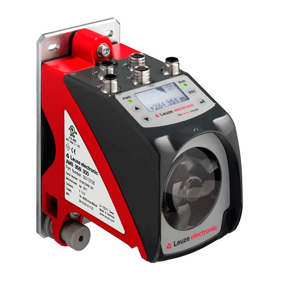
Electrical work must be carried out by a certified electrician. Attention, laser radiation! The AMS 358i operates with a red light laser of class 2 acc. to EN 60825-1. If you look into the beam path over a longer time period, the retina of your eye may be damaged! - Page 12 For EtherNet-based devices, the MAC ID is specified on the name plate. Please note that the shown name plate is for illustration purposes only; the contents do not correspond to the original. Figure 2.1: Location of the name plate on the AMS 358 AMS 358 Leuze electronic...
-
Page 13: Fast Commissioning / Operating Principle
Fast commissioning / operating principle Fast commissioning / operating principle Notice! Below, you will find a short description for the initial commissioning of the AMS 358i. Detailed explanations for the listed points can be found throughout the handbook. Mounting the AMS... -
Page 14: Connecting The Voltage Supply
Address assignment (manual or automatic via DHCP or BootP) Deactivate parameter enabling Configure the participant Transfer the data to the control Configuration of the config assembly, when doing so observe chapter 9.6 without fail Use explicit messaging services AMS 358 Leuze electronic... - Page 15 Parameter handling -> Parameter enable menu. Configuring the participant (e.g., in the RSLogix 5000). In the RSLogix 5000 configuration tool for EtherNet/IP, a so-called "Generic EtherNet Module" is created for the AMS 358i under the "Communication" path. Leuze electronic AMS 358...
- Page 16 The config assembly must include all parameters that affect the AMS 358i. The config assembly is automatically written to the connected participants in cycles that the control manufacturer defines.
- Page 17 Explicit messaging services (e.g., "get attributes …, set attribute …, and others) can be used to acyclically access all data of the AMS 358i Attention! If parameters are changed via explicit messaging services while simultaneously activating a configuration assembly, the changed parameters must subsequently be entered in the configuration assembly. Leuze electronic AMS 358...
-
Page 18: Specifications
Device type / 22 (encoder) Position sensor type (absolute encoder) Operating and display elements Keyboard 4 buttons Display monochromatic graphical display, 128 x 64 pixels 4 LEDs, 2 of which are used to display the EtherNet/IP connection 358i Leuze electronic... - Page 19 A 100% prevention of the formation of condensation cannot be guaran- teed due to the limited heating capacity of the AMS 358i. This is a Class A product. In a domestic environment this product may cause radio interference, in which case the operator may be required to take adequate measures.
-
Page 20: Dimensioned Drawing Ams 358I
Dimensioned drawing AMS 358i M 5 screw for alignment Knurled nut with WAF 4 hexagon socket and M 5 nut for securing Optical axis Zero point of the distance to be measured Figure 4.1: Dimensioned drawing AMS 358 358i Leuze electronic... -
Page 21: Type Overview Ams 358I
120 m operating range, EtherNet/IP interface, integrated heating 50113730 AMS 358 200 H 200 m operating range, EtherNet/IP interface, integrated heating 50113731 AMS 358 300 H 300 m operating range, EtherNet/IP interface, integrated heating 50113732 Table 4.1: Type overview AMS 358 Leuze electronic 358i... -
Page 22: Installation And Mounting
Device name plate using the AMS 300 as an example Notice! Please note that the shown name plate is for illustration purposes only; the contents do not correspond to the original. Save the original packaging for later storage or shipping. AMS 358 Leuze electronic... -
Page 23: Mounting The Ams 358
Installation and mounting If you have any questions concerning your shipment, please contact your supplier or your local Leuze electronic sales office. Observe the applicable local regulations when disposing of the packaging materials. Mounting the AMS 358i M 5 screw for... - Page 24 ("B" in figure 5.2). Knurled nut and nut must not be tightened until alignment has been completed. Attention! The device must not be opened. Failure to comply will render the guarantee void. Warranted features cannot be guaranteed after the device has been opened. AMS 358 Leuze electronic...
-
Page 25: Optional Mounting Bracket
Optional mounting bracket A mounting bracket for mounting the AMS 358i on a flat, horizontal surface is available as an optional accessory. Type designation: MW OMS/AMS 01 Part No.: 50107255 Laser beam Figure 5.3: Optional mounting bracket Leuze electronic AMS 358... -
Page 26: Mounting Distances
Depending on the size of the used reflector, the optical data trans- ceiver can be mounted with a minimum mounting spacing of 100 mm to the AMS 358i. The mounting spacing is independent of the distance. -
Page 27: Mounting The Ams 358 With Laser Beam Deflector Unit
AMS 358i… and the deflection mirror as well as between the mirror and the reflector. Use the M5 screws to mount the deflector unit. Secure the screws with a toothed lock washer to protect against loosening caused by vibrations. -
Page 28: Dimensioned Drawing Of Us Ams 01 Deflector Unit
Installation and mounting 5.3.2 Dimensioned drawing of US AMS 01 deflector unit Laser beam Figure 5.6: Dimensioned drawing of US AMS 01 deflector unit AMS 358 Leuze electronic... -
Page 29: Mounting The Us 1 Oms Deflector Unit Without Mounting Bracket
A Mirror Figure 5.7: Photo and dimensioned drawing of the US 1 OMS deflector unit Alignment of the laser light spot on the reflector is performed as described in chapter 5.2. Leuze electronic AMS 358... -
Page 30: Reflectors
358i measures distances against a reflective tape specified by Leuze electronic. All provided specifications for the AMS 358i, such as the operating range or accuracy, can only be achieved with the reflective tape specified by Leuze electronic. The reflective tapes are available as adhesive tapes, affixed to a metal plate and with an integrated heater especially for use at low temperatures. -
Page 31: Specifications Of The Self-Adhesive Foil
Do not use any agents that act with a grinding effect. A conventional household Cleaning detergent can be used as a cleaning agent. Rinse with clear water and dry the surface. Storing the reflector Store in a cool and dry place. Leuze electronic AMS 358... -
Page 32: Dimensioned Drawing Of Reflective Tape On A Metal Plate
Dimensioned drawing of reflective tape on a metal plate Always align the TOP marking with the AMS connections! (chapter 6.4.2) Figure 6.1: Dimensioned drawing of reflectors Part Reflective tape (mm) Reflector plate (mm) Reflective tape 200x200-M Reflective tape 500x500-M Reflective tape 914x914-M AMS 358 Leuze electronic... -
Page 33: Specifications Of Heated Reflectors
Do not use any agents that act with a grinding effect. A conventional house- Cleaning hold detergent can be used as a cleaning agent. Rinse with clear water and dry the surface. Storing the reflector Store in a cool and dry place. Leuze electronic AMS 358... -
Page 34: Dimensioned Drawing Of Heated Reflectors
L ± 0,5 XL ± 1 Si cable 3 x 0.75 mm² Figure 6.2: Dimensioned drawing of heated reflectors Part Reflective tape (mm) Insulated base plate (mm) Reflective tape 200x200-H Reflective tape 500x500-H Reflective tape 914x914-H AMS 358 Leuze electronic... -
Page 35: Selecting Reflector Sizes
Attention! The reflector sizes shown below are a recommendation from Leuze electronic for on-vehicle mounting of the AMS 358i. For stationary mounting of the AMS 358i, a smaller reflector is generally sufficient for all measurement distances. On the basis of the system planning and design, always check whether mechanical travel tolerances may require the use of a reflector larger than that which is recommended. -
Page 36: Mounting The Reflector
For this purpose, use the alignment elements provided on the AMS 358i… (see chapter 5.2 "Mounting the AMS 358i"). If necessary, remove the protective foil from the reflector. - Page 37 Reflective tapes …-S and …-M Pitch 1 ° Direct reflection from the triad structure Deflected surface reflection due to the pitch of the reflective tape Figure 6.3: Reflector mounting Pitch 1 ° Spacer sleeves Figure 6.4: Pitch of the reflector Leuze electronic AMS 358...
- Page 38 Direct reflection from the triad structure Deflected surface reflection due to the pitch of the reflective tape Figure 6.5: Mounting of heated reflectors Pitch approx. 1 ° Spacer sleeves Figure 6.6: Pitch of the heated reflector AMS 358 Leuze electronic...
-
Page 39: Table Of Reflector Pitches
Notice! Reliable function of the AMS 358i and, thus, max. operating range and accuracy can only be achieved with the reflective tape specified by Leuze electronic. No function can be guaranteed if other reflectors are used! Leuze electronic AMS 358... -
Page 40: Electrical Connection
The laser measurement systems are designed in accordance with safety class III for supply by PELV (protective extra-low voltage with reliable disconnection). Notice! Protection class IP65 is achieved only if the connectors and caps are screwed into place! AMS 358 Leuze electronic... -
Page 41: Pwr - Voltage Supply / Switching Input/Output
BUS IN (4-pin socket, D-coded) BUS IN Name Remark Transmit Data + Receive Data + Transmit Data - TD+ 1 Receive Data - Thread Functional earth (housing) M 12 socket (D-coded) Table 7.2: Pin assignments for BUS IN Leuze electronic AMS 358... -
Page 42: Ethernet/Ip Bus Out
Voltage supply 0 V DC RS232-RX Receiving line RS 232/service data Not used RS232-RX M 12 socket Thread Functional earth (housing) (A-coded) Table 7.4: Service pin assignments Notice! The service interface is designed only for use by Leuze electronic! AMS 358 Leuze electronic... -
Page 43: Display And Control Panel Ams 358
Display and control panel AMS 358i Display and control panel AMS 358i Structure of the control panel Status display Bus/interface info Bar graph Distance measurement value Control buttons Figure 8.1: Structure of the control panel using the AMS 304 PROFIBUS device variant as an example Status display and operation 8.2.1... - Page 44 Display and control panel AMS 358i Plausibility error: Implausible measurement value. Possible causes: light beam interruption, outside of measurement range, permissible internal device temperature considerably exceeded or traverse rate >10m/s. Depending on the configuration, either zero or the last valid measurement value is output at the interfaces.
-
Page 45: Led Status Displays
Display and control panel AMS 358i 8.2.2 LED status displays After power ON, a test of the Power LED and Net LED is performed in the following sequence: LEDs off. LEDs are switched to green for approx. 0.25 s. LEDs are switched to red for approx. 0.25 s. - Page 46 Display and control panel AMS 358i Net LED Net LED off - No voltage supply Flashing green Net LED flashes green - LED function test for 0.25 s after power up - No EtherNet/IP communication present - AMS 358i is not assigned to any master...
-
Page 47: Control Buttons
Display and control panel AMS 358i 8.2.3 Control buttons Navigate upward/laterally. Down Navigate downward/laterally. Exit menu item. ENTER Confirm/enter value, change menu levels. Navigating within the menus The menus within a level are selected with the up/down buttons The selected menu item is activated with the enter button Press the ESC button to move up one menu level. -
Page 48: Menu Description
Display and control panel AMS 358i Menu description 8.3.1 The main menus After voltage has been applied to the laser, device information is displayed for several seconds. The display then shows the measurement window with all status information. Device information - main menu... -
Page 49: Parameter Menu
Display and control panel AMS 358i Notice! The rear cover of this manual includes a fold-out page with the complete menu structure. It describes the menu items in brief. 8.3.2 Parameter menu Parameter handling submenu The following functions can be called up in the Parameter handling submenu: •... - Page 50 Display and control panel AMS 358i Table 8.2: EtherNet/IP submenu Level 3 Level 4 Level 5 Selection/configuration option Standard Description Net mask The net mask can be set to any value in the ---.---.---.--- format. Usually, the AMS 358 is used in a private Class C network and the default setting can be accepted without change.
- Page 51 Display and control panel AMS 358i I/O submenu Table 8.4: I/O submenu Level 3 Level 4 Level 5 Selection/configuration option Standard Description I/O 1 Port config- Input/Output Output uration Defines whether I/O 1 functions as an output or input. Switching...
-
Page 52: Language Selection Menu
Display and control panel AMS 358i Other submenu Table 8.5: Other submenu Level 3 Level 4 Level 5 Selection/configuration option Standard Description Heating control Standard (10° C … 15° C)/Extended (30° C … 35° ) Standard Defines a switch-on/switch-off range for the heating control. -
Page 53: Service Menu
Display and control panel AMS 358i 8.3.4 Service menu Service Status messages Diagnostics Expanded diagnostics A more detailed description of the individual functions can be found in chapter 10. Operation Described here is an operating process using parameter enabling as an example. - Page 54 Parameter entry on the AMS 358i can be protected with a password. With the AMS 358i, the password is defined via the EDS file (class 100, instance 1) or via the configuration assembly. Thus, the password cannot be changed by means of display entry.
- Page 55 Display and control panel AMS 358i After parameter enabling is deactivated, all changes made on the display are overwritten by the configuration assembly (see above). If a new password has been assigned, this, too, is overwritten by the password defined in the configuration assembly.
-
Page 56: Ethernet/Ip Interface
Within the AMS 358i, the input and output assemblies for transferring measurement values by means of UDP are transferred and are thereby deterministically available in a cycle config- ured via the control. - Page 57 Notice! The AMS 358i communicates via the Common Industrial Protocol (CIP). CIP Safety, CIP Sync and CIP Motion are not supported by the AMS 358i. The EDS file for the AMS 358i can be found on the Leuze website at: www.leuze.com ->...
-
Page 58: Topology
Select the Gateway menu item. Enter the gateway address and save your entry with save. Select the Net mask menu item. Enter the address of the net mask and save your entry with save. Deactivate parameter enabling. AMS 358 Leuze electronic... - Page 59 ---.---.---.--- EtherNet interface Activation Address Gateway Net mask DHCP activated BootP activated EtherNet interface Activation Address Gateway Net mask DHCP activated BootP activated The complete menu structure can be found at the end of the description. Leuze electronic AMS 358...
-
Page 60: Ethernet/Ip Device Class
9.4.1 Communication / EDS file The EDS file is an integral part of the AMS 358i. All AMS 358i data can be called up via the object-, instance- and attribute addresses described in the following. -
Page 61: Ethernet/Ip - Electrical Connection
Thread Functional earth (housing) Thread Functional earth (housing) Figure 9.1: EtherNet/IP - Electrical connection Notice! For contacting BUS IN and BUS OUT, we recommend our ready-made EtherNet cable (see chapter 11.4.5 "Accessory ready-made cables for EtherNet/IP"). Leuze electronic AMS 358... -
Page 62: Eds File - General Info
EtherNet/IP interface EDS file - general info An EDS file (Electronic Data Sheet) is provided for the AMS 358i. The EDS file is named "AMS358i.eds"; the corresponding icon is named "AMS358i.ico" Both files are available in the Download area of the Leuze website: www.leuze.com. - Page 63 0 (zero). When using the configuration assembly, it is, therefore, mandatory that the individual parameters be manually transferred from the manual (see chapter 9.7.8.5 "Config- uration assembly"). Example definition of input, output and configuration assembly in the RSLogix 5000 from Rockwell Automation. Leuze electronic AMS 358...
-
Page 64: Eds File - Detailed Description
Leuze electronic as an encoder. According to ODVA, the 358i is assigned number 34 = 22 9.7.1.3 Product code The product code is an ID assigned by Leuze electronic that has no further impact on other objects. 9.7.1.4 Revision Version number of the identity object. AMS 358... - Page 65 AMS 358i. The default entry of 0 (zero) does not change. 9.7.1.10 Heartbeat Interval The attribute sets a time interval in which a "heartbeat message" is sent by the AMS 358i. The value is entered in seconds.
-
Page 66: Class 35 Position Sensor Object
9.7.2.1 Position value Attribute 10 Read position value. Attr. Byte Bit 7 Bit 6 Bit 5 Bit 4 Bit 3 Bit 2 Bit 1 Bit 0 Position value (low byte) Position value Position value Position value (high byte) AMS 358 Leuze electronic... - Page 67 9.7.2.5 Velocity value Attribute 24 Read velocity value. Attr. Byte Bit 7 Bit 6 Bit 5 Bit 4 Bit 3 Bit 2 Bit 1 Bit 0 Velocity value (low byte) Velocity value Velocity value Velocity value (high byte) Leuze electronic AMS 358...
- Page 68 12. The counting direction is output in bit 0. 0 = positive counting direction 1 = negative counting direction Bits 1 - 7 have no meaning and have status 0. AMS 358 Leuze electronic...
- Page 69 The PLB and ERR status messages generated by AMS 358i are entered in bit 0 and bit 1. The alarms entered here result in incorrect measurement values on the AMS 358i. The CIP spec. distinguishes between alarms and warnings. The following applies for PLB and ERR:...
- Page 70 Status messages ATT, LSR and TMP are entered as warnings by the AMS 358i. For this purpose, an area is reserved in the CIP spec. for device-specific data (bits 13-15).
- Page 71 Activation of the preset value via attribute 101. 9.7.2.20 Preset reset Attribute 104 The attribute is used for deleting the set preset value. The preset status (attribute 102) is set to inactive. 1 = delete preset value. Leuze electronic AMS 358...
- Page 72 Attribute 108 Measurement value at the interface = measured distance + offset. The attribute sets an offset to the measured value in the AMS 358i. The offset takes imme- diate effect following instruction "set attribute single class1 instance1 attribute108". Attr.
-
Page 73: Class 100 Display Configuration
The following table provides information on the languages available for selection. Language Value English German Italian Spanish French 9.7.3.2 Password protection Attribute 2 The attribute activates password protection. 1 = password protection active 0 = password protection inactive Leuze electronic AMS 358... -
Page 74: Class 101 Selection Assembly
This attribute is used to activate extended heating control. The extended heating control range of the internal device heating may prevent condensation from forming on the optics of the AMS 358i. The internal heating of the AMS 358i is switched on at higher ambient temperatures (30 °C) if the parameter is set. - Page 75 No individual assemblies can be created by the customer, since these are a component of the EDS file supplied by Leuze. A detailed description of the assemblies offered by Leuze electronic can be found beginning with chapter 9.7.8. 9.7.4.2 Output assembly Attribute 2 The attribute makes available an assembly for outputs.
-
Page 76: Class 103 Switching Inputs/Outputs
Activation (high/low active) BYTE Output function WORD Input function BYTE Status (input/output) BYTE Activation output BYTE 9.7.5.1 Definition of input/output Instance 1, attribute 1 (PIN 2/M 12 Power) Instance 2, attribute 1 (PIN 4/M 12 Power) AMS 358 Leuze electronic... - Page 77 9.7.5.3 Function assignment of the inputs Instance 1, attribute 4 (PIN 2/M 12 Power) Instance 2, attribute 4 (PIN 4/M 12 Power) Attribute 4 defines which function is to be triggered when the input is set in the AMS 358i. Bit 7 Bit 6...
- Page 78 9.7.5.8 Activation output (dynamic output) Instance 1, attribute 6 (PIN 2/M 12 Power) Instance 2, attribute 6 (PIN 4/M 12 Power) With the dynamic output, the hardware outputs (PIN 2/PIN 4) can be set via the control soft- ware. AMS 358 Leuze electronic...
-
Page 79: Class 104 Behavior In The Case Of Error
The attribute specifies whether the PLB status bit (implausible measurement value) is set immediately or after the "error delay time - position" elapses. 0 = PLB status bit is set immediately 1 = PLB status bit is set with a delay Leuze electronic AMS 358... - Page 80 The attribute specifies whether—in the case of an error—the velocity value immediately outputs the value of attribute 5 (0 or last valid value) or the last valid velocity value for the configured error delay time (attribute 8). 0 = error delay deactivated 1 = error delay activated AMS 358 Leuze electronic...
-
Page 81: Class 105 Velocity Monitoring
Switching mode BYTE Direction selection BYTE Velocity limit value UINT 20.000 Velocity hysteresis UINT 20.000 Limit value range start DINT -999.999 999.999 Limit value range end DINT -999.999 999.999 Limit value status BYTE Limit value comparison BYTE Leuze electronic AMS 358... - Page 82 "5500" to "5000". The limit value is not active in the opposite direction. If the check is independent of direction, the order of range start and range end is irrelevant. AMS 358 Leuze electronic...
- Page 83 1 = limit values exceeded. 9.7.7.9 Velocity limit value - limit value comparison Attribute 9 The attribute indicates whether the respective velocity limit value is compared with the configured limit value. 0 = comparison inactive 1 = comparison active Leuze electronic AMS 358...
-
Page 84: Class 4 Assembly
Byte 5: AMS 358i alarms and warnings Byte 6 - Byte 7: reserved Inst. Byte Bit 7 Bit 6 Bit 5 Bit 4 Bit 3 Bit 2 Bit 1 Bit 0 Position value (low byte) AMS 358 Leuze electronic... - Page 85 1 = ON 1 = ON 1 = ON 1 = ON 1 = ON 0 = OFF 0 = OFF 0 = OFF 0 = OFF 0 = OFF Notice! Negative values are displayed in two's complement. Leuze electronic AMS 358...
- Page 86 Preset value (low byte) Preset value Preset value Preset value (high byte) Preset reset Preset teach 1 = ON 1 = ON 0 = OFF 0 = OFF Notice! Negative values are displayed in two's complement. AMS 358 Leuze electronic...
- Page 87 Only parameters that are also entered in the configuration assembly can be taken into account in all operating situations of the AMS 358i. Parameters that are set by explicit calls but are not entered in the configuration assembly may, therefore, act only temporarily. The next time the configuration assembly is automatically downloaded to the AMS 358i, these explicitly transferred parameters are again overwritten.
- Page 88 0 0 0 0 0 0 0 0 105 / 3 / 1 Activation velocity monitoring -- -- -- -- -- -- -- 0 105 / 3 / 2 Switch type limit value exceeded/not met -- -- -- -- -- -- -- 0 AMS 358 Leuze electronic...
- Page 89 In byte 1 to 4, the formats for the position value as well as for the velocity value are defined. The formats for velocity and position value must be the same. Example: Position value format metric = velocity value format metric Different formats such as position value metric and velocity value inch are not allowed. Leuze electronic AMS 358...
-
Page 90: Diagnostics And Troubleshooting
Diagnostics and troubleshooting Diagnostics and troubleshooting 10.1 Service and diagnostics in the display of the AMS 358i In the main menu of the AMS 358i, expanded "Diagnostics" can be called up under the Service heading. Service Status messages Diagnostics Expanded diagnostics... -
Page 91: 10.1.2 Diagnostics
Leuze for internal evaluation. The diagnostics have no influence on the communication to the host interface and can be activated during operation of the AMS 358i. 10.1.3 Expanded diagnostics The Expanded diagnostics menu item is used for Leuze-internal evaluation. - Page 92 LINK LED for BUS OUT Green continuous light LINK LED green - The link exists, the hardware connection to the next connected participant is OK. Yellow flashing LINK LED flashes yellow - Data is exchanged with the connected participants. AMS 358 Leuze electronic...
-
Page 93: 10.2.1 Power Led
Net LED "flashes green" Check configuration in the control. The AMS 358 is not listed in the scan list of the master The AMS 358i is not assigned to any master Net LED "flashes green/ Check configuration in the control. - Page 94 Customer data (please complete) Device type: Company: Contact partner / department: Phone (direct): Fax: Street / No: ZIP code/City: Country: Leuze Service fax number: +49 7021 573 - 199 AMS 358 Leuze electronic...
-
Page 95: Type Overview And Accessories
120 m operating range, EtherNet/IP interface, integrated heating 50113730 AMS 358 200 H 200 m operating range, EtherNet/IP interface, integrated heating 50113731 AMS 358 300 H 300 m operating range, EtherNet/IP interface, integrated heating 50113732 Table 11.1: Type overview AMS 358 Leuze electronic AMS 358... -
Page 96: Overview Of Reflector Types
M 12 connector, EtherNet, D-coded, BUS IN, BUS OUT 50112155 KDS ET M12/RJ45 W - 4P Converter from M 12 D-coded to RJ45 socket 50109832 KD 095-5A M 12 connector, A-coded socket, Power (PWR) 50020501 Table 11.5: Accessory M 12 connector AMS 358 Leuze electronic... -
Page 97: 11.4.4 Accessory Ready-Made Cables For Voltage Supply
Part No. K-D M12A-5P-5m-PVC M 12 socket, A-coded, axial plug outlet, open cable end, 50104557 cable length 5 m K-D M12A-5P-10m-PVC M 12 socket, A-coded, axial plug outlet, open cable end, 50104559 cable length 10 m Leuze electronic AMS 358... -
Page 98: 11.4.5 Accessory Ready-Made Cables For Ethernet/Ip
Cable designation: KB ET - … - SA Accessories M 12 EtherNet/IP connection cable with both-sided D-coded M 12 plug Cable designation: KB ET - … - SSA Accessories EtherNet/IP connection cable, M 12-/RJ45 Cable designation: KB ET - … - SA-RJ45 AMS 358 Leuze electronic... - Page 99 Cable length 15 m 50106902 KB ET - 20000 - SSA Cable length 20 m 50106903 KB ET - 25000 - SSA Cable length 25 m 50106904 KB ET - 30000 - SSA Cable length 30 m 50106905 Leuze electronic AMS 358...
-
Page 100: Maintenance
Contact your Leuze distributor or service organization should repairs be required. The addresses can be found on the inside of the cover and on the back. Notice! When sending the laser measurement systems to Leuze electronic for repair, please provide an accurate description of the error. 12.3... - Page 101 Specifications ..... 30 Dimensioned drawing ....25 Leuze electronic 358i...
- Page 102 Name plates ......19 Net LED ......43 358i Leuze electronic...
- Page 103 Surface reflections ....34 Symbols ......5 Leuze electronic 358i...
- Page 104 Menu structure AMS 358i Level 1 Level 2 Level 3 Level 4 Level 5 Selection/configuration option Detailed infor- mation on : selection : selection : selection : selection : selection : selection : back : back : back : back : activate : back Device information...
- Page 105 57.6 kbit/s / 115.2 kbit/s Format 8,e,1 / 8,n,1 Language selection Deutsch / English / Español / Français / Italiano page 49 Service Status messages page 50 Diagnostics Exclusively for service purposes by Leuze electronic Expanded diagnostics Exclusively for service purposes by Leuze electronic...
Need help?
Do you have a question about the AMS 358i and is the answer not in the manual?
Questions and answers