
Related Manuals for Leuze electronic AMS 355i


Summary of Contents for Leuze electronic AMS 355i
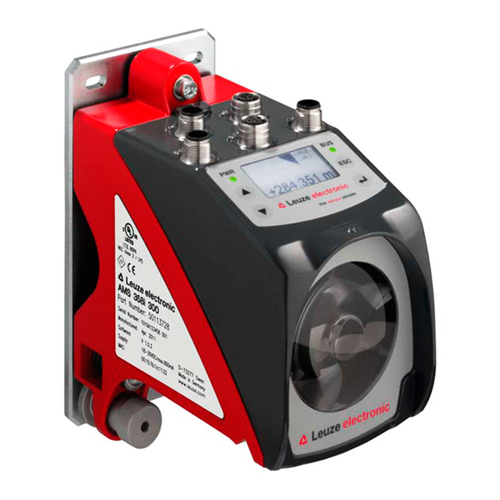
- Page 1 AMS 355i Optical laser measurement system – DeviceNet Original operating instructions We reserve the right to make technical changes EN 2021/04/30 - 50113345...
- Page 2 © 2021 Leuze electronic GmbH + Co. KG In der Braike 1 D-73277 Owen / Germany Phone: +49 7021 573-0 Fax: +49 7021 573-199 http://www.leuze.com info@leuze.de Leuze electronic GmbH + Co. KG AMS 355...
- Page 3 AMS 355 The main menus Device information - main menu AMS 355i 120 Leuze electronic This menu item contains detailed informa- tion on GmbH & Co. KG • Device type SW: V 1.3.0HW:1 • Manufacturer SN: ----------------------- • Software and hardware version •...
-
Page 4: Table Of Contents
Table of contents General information ..........5 Explanation of symbols . - Page 5 Table of contents Reflectors ........... . . 27 General information .
- Page 6 Table of contents DeviceNet electrical connection ..........56 Electrical data for Data V+ and Data V- supply voltage .
- Page 7 Table of contents Maintenance ........... 94 12.1 General maintenance information .
-
Page 8: General Information
Note! The Declaration of Conformity for these devices can be requested from the manufacturer. The manufacturer of the product, Leuze electronic GmbH & Co. KG in D-73277 Owen, possesses a certified quality assurance system in accordance with ISO 9001. Leuze electronic GmbH + Co. KG... -
Page 9: Description Of Functions Ams 355 I
Note that each interface version listed below corresponds to a different AMS 3xx model. AMS 304 AMS 348 AMS 355 AMS 358 AMS 335 AMS 338 AMS 308 AMS 384 AMS 301 AMS 300 AMS 355 Leuze electronic GmbH + Co. KG... -
Page 10: Safety
Leuze electronic GmbH + Co. KG is not liable for damages caused by improper use. Read the technical description before commissioning the device. Knowledge of this ... -
Page 11: Competent Persons
Exemption of liability Leuze electronic GmbH + Co. KG is not liable in the following cases: • The device is not being used properly. • Reasonably foreseeable misuse is not taken into account. -
Page 12: Laser Safety Notices
The device must not be tampered with and must not be changed in any way. There are no user-serviceable parts inside the device. Repairs must only be performed by Leuze electronic GmbH + Co. KG. NOTE Affix laser information and warning signs! Laser information and warning signs are attached to the device (see figure 2.1). - Page 13 Safety A Laser aperture B Laser warning sign C Laser information sign with laser parameters Figure 2.1: Laser apertures, laser warning signs AMS 355 Leuze electronic GmbH + Co. KG...
- Page 14 18 μs 18 μs Wavelength: 655 nm 655 nm CLASS 2 LASER PRODUCT IEC 60825-1:2014 Complies with 21 CFR 1040.10 IEC 60825-1:2014 Figure 2.2: Laser warning and information signs – supplied stick-on labels Leuze electronic GmbH + Co. KG AMS 355...
-
Page 15: Fast Commissioning / Operating Principle
Fast commissioning / operating principle Fast commissioning / operating principle Note! Below you will find a short description for the initial commissioning of the AMS 355i. Detailed explanations for the listed points can be found throughout the handbook. Mounting the AMS 355... -
Page 16: Connecting The Voltage Supply
On the AMS 355 , the baud rate is set via the control panel/display. Communication with the AMS 355 is only possible if the baud rates match. Detailed information can be found in Chapter 9. Leuze electronic GmbH + Co. KG AMS 355... -
Page 17: Technical Data
125kbit/s (default) / 250kbit/s / 500kbit/s Vendor ID / 20C Device type / 22 (encoder) Position sensor type (absolute encoder) Controls and indicators Keyboard 4 keys Display Monochromatic graphical display, 128 x 64 pixels 2 LEDs, two-colored AMS 355 Leuze electronic GmbH + Co. KG... - Page 18 This is a Class A product. In a domestic environment this product may cause radio interference, in which case the operator may be required to take adequate measures. The AMS 355 is designed in accordance with protection class III for supply with PELV (protective extra-low voltage). Leuze electronic GmbH + Co. KG AMS 355...
-
Page 19: Ams 355 Dimensioned Drawing
M5 screw for alignment Knurled nut with WAF4 hexagon socket and M5 nut for securing Optical axis Zero point of the distance to be measured Figure 4.1: AMS 355 dimensioned drawing AMS 355 Leuze electronic GmbH + Co. KG... -
Page 20: Overview Of Ams 355 I Types
50113722 AMS 355 200 H 200m operating range, DeviceNet interface, integrated heating 50113723 AMS 355 300 H 300m operating range, DeviceNet interface, integrated heating 50113724 Table 4.1: Overview of AMS 355 types Leuze electronic GmbH + Co. KG AMS 355... -
Page 21: Installation And Mounting
Note! Please note that the shown name plate is for illustration purposes only; the contents do not correspond to the original. Save the original packaging for later storage or shipping. AMS 355 Leuze electronic GmbH + Co. KG... -
Page 22: Mounting The Ams 355 I
AMS 355 and the reflector. Use M5 screws to fasten the laser measurement system. Secure the screws with a lock washer to protect against loosening caused by vibrations. Leuze electronic GmbH + Co. KG AMS 355... - Page 23 ). Knurled nut and nut must not be tightened until alignment Figure 5.2 has been completed. Attention! The device must not be opened. Failure to comply will render the guarantee void. Warranted features cannot be guaranteed after the device has been opened. AMS 355 Leuze electronic GmbH + Co. KG...
-
Page 24: Optional Mounting Bracket
A mounting bracket for mounting the AMS 355 on a flat, horizontal surface is available as an optional accessory. Type designation: MW OMS/AMS 01 Part no.: 50107255 Laser beam Figure 5.3: Optional mounting bracket Leuze electronic GmbH + Co. KG AMS 355... -
Page 25: Parallel Mounting Of The Ams 355
Measurement distance up to 120m: minimum parallel spacing X ≥ 600mm Measurement distance up to 200m: minimum parallel spacing X ≥ 750mm Measurement distance up to 300m: minimum parallel spacing X ≥ 750mm AMS 355 Leuze electronic GmbH + Co. KG... -
Page 26: Parallel Mounting Of Ams 355 I And Ddls Optical Data Transmission
Depending on the size of the used reflector, the DDLS can be mounted with a minimum parallel spacing of 100mm to the AMS 355 . The parallel spacing is independent of the distance. Leuze electronic GmbH + Co. KG AMS 355... -
Page 27: Mounting The Ams 355 I With Laser Beam Deflector Unit
Use the M5 screws to mount the deflector unit. Secure the screws with a lock washer to protect against loosening caused by vibrations. Figure 5.5: Mounting variants of the US AMS 01 laser beam deflector unit AMS 355 Leuze electronic GmbH + Co. KG... -
Page 28: Dimensioned Drawing Of Us Ams 01 Deflector Unit
Installation and mounting 5.3.2 Dimensioned drawing of US AMS 01 deflector unit Laser beam Figure 5.6: Dimensioned drawing of US AMS 01 deflector unit Leuze electronic GmbH + Co. KG AMS 355... -
Page 29: Mounting The Us 1 Oms Deflector Unit Without Mounting Bracket
Height of the spring in non- preloaded state A Mirror Figure 5.7: Photo and dimensioned drawing of the US 1 OMS deflector unit The laser light spot is aligned with the reflector as described in Chapter 5.2. AMS 355 Leuze electronic GmbH + Co. KG... -
Page 30: Reflectors
Table 6.1 "Reflector pitch resulting from spacer sleeves" on page 36. The reflective tapes have a protective film that is easy to peel off. It must be removed from the reflector before the complete system is put into operation. Leuze electronic GmbH + Co. KG AMS 355... -
Page 31: Technical Data Of Self-Adhesive Tape
Do not use any abrasive agents. A conventional household detergent Cleaning can be used as a cleaning agent. Rinse with clear water and dry the surface. Reflector storage Store in a cool and dry place. AMS 355 Leuze electronic GmbH + Co. KG... -
Page 32: Dimensioned Drawing Of Reflective Tape On Carrier Plate
Always align the TOP marking with the AMS connections! (Chapter 6.4.2) Figure 6.1: Dimensioned drawing of reflectors Article Reflective tape (mm) Reflector plate (mm) Reflective tape 200x200-M Reflective tape 500x500-M Reflective tape 914x914-M Leuze electronic GmbH + Co. KG AMS 355... -
Page 33: Technical Data Of Heated Reflectors
Do not use any abrasive agents. A conventional household Cleaning detergent can be used as a cleaning agent. Rinse with clear water and dry the surface. Reflector storage Store in a cool and dry place. AMS 355 Leuze electronic GmbH + Co. KG... -
Page 34: Dimensioned Drawing Of Heated Reflectors
XL ± 1 Si cable 3 x 0.75mm² Figure 6.2: Dimensioned drawing of heated reflectors Article Reflective tape (mm) Insulated carrier plate (mm) Reflective tape 200x200-H Reflective tape 500x500-H Reflective tape 914x914-H Leuze electronic GmbH + Co. KG AMS 355... -
Page 35: Selecting Reflector Size
Reflective tape 914x914-S 50108988 Reflective tape 914x914-H 50115022 AMS 355 300 (max. 300m) 749x914mm Reflective tape 749x914-S 50104363 914x914mm Reflective tape 914x914-M 50104366 Reflective tape 914x914-S 50108988 Reflective tape 914x914-H 50115022 For landside mounting AMS 355 Leuze electronic GmbH + Co. KG... -
Page 36: Mounting The Reflector
For this purpose, use the alignment elements provided on the AMS 355 … (see chapter 5.2 "Mounting the AMS 355i"). If necessary, remove the protective film from the reflector. Attention! The "TOP" label on the reflectors should be aligned the same as the connections of the... - Page 37 Direct reflection due to the triple structure Deflected surface reflection due to the pitch of the reflective tape Figure 6.3: Mounting the reflector Pitch approx. 1° Spacer sleeves Figure 6.4: Pitch of the reflector AMS 355 Leuze electronic GmbH + Co. KG...
- Page 38 Direct reflection due to the triple structure Deflected surface reflection due to the pitch of the reflective tape Figure 6.5: Mounting of heated reflectors Pitch approx. 1° Spacer sleeves Figure 6.6: Pitch of the heated reflector Leuze electronic GmbH + Co. KG AMS 355...
-
Page 39: Table Of Reflector Pitches
Reliable operation of the and, thus, max. operating range and accuracy can only AMS 355 be achieved with the reflective tape specified by Leuze. Correct operation cannot be guar anteed if other reflectors are used! AMS 355 Leuze electronic GmbH + Co. KG... -
Page 40: Electrical Connection
For UL applications, use is only permitted in Class 2 circuits in accordance with the NEC (National Electric Code). The laser measurement systems are designed in accordance with protection class III for sup ply by PELV (protective extra-low voltage with reliable disconnection). Leuze electronic GmbH + Co. KG AMS 355... -
Page 41: Pwr - Voltage Supply / Switching Input/Output
CAN_L Data V+ supply voltage Data V- supply voltage DRAIN CAN_H Data signal CAN_H CAN_L Data signal CAN_L M12 connector Thread Functional earth (housing) (A-coded) Table 7.2: DeviceNet BUS IN pin assignment AMS 355 Leuze electronic GmbH + Co. KG... -
Page 42: Devicenet Bus Out
RS232-RX Receiving line RS 232/service data RS232-RX Not used M12 socket (A-coded) Thread Functional earth (housing) Table 7.4: Pin assignment - Service Note! The service interface is designed only for use by Leuze! Leuze electronic GmbH + Co. KG AMS 355... -
Page 43: Display And Control Panel Ams 355I
Display and control panel AMS 355i Display and control panel AMS 355 Structure of the control panel Status indicator Bus/interface info Bar graph Distance measurement value Control buttons Figure 8.1: Structure of the control panel using the AMS 304 PROFIBUS device variant as... - Page 44 Display and control panel AMS 355i Plausibility error: Implausible measurement value. Possible causes: light beam interruption, outside of measurement range, permissible internal device temperature considerably exceeded or traverse rate >10m/s. Depending on the configuration, either zero or the last valid measurement value is output at the interfaces.
-
Page 45: Led Status Indicators
Display and control panel AMS 355i 8.2.2 LED status indicators After power ON, the Power LED and Net LED are tested as follows: LEDs off. LEDs are switched to green for approx. 0.25s. LEDs are switched to red for approx. 0.25s. -
Page 46: Control Buttons
Display and control panel AMS 355i - No data on the host interface Net LED Net LED off - The DUP MAC ID test is active - No voltage supply - The V+/V- voltage supply for the DeviceNet data driver is missing... -
Page 47: Menu Description
Display and control panel AMS 355i Navigating within the menus The menus within a level are selected with the up/down buttons The selected menu item is activated with the enter button Press the ESC button to move up one menu level. - Page 48 Display and control panel AMS 355i Device information - main menu AMS 355i 120 Leuze This menu item contains detailed information on • Device type GmbH & Co. KG • Manufacturer SW: V 1.3.0 HW:1 • Software and hardware version SN: --------------- •...
-
Page 49: Parameter Menu
Display and control panel AMS 355i 8.3.2 Parameter menu Parameter handling submenu The following functions can be called up in the Parameter handling submenu: • Lock and enable parameter entry • Set up a password • Reset the AMS 355 to the default settings Table 8.1:... - Page 50 Display and control panel AMS 355i Position value submenu Note! The parameters named under position value are to be set via the EDS file of the AMS 355 If parameters from the Position value submenu are changed via the display, these are over written via the EDS file stored in the control with the values stored there.
- Page 51 Display and control panel AMS 355i Table 8.4: I/O submenu Level 3 Level 4 Level 5 Selection/configuration option Standard Description Switching Function No function/teach preset/laser ON/OFF No function input Activa- Low active/High active Low active tion Switching Function Pos. limit value 1 / Pos. limit value 2 / Velocity /...
- Page 52 Display and control panel AMS 355i Other submenu Table 8.5: Other submenu Level 3 Level 4 Level 5 Selection/configuration option Standard Description Heating con- Standard (10°C … 15°C)/Extended (30°C … 35°) Standard trol Defines a switch-on/switch-off range for the heating control.
-
Page 53: Language Selection Menu
Display and control panel AMS 355i 8.3.3 Language selection menu Language selection o Deutsch English o Español o Français o Italiano 5 display languages are available: • German • English • Spanish • French • Italian The AMS 355 is delivered from the factory with the display preset to English. -
Page 54: Operation
Display and control panel AMS 355i Operation An operating process is described here using parameter enable as an example. Parameter enable During normal operation parameters can be viewed only. If parameters are to be changed, the ON menu item in the Parameter -> Parameter handling -> Parameter enable menu must be activated. - Page 55 Display and control panel AMS 355i According to the criteria specified by Rockwell Automation, Configuration Recovery auto matically downloads parameters to the AMS 355i. This results in parameters that were man ually changed via the display being restored by the control to the configured AMS...
-
Page 56: Devicenet Interface
In addition to the two signals for data transmission – CAN_L and CAN_H – the DeviceNet cable also provides two additional lines for supplying the network device or bus transceiver with power. Leuze electronic GmbH + Co. KG AMS 355... - Page 57 Max. length of all stub cables per network in m Thick cable =1 Mid cable = 2 Thin cable = 3 The ready-made data lines from Leuze correspond to the thin cable. AMS 355 Leuze electronic GmbH + Co. KG...
-
Page 58: Communication
Addressing of the attribute within the object instance. Service code (get, set, reset, start, stop and others...) The service code ultimately describes the type of access to the data, e.g., reading or writing. Leuze electronic GmbH + Co. KG AMS 355... -
Page 59: Devicenet Electrical Connection
355i is disconnected from the bus, all participants con nected to BUS OUT can then also no longer be addressed. For this reason, the ODVA recommends that these topologies not be used. AMS 355 Leuze electronic GmbH + Co. KG... -
Page 60: Electrical Data For Data V+ And Data V- Supply Voltage
DeviceNet Select the menu item DeviceNet MAC ID ( address) Enter a DeviceNet MAC ID between 0 and 63 (default: 63). Save the DeviceNet MAC ID with save Leuze electronic GmbH + Co. KG AMS 355... -
Page 61: Eds File - General Info
This stores the parameters defined in the EDS file in the control. If necessary, an automatic parameter download from the control to the takes place. AMS 355 Leuze recommends activating "Configuration Recovery". This stores all parameters in the control. AMS 355 Leuze electronic GmbH + Co. KG... - Page 62 "Laser off"--> Class 35; instance 1; attribute 110. Parameters are also marked with "Set" and written to the AMS. E.g. "Change the position format" --> Class 35; instance 1; attribute 15. Leuze electronic GmbH + Co. KG AMS 355...
-
Page 63: Eds File - Detailed Description
Byte 4: AMS 355 status Byte 5: AMS 355 alarms and warnings Inst. Byte Bit 7 Bit 6 Bit 5 Bit 4 Bit 3 Bit 2 Bit 1 Bit 0 Position value (low byte) AMS 355 Leuze electronic GmbH + Co. KG... - Page 64 1 = ON 1 = ON 1 = ON 0 = OFF 0 = OFF 0 = OFF 0 = OFF 0 = OFF Note! Negative values are shown in two's complement. Leuze electronic GmbH + Co. KG AMS 355...
-
Page 65: Class 1 Identity Object
Minor = 1 Minor = 1 127, Minor) USINT minor}; Minor = 999 Status WORD See CIP specification (5-2.2.1.5 status) Serial UDINT Manufacturer specific Number Product (max. 32) SHORT_STRI "AMS 355i" Name AMS 355 Leuze electronic GmbH + Co. KG... - Page 66 EDS file/object 1. This may have changed during a possible device exchange. The scanner would otherwise output an error message after a device is changed. 9.6.2.1 Vendor ID The Vendor ID assigned by ODVA for Leuze electronic GmbH + Co. KG is 524 9.6.2.2 Device type The AMS 355 is defined by Leuze as an encoder.
- Page 67 9.6.2.7 Product Name This attribute contains a short designation of the product. Devices with the same product code may have different "product names". AMS 355 Leuze electronic GmbH + Co. KG...
-
Page 68: Class 35 Position Sensor Object
From this address range, the AMS 355 uses only attributes that are func- tionally mapped in the AMS. The address range ≥ 100 is manufacturer-specific. 9.6.3.1 Position Value Attribute 10 Reading out position value. Leuze electronic GmbH + Co. KG AMS 355... - Page 69 If the position format is changed from inch to metric, the velocity format is internally changed automatically to millimeters per second. 9.6.3.5 Velocity value Attribute 24 Reading out velocity value. AMS 355 Leuze electronic GmbH + Co. KG...
- Page 70 12. The counting direction is output in bit 0. 0 = Positive counting direction 1 = Negative counting direction Bits 1 to 7 are irrelevant and have the status 0. Leuze electronic GmbH + Co. KG AMS 355...
- Page 71 Bit 1 = 1; ERR alarm is supported by the AMS 355 Bit 2 to bit 15 = 0 9.6.3.11 Alarm flag Attribute 46 The attribute evaluates the alarms supported in attribute 45, in an OR function (collective alarm). AMS 355 Leuze electronic GmbH + Co. KG...
- Page 72 The value is incremented in 1/10 hours for as long as the AMS 355 is connected to voltage. The value cannot be reset. 9.6.3.16 Preset value Attribute 100 The attribute enables the current position value to be set to a desired position value. Leuze electronic GmbH + Co. KG AMS 355...
- Page 73 Attribute 103 is toggled. 9.6.3.21 Direction of movement Attribute 105 At a velocity > 100mm/s, the attribute indicates the direction of movement. 0 = Positive direction of movement 1 = Negative direction of movement AMS 355 Leuze electronic GmbH + Co. KG...
-
Page 74: Class 100 Display Configuration
Attribute 110 This attribute is used to switch the laser on and off. 1 = Laser diode ON 0 = Laser diode OFF 9.6.4 Class 100 Display configuration Object class 100 = 64 Leuze electronic GmbH + Co. KG AMS 355... - Page 75 0 = Display illumination switches off 10 minutes after a button was last pressed 1 = Display illumination is always on AMS 355 Leuze electronic GmbH + Co. KG...
-
Page 76: Class 101 Assembly Selection
Customers cannot create their own assemblies because they are part of the EDS file supplied by Leuze. A detailed description of the assemblies offered by Leuze can be found from Chapter 9.6.1. Leuze electronic GmbH + Co. KG AMS 355... - Page 77 101. If the assemblies in object class 101 are changed, the storage area in the scanner for assemblies must be adapted. This is illustrated in the following screenshot from the RS Networx configuration tool: AMS 355 Leuze electronic GmbH + Co. KG...
-
Page 78: Class 103 Switching Inputs / Outputs
0 = Switching input reacts to a falling edge (transition from logical 1 to 0) 1 = Switching input reacts to a rising edge (transition from logical 0 to 1) Leuze electronic GmbH + Co. KG AMS 355... - Page 79 0 = from logical 1 to logical 0 if the "output" event occurs (see Attribute 3) 1 = from logical 0 to logical 1 if the "output" event occurs (see Attribute 3) AMS 355 Leuze electronic GmbH + Co. KG...
- Page 80 1 = The hardware output(s) are set as defined in attribute 2 Dynamic setting of the outputs is performed via 256 (256 = without taking the status messages bit 7 to bit 2 into consideration). Leuze electronic GmbH + Co. KG AMS 355...
-
Page 81: Class 104 Error Handling Procedures
1 immediately (0 or last valid value) or outputs the last valid position value for the configured error delay time (attribute 4). 0 = Error delay deactivated 1 = Error delay activated AMS 355 Leuze electronic GmbH + Co. KG... - Page 82 "Velocity in the case of failure" attribute (attribute 5) is output. The error delay time is specified in milliseconds [ms] and must be between 200 and 1000. Leuze electronic GmbH + Co. KG AMS 355...
-
Page 83: Class 105 Velocity Monitoring
Limit value range start DINT -999,999 999,999 Limit value range end DINT -999,999 999,999 Status limit value BYTE Limit value comparison BYTE The described attributes each apply to instances 1 - 4 AMS 355 Leuze electronic GmbH + Co. KG... - Page 84 9.6.8.5 Velocity limit value - Velocity hysteresis Attribute 5 Attribute 4 describes the switching hysteresis for the value entered in attribute 3 to prevent signal bouncing. The entry is made in mm/s or inch/100s. Leuze electronic GmbH + Co. KG AMS 355...
- Page 85 9.6.8.9 Velocity limit value - Limit value comparison Attribute 9 The attribute indicates whether the respective velocity limit value is compared with the config- ured limit value. 0 = Comparison not active 1 = Comparison active AMS 355 Leuze electronic GmbH + Co. KG...
-
Page 86: Diagnostics And Troubleshooting
(always "1" because no summation occurs) The status messages within the ring memory are selected with the up/down buttons Use the enter button to call up detailed information about the respective status message: Leuze electronic GmbH + Co. KG AMS 355... -
Page 87: 10.1.2 Diagnosis
The diagnostics have no influence on communication with the host interface and can be acti- vated during operation of the AMS 355 10.1.3 Expanded diagnosis The Expanded diagnosis menu item is used for Leuze-internal evaluation. AMS 355 Leuze electronic GmbH + Co. KG... -
Page 88: General Causes Of Errors
Plausibility error Traverse rate >10m/s. Hardware error For error description, see display, PWR LED "static red" It may be necessary to send in the device. Table 10.1: General causes of errors Leuze electronic GmbH + Co. KG AMS 355... -
Page 89: Interface Errors
Restrict traversing path or select AMS with (implausible measure- exceeded larger measurement range. ment values) Velocity greater than 10m/s Reduce velocity. Ambient temperature far outside permissi- Select AMS with heating or ensure cooling. ble range (TMP display; PLB) AMS 355 Leuze electronic GmbH + Co. KG... - Page 90 Send in device at next possible opportunity to have laser diode replaced. Have replace- Laser diode warning ment device ready. Indicates an uncorrectable error in the Send in device for repair. Hardware error hardware Leuze electronic GmbH + Co. KG AMS 355...
- Page 91 Customer data (please complete) Device type: Company: Contact person/department: Phone (direct dial): Fax: Street / no.: ZIP code / City: Country: Leuze Service fax number: +49 7021 573 - 199 AMS 355 Leuze electronic GmbH + Co. KG...
-
Page 92: Type Overview And Accessories
50113722 AMS 355 200 H 200m operating range, DeviceNet interface, integrated heating 50113723 AMS 355 300 H 300m operating range, DeviceNet interface, integrated heating 50113724 Table 11.1: Overview of AMS 355 types Leuze electronic GmbH + Co. KG AMS 355... -
Page 93: Overview Of Reflector Types
M12 connector, A-coded socket, 5-pin, BUS IN 50040097 KD 01-5-SA M12 connector, A-coded connector, 5-pin, BUS OUT 50040098 KD 095-5A M12 connector, A-coded socket, 5-pin, Power (PWR) 50020501 Table 11.5: Accessories – M12 connector AMS 355 Leuze electronic GmbH + Co. KG... -
Page 94: Accessories - Terminating Resistor
Part no. K-D M12A-5P-5m- M12 socket, A-coded, axial connector outlet, open cable end, 50104557 cable length 5m K-D M12A-5P-10m- M12 socket, A-coded, axial connector outlet, open cable end, 50104559 cable length 10m Leuze electronic GmbH + Co. KG AMS 355... -
Page 95: 11.4.6 Accessories - Ready-Made Cables For Devicenet
In idle state: -40°C … +80°C In motion: -5°C … +80°C Material The cables fulfill the DeviceNet requirements and are free of halogens, silicone, and PVC Bending radius > 80mm, suitable for drag chains AMS 355 Leuze electronic GmbH + Co. KG... - Page 96 1m KB DN/CAN-2000- M12 connector + M12 socket for DeviceNet, axial connectors, 50114694 cable length 2m KB DN/CAN-5000- M12 connector + M12 socket for DeviceNet, axial connectors, 50114698 cable length 5m Leuze electronic GmbH + Co. KG AMS 355...
- Page 97 For later reuse, the device is to be packed so that it is protected. Note! Electrical scrap is a special waste product! Observe the locally applicable regulations regard ing disposal of the product. AMS 355 Leuze electronic GmbH + Co. KG...
- Page 98 Interface info in display ....41 Internal hardware error ....41 Leuze electronic GmbH + Co. KG AMS 355...
- Page 99 Pitch ......36 Size ......32 AMS 355 Leuze electronic GmbH + Co. KG...
- Page 100 Direction selection ....81 Limit value comparison ....82 Leuze electronic GmbH + Co. KG AMS 355...
- Page 101 Menu structure AMS 355 Level 1 Level 2 Level 3 Level 4 Level 5 Selection/configuration option Detailed infor- mation on : Selection : Selection : Selection : Selection : Selection : Selection : Back : Back : Back : Back : Activate : Back Device information...
- Page 102 Menu structure AMS 355 Other Heating control Standard (heating: on < 10°C, off > 15°C) / Extended (heating: on < 30°C, off Page 49 > 35°C) Display background 10 minutes/ON Display contrast Weak/Medium/Strong Service RS232 Baud rate 57.6kbit/s / 115.2kbit/s Format 8,e,1 / 8,n,1 Language selection...
Need help?
Do you have a question about the AMS 355i and is the answer not in the manual?
Questions and answers