
Related Manuals for Leuze electronic AMS 348i SSI


Summary of Contents for Leuze electronic AMS 348i SSI
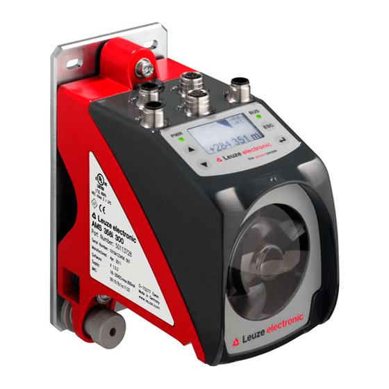
- Page 1 AMS 348i SSI Optical Laser Measurement System – PROFINET / SSI O r i g in a l op e r a ti n g i n s tr uc t i o ns...
- Page 2 © 2017 Leuze electronic GmbH + Co. KG In der Braike 1 D-73277 Owen / Germany Phone: +49 7021 573-0 Fax: +49 7021 573-199 http://www.leuze.com info@leuze.com Leuze electronic 348i...
- Page 3 348i Die Hauptmenüs Hauptmenü Geräteinformation AMS 348i 120 SSI Leuze electronic In diesem Menüpunkt erhalten Sie detaillierte Infor- mationen über GmbH & Co. KG • Gerätetyp, SW: V 1.3.0 HW:1 • Hersteller, SN: ----------------------- • Softwareversion und Hardwarestand, • Seriennummer.
-
Page 4: Table Of Contents
General specifications AMS 348i SSI ........ - Page 5 Table of contents Reflectors ......... . . 27 General information .
- Page 6 Table of contents Identification & Maintenance Functions ........55 PROFINET –...
- Page 7 Table of contents Type overview and accessories ......113 12.1 Type key ............. 113 12.2 Type overview AMS 348 SSI (PROFINET + SSI).
-
Page 8: General Information
Notice! The Declaration of Conformity for these devices can be requested from the manufacturer. The manufacturer of the product, Leuze electronic GmbH + Co. KG in D-73277 Owen, possesses a certified quality assurance system in accordance with ISO 9001. Leuze electronic... -
Page 9: Description Of Functions Ams 348 Ssi
With the AMS 3xxi product series, Leuze electronic makes available a range of internation- ally relevant interfaces. Note that each interface version listed below corresponds to a different AMS 3xxi model. -
Page 10: Safety
Leuze electronic GmbH + Co. KG is not liable for damages caused by improper use. Read the technical description before commissioning the device. Knowledge of this technical description is an element of proper use. -
Page 11: Foreseeable Misuse
The device must not be tampered with and must not be changed in any way. The device must not be opened. There are no user-serviceable parts inside. Repairs must only be performed by Leuze electronic GmbH + Co. KG. Competent persons Connection, mounting, commissioning and adjustment of the device must only be carried out by competent persons. -
Page 12: Disclaimer
Safety Disclaimer Leuze electronic GmbH + Co. KG is not liable in the following cases: • The device is not being used properly. • Reasonably foreseeable misuse is not taken into account. • Mounting and electrical connection are not properly performed. - Page 13 Affix the laser information and warning signs so that they are legible without exposing the reader to the laser radiation of the device or other optical radiation. A Laser aperture B Laser warning sign C Laser information sign with laser parameters Figure 2.1: Laser apertures, laser warning signs 348i Leuze electronic...
- Page 14 4 mW 4 mW Pulse duration: 18 μs 18 μs Wavelength: 655 nm 655 nm CLASS 2 LASER PRODUCT IEC 60825-1:2007 Complies with 21 CFR 1040.10 GB7247.1-2012 Figure 2.2: Laser warning and information signs – supplied stick-on labels Leuze electronic 348i...
-
Page 15: Fast Commissioning / Operating Principle
Further information can be found in chapter 5.2 and chapter 5.3. 3.1.2 Reflector mounting The reflector is mounted using 4 screws (M5). The reflector is angled using the spacer sleeves included. Incline the reflector by approx. 1°. Detailed information can be found in chapter 6.4. 348i Leuze electronic... -
Page 16: Connecting The Voltage Supply
• Download of the project to the connected Siemens control. Further information regarding the individual commissioning steps is provided in see chapter 9.8.4 "Configuration steps for a Siemens Simatic S7 control". Detailed information can be found in chapter 9. Leuze electronic 348i... -
Page 17: Specifications
SSI clock rate 50kHz … 800kHz Data format see chapter 10.4 Operating and display elements Keyboard 4 buttons Display monochromatic graphical display, 128 x 64 pixels 4 LEDs, 2 of which are used to display the PROFINET connection 348i Leuze electronic... - Page 18 This is a Class A product. In a domestic environment this product may cause radio interference, in which case the operator may be required to take adequate measures. The AMS 348i SSI is designed in accordance with safety class III for supply with PELV (protective extra-low voltage). Leuze electronic 348i...
-
Page 19: Dimensioned Drawing Ams 348I Ssi
4.1.2 Dimensioned drawing AMS 348i M5 screw for alignment Knurled nut with WAF4 hexagon socket and M5 nut for securing Optical axis Zero point of the distance to be measured Figure 4.1: Dimensioned drawing AMS 348 SSI 348i Leuze electronic... -
Page 20: Type Overview Ams 348I Ssi
120m operating range, PROFINET/SSI interface, integrated heating 50127224 AMS 348 200 H SSI 200m operating range, PROFINET/SSI interface, integrated heating 50127225 AMS 348 300 H SSI 300m operating range, PROFINET/SSI interface, integrated heating 50127226 Table 4.1: Type overview AMS 348 SSI Leuze electronic 348i... -
Page 21: Installation And Mounting
Device name plate using the AMS 358 as an example Notice! Please note that the shown name plate is for illustration purposes only; the contents do not correspond to the original. Save the original packaging for later storage or shipping. 348i Leuze electronic... -
Page 22: Mounting The Ams 348 Ssi
Installation and mounting If you have any questions concerning your shipment, please contact your supplier or your local Leuze electronic sales office. Observe the applicable local regulations when disposing of the packaging materials. Mounting the AMS 348i M5 screw for... - Page 23 WAF4 hexagon socket ("B" in figure 5.2). Knurled nut and nut must not be tightened until alignment has been completed. Attention! The device must not be opened. Failure to comply will render the guarantee void. Warranted features cannot be guaranteed after the device has been opened. 348i Leuze electronic...
-
Page 24: Optional Mounting Bracket
Optional mounting bracket A mounting bracket for mounting the AMS 348i SSI on a flat, horizontal surface is available as an optional accessory. Type designation: MW OMS/AMS 01 Part no.: 50107255 Laser beam Figure 5.3: Optional mounting bracket Leuze electronic 348i... -
Page 25: Parallel Mounting Of The Ams 348I Ssi
Both reflectors move in parallel at the same distance to the AMS 348i SSI. Measurement distance up to 120m: minimum parallel spacing X ≥ 600mm Measurement distance up to 200m: minimum parallel spacing X ≥ 750mm Measurement distance up to 300m: minimum parallel spacing X ≥ 750mm 348i Leuze electronic... -
Page 26: Parallel Mounting Of Ams 348I Ssi And Ddls Optical Data Transmission
SSI do not interfere with one another. Depending on the size of the used reflector, the DDLS can be mounted with a minimum parallel spacing of 100mm to the AMS 348i SSI. The parallel spacing is inde- pendent of the distance. Leuze electronic 348i... -
Page 27: Mounting The Ams 348 Ssi With Laser Beam Deflector Unit
Use the M5 screws to mount the deflector unit. Secure the screws with a toothed lock washer to protect against loosening caused by vibrations. Figure 5.5: Mounting variants of the US AMS 01 laser beam deflector unit 348i Leuze electronic... -
Page 28: Dimensioned Drawing Of Us Ams 01 Deflector Unit
Installation and mounting 5.3.2 Dimensioned drawing of US AMS 01 deflector unit Laser beam Figure 5.6: Dimensioned drawing of US AMS 01 deflector unit Leuze electronic 348i... -
Page 29: Mounting The Us 1 Oms Deflector Unit Without Mounting Bracket
Height of the spring in non- preloaded state A Mirror Figure 5.7: Photo and dimensioned drawing of the US 1 OMS deflector unit Alignment of the laser light spot on the reflector is performed as described in chapter 5.2. 348i Leuze electronic... -
Page 30: Reflectors
348i SSI, such as the operating range or accu- racy, can only be achieved with the reflective tape specified by Leuze electronic. The reflective tapes are available as adhesive tapes, affixed to a metal plate and with an integrated heater especially for use at low temperatures. Reflective tapes with heating have the designation "Reflective tape …x…-H", where "H"... -
Page 31: Specifications Of The Self-Adhesive Foil
Do not use any agents that act with a grinding effect. A conventional household Cleaning detergent can be used as a cleaning agent. Rinse with clear water and dry the surface. Storing the reflector Store in a cool and dry place. 348i Leuze electronic... -
Page 32: Dimensioned Drawing Of Reflective Tape On A Metal Plate
Dimensioned drawing of reflective tape on a metal plate Always align the TOP marking with the AMS connections! (Chapter 6.4.2) Figure 6.1: Dimensioned drawing of reflectors Part Reflective tape (mm) Reflector plate (mm) Reflective tape 200x200-M Reflective tape 500x500-M Reflective tape 914x914-M Leuze electronic 348i... -
Page 33: Specifications Of Heated Reflectors
Do not use any agents that act with a grinding effect. A conventional house- Cleaning hold detergent can be used as a cleaning agent. Rinse with clear water and dry the surface. Storing the reflector Store in a cool and dry place. 348i Leuze electronic... -
Page 34: Dimensioned Drawing Of Heated Reflectors
XL ± 1 L ± 0,5 XL ± 1 Si cable 3 x 0.75mm² Figure 6.2: Dimensioned drawing of heated reflectors Part Reflective tape (mm) Insulated base plate (mm) Reflective tape 200x200-H Reflective tape 500x500-H Reflective tape 914x914-H Leuze electronic 348i... -
Page 35: Selecting Reflector Sizes
Depending on system design, the reflector can be mounted so that it travels on the vehicle or it can be mounted at a fixed location. Attention! The reflector sizes shown below are a recommendation from Leuze electronic for on-vehicle mounting of the AMS 348i SSI. -
Page 36: Mounting The Reflector
For this purpose, use the alignment elements provided on the AMS 348i SSI… (see chapter 5.3 "Mounting the AMS 348i SSI with laser beam deflector unit"). If necessary, remove the protective foil from the reflector. Attention! The "TOP" label mounted on the reflectors should be aligned the same as the connections... - Page 37 Reflective tapes …-S and …-M Pitch approx. 1° Direct reflection from the triad structure Deflected surface reflection due to the pitch of the reflective tape Figure 6.3: Reflector mounting Pitch approx. 1° Spacer sleeves Figure 6.4: Pitch of the reflector 348i Leuze electronic...
- Page 38 Pitch approx. 1° Direct reflection from the triad structure Deflected surface reflection due to the pitch of the reflective tape Figure 6.5: Mounting of heated reflectors Pitch approx. 1° Spacer sleeves Figure 6.6: Pitch of the heated reflector Leuze electronic 348i...
-
Page 39: Table Of Reflector Pitches
Notice! Reliable function of the AMS 348i SSI and, thus, max. operating range and accuracy can only be achieved with the reflective tape specified by Leuze electronic. No function can be guaranteed if other reflectors are used! 348i Leuze electronic... -
Page 40: Electrical Connection
For UL applications, use is permitted exclusively in Class 2 circuits according to NEC (National Electric Code). The laser measurement systems are designed in accordance with safety class III for supply by PELV (protective extra-low voltage with reliable disconnection). Leuze electronic 348i... -
Page 41: Pwr - Voltage Supply / Switching Input/Output
BUS IN (4-pin socket, D-coded) BUS IN Name Remark Transmit Data + Receive Data + Transmit Data - TD+ 1 Receive Data - Thread Functional earth (housing) M12 socket (D-coded) Table 7.2: Pin assignments for BUS IN 348i Leuze electronic... -
Page 42: Profinet Bus Out
- Data line SSI (output) + Clock line SSI CLK+ CLK+ 3 DATA+ (input electrically insulated) - Clock line SSI CLK- (input electrically insulated) CLK- Functional earth M12 connector (B-coded) Thread Functional earth (housing) Table 7.4: SSI pin assignment Leuze electronic 348i... -
Page 43: Service
Transmission line RS 232/service data Voltage supply 0VDC RS232-RX Receiving line RS 232/service data Not used RS232-RX M12 socket Thread Functional earth (housing) (A-coded) Table 7.5: Service pin assignments Notice! The service interface is designed only for use by Leuze electronic! 348i Leuze electronic... -
Page 44: Display And Control Panel Ams 348 Ssi
Display and control panel AMS 348i SSI Display and control panel AMS 348i Structure of the control panel Status display Bus/interface info Bar graph Distance measurement value Control buttons Figure 8.1: Structure of the control panel using the AMS 304 PROFIBUS device variant as an example... - Page 45 Display and control panel AMS 348i SSI Warning - laser prefailure message: Laser diode old, device still functional, exchange or have repaired. Warning - temperature monitoring: Permissible internal device temperature exceeded / not met. Plausibility error: Implausible measurement value. Possible causes: light beam interruption, outside of measurement range, permissible internal device temperature considerably exceeded or traverse rate >10m/s.
-
Page 46: Led Status Displays
Display and control panel AMS 348i SSI Position value The measured position value is displayed in the configured unit of measurement. With the metric setting, the measurement value is always displayed in meters +87.000m with three decimal places. With the inch setting, the measurement value is always displayed in inches +87.0in... - Page 47 Display and control panel AMS 348i SSI Orange continuous light Power LED orange - Configuration via the display - No data on the host interface BUS LED BUS LED off - No supply voltage (Power) - No communication possible - PROFINET communication not initialized or inactive...
-
Page 48: Control Buttons
Display and control panel AMS 348i SSI LINK LED for BUS IN and BUS OUT A green/orange multicolor LED below the BUS IN and BUS OUT connectors indicates the EtherNet/PROFINET connection status. ACT0 LNK0 ACT1 LNK1 LINK LED for BUS IN... -
Page 49: Menu Description
Display and control panel AMS 348i SSI Setting values If input of a value is possible, the display looks like this: Delete character Enter digit <-|0123456789 save Default ----------------- unit Save Use the buttons to set the desired value. An accidental, incorrect entry can be corrected by selecting <-| and then pressing... - Page 50 Display and control panel AMS 348i SSI Status and measurement data - main menu LNK0 IO2 TMP LNK1 • Display of status-, warning-, and error messages. • Status overview of the switching inputs/outputs. • Bar graph for the reception level.
-
Page 51: Parameter Menu
Display and control panel AMS 348i SSI 8.3.2 Parameter menu Parameter handling submenu The following functions can be called up in the Parameter handling submenu: • Lock and enable parameter entry • Set up a password • Reset the AMS 348i SSI to default settings. - Page 52 Display and control panel AMS 348i SSI Table 8.3: SSI submenu Level 3 Level 4 Level 5 Selection/configuration option Standard Description Coding Binary/gray Gray Specifies the output format of the measurement value. Number of data 24-bit/25-bit/26-bit 24 bit bits The measurement value can be displayed on the SSI interface in this data width.
- Page 53 Display and control panel AMS 348i SSI Table 8.4: Position value submenu Level 3 Level 4 Level 5 Selection/configuration option Standard Description Preset The preset value is accepted by means of teach pulse. The teach pulse can be applied to a hardware input of the M12 PWR connector. The hard- ware input must be appropriately configured.
- Page 54 Display and control panel AMS 348i SSI Table 8.5: I/O submenu Level 3 Level 4 Level 5 Selection/configuration option Standard Description Limit value Value input in mm or inch/100 input Upper pos. Activation ON / OFF limit 2 Limit value...
-
Page 55: Language Selection Menu
Display and control panel AMS 348i SSI 8.3.3 Language selection menu Language selection o Deutsch English o Español o Français o Italiano There are 5 display languages available: • German • English • Spanish • French • Italian The AMS 348i SSI is delivered from the factory with the display preset to English. -
Page 56: Operation
Display and control panel AMS 348i SSI Operation Described here is an operating process using parameter enabling as an example. Parameter enabling During normal operation parameters can only be viewed. If parameters are to be changed, the ON menu item in the Parameter -> Parameter handling -> Parameter enable menu must be activated. - Page 57 Display and control panel AMS 348i SSI Attention! The AMS 348i is deactivated on the PROFINET if parameter enabling is activated via the dis- play. The device is reactivated on the PROFINET after parameter enabling is exited. Notice! PROFINET network,...
-
Page 58: Profinet Interface
PROFINET application profile number 0xF600 (Generic Device) Info about subchannels and submod- PROFILE_SPECIFIC_TYPE UNSIGNED16 0x01,0x01 ules. Not relevant IM_VERSION 2xUNSIGNED8 Implemented I&M version V 1.1 0x01,0x01 IM_SUPPORTED Bit[16] Optional I&M records available Table 9.1: Base record I&M0 Leuze electronic 348i... -
Page 59: Profinet - Star Topology
348i 348i 348i "myAMS 348i_1" "myAMS 348i_2" "myAMS 348i_3" Figure 9.2: PROFINET in a linear topology The maximum length of a segment (from the host to the furthest participant) is limited to 100m. 348i Leuze electronic... -
Page 60: Profinet - General Information On Wiring
PROFINET" on page 116. For unavailable cable lengths, you can configure your cables yourself. For this purpose, Leuze electronic offers a D-coded M12 round plug connector for Bus IN and Bus Out, see table 12.4.3 "Accessory M12 connector" on page 114. -
Page 61: Profinet - Electrical Connection
This prevents potential compensating currents over the shield and possible interference coupling by compensating currents. The signal lines must be stranded in pairs. Use CAT 5 cable for the connection. 348i Leuze electronic... -
Page 62: Profinet - Commissioning And Configuration
• Acyclic data exchange, and also for the transfer of various information types such - Parameters for the configuration of the modules during the establishment of the communication - I&M data (Identification & Maintenance functions) - Reading diagnostic information - Reading I/O data - Writing device data Leuze electronic 348i... -
Page 63: Measures To Be Performed Prior To The Initial Commissioning
Connecting functional earth FE Ensure that the functional earth (FE) is connected correctly. Unimpaired operation is only guaranteed when the functional earth is connected properly. All electrical disturbances (EMC couplings) are discharged via the functional earth connec- tion. 348i Leuze electronic... -
Page 64: Starting The Device
In the event of a connection interruption, the device behaves in the same way. The outputs are deactivated during device start-up. This section describes how the AMS 348i is configured in a Siemens Simatic S7 for PROFINET. Leuze electronic 348i... -
Page 65: Configuration Steps For A Siemens Simatic S7 Control
In the following, the terms "GSD" or "GSD file" always refer to the GSDML-based format. The GSDML file can support an arbitrary number of languages in one file. Every GSDML file contains a version of the AMS 348i device model. This is also reflected in the file name. 348i Leuze electronic... - Page 66 PROFINET, all parameters are set to default values. If these parameters are not changed by the user, the device functions with the default settings delivered by Leuze electronic. For the default settings of the AMS 348i, please refer to the following module descriptions.
- Page 67 MAC ID of the installed device and the device name assigned in offline mode during the further course of configuration, see also step 5. Figure 9.6: Assign unique device name in the properties window 348i Leuze electronic...
- Page 68 This figure is for illustration only and does not correspond in all details to the AMS 348i. The MAC ID in particular must be read separately from each individual device. The MAC ID is also shown in the display of the AMS 348i. Leuze electronic 348i...
- Page 69 Affix the “Address Link Label” in the documents, e.g., in the installation diagram, accor- ding to the position of the device. After successful naming, the device name can be read here under DEVName. Network information IP Address: ---.---.---.--- Net mask: ---.---.---.--- Gateway: ---.---.---.--- MAC ID: --.--.--.--.--.-- DevName: ------------------------- 348i Leuze electronic...
- Page 70 It is mandatory that the device name corresponds to the device name assigned in hardware configuration (step 3). Under "Target systems", select item "Edit Ethernet participant". Click "Search" to scan the connected PROFINET network for MAC addresses. Figure 9.9: Scan the PROFINET network for connected devices (MAC addresses) Leuze electronic 348i...
- Page 71 Please be sure to pay attention that the names are the same and that the installed device is correctly assigned to the hardware configuration. This is particularly important if identical devices are installed several times in the same system. 348i Leuze electronic...
-
Page 72: Profinet Gsd File
17 different modules. Each of these modules can only be activated once per AMS. The AMS 348i checks its max. permissible number of modules. The control also reports an error if the input and output data across all modules exceed a total length of 1024 bytes. Leuze electronic 348i... - Page 73 All input and output modules described in this documentation are described from the con- troller's perspective: Described inputs (I) are inputs of the control. Described outputs (O) are outputs of the control. Described parameters (P) are parameters of the GSD file in the control. 348i Leuze electronic...
-
Page 74: Overview Of The Gsd Modules
(P) Monitoring for over/under values (P) Monitoring direction dependent yes/no Velocity (P) Velocity limit value 1 page 89 Limit value 1 (P) Hysteresis of velocity limit value (P) Start of velocity monitoring range (P) End of velocity monitoring range Leuze electronic 348i... - Page 75 (P) Display language selection (P) Display illumination (P) Display contrast Other page 100 (P) Activate/inhibit password (P) Password (P) Heating control – – (P) Position resolution Free resolution page 101 (P) Velocity resolution Table 9.3: Overview of the GSD modules 348i Leuze electronic...
-
Page 76: Detail Description Of The Modules
The individual modules are numbered from 1 … 20. The parameters and input/output data within a module are from … Example: preset parameter in module 2 becomes active only when the preset teach occurs via module 2 , 4 or 5 . Leuze electronic 348i... - Page 77 32 bit Offset The resolution of the offset value is inde- pendent of the resolution selected in module 1. The entered offset applies immediately without any further release. Parameter length: 6 bytes see following notice! 348i Leuze electronic...
- Page 78 Description Rel. Data Value Default Unit CR to addr. type module Metr. Inch sign Output of the current position. -999999 … +999999 – scaled 32 bit Position value Input data length: 4 bytes consistently Output data None Leuze electronic 348i...
- Page 79 Default Unit CR to addr. type module Metr. Inch Read in the preset value. 01 Preset teach – – Preset teach Preset value is deactivated. 01 Preset teach – – Preset reset Output data length: 1 byte 348i Leuze electronic...
- Page 80 The value is accepted during a corre- sponding teach event. sign The resolution of the preset value is -999999 … +999999 – in/100 32 bit Preset independent of the resolution selected in module 1. Output data length: 5 bytes Leuze electronic 348i...
- Page 81 1 = ON set. 0 = OFF Laser (LSR) – Laser prefailure message. 1 = ON Plausibility (PLB) 0 = OFF If implausible measurement values are – diagnosed, the output is set. 1 = ON 348i Leuze electronic...
- Page 82 0: Output at signal level not The output can be activated/deactivated active with this bit. The corresponding release – – is performed in module 4, output param- State 1: Output at signal level eter bit 2.0. active Output data length: 1 byte Leuze electronic 348i...
- Page 83 1 = ON set. 0 = OFF Laser (LSR) – Laser prefailure message. 1 = ON Plausibility (PLB) 0 = OFF If implausible measurement values are – diagnosed, the output is set. 1 = ON 348i Leuze electronic...
- Page 84 0: Output at signal level not The output can be activated/deactivated active with this bit. The corresponding release – – is performed in module 5, output param- State 1: Output at signal level eter bit 2.1. active Output data length: 1 byte Leuze electronic 348i...
- Page 85 1. tion limit 1: Value less than limit value 1 0: OK Upper posi- Signals that the value is greater than – – – tion limit upper limit value 1. 1: Value greater than limit value 1 348i Leuze electronic...
- Page 86 Input data length: 2 bytes Output data Output data Description Rel. Data Value Default Unit CR to addr. type module Metr. Inch 0: Laser ON Laser control. – – – Laser 1: Laser OFF Output data length: 2 bytes Leuze electronic 348i...
- Page 87 -999999 … +999999 in/100 – Lower pos. 32 bit limit 1 sign Specifies the upper position limit. 4…7 -999999 … +999999 in/100 – Upper pos. 32 bit limit 1 Parameter length: 8 bytes Input data None Output data None 348i Leuze electronic...
- Page 88 -999999 … +999999 in/100 – Lower pos. 32 bit limit 2 sign Specifies the upper position limit. 4…7 -999999 … +999999 in/100 – Upper pos. 32 bit limit 2 Parameter length: 8 bytes Input data None Output data None Leuze electronic 348i...
- Page 89 – – Specifies whether the PLB status bit is 0: OFF set immediately in the event of an error Suppress – – velocity sta- or if it is suppressed for the configured 1: ON velocity suppression time. 348i Leuze electronic...
- Page 90 SSI, negative velocities are output. If the "negative" count direction is configured in module 1, the velocity signs are reversed. Measurement value preparation averages all velocity values calculated during the selected period (averaging) to yield a velocity output value. Leuze electronic 348i...
- Page 91 Input data Input data Description Rel. Data Value Default Unit CR to addr. type module Metr. Inch sign Current velocity. -999999 … +999999 scaled – 32 bit Velocity Input data length: 4 bytes consistently Output data None 348i Leuze electronic...
- Page 92 Limit value is compared to the current unsign (in/100) 1…2 0 … 20000 mm/s Velocity limit velocity. 16 bit value 1 Relative shift to prevent signal bounc- unsign (in/100) Velocity 3…4 0 … 20000 mm/s – ing. 16 bit hysteresis 1 Leuze electronic 348i...
- Page 93 32 bit range start The velocity limit value is monitored up sign … -999999 … +999999 in/100 – Limit value 1 to this position. 32 bit range end Parameter length: 13 bytes Input data None Output data None 348i Leuze electronic...
- Page 94 32 bit range start The velocity limit value is monitored up sign … -999999 … +999999 in/100 – Limit value 2 to this position. 32 bit range end Parameter length: 13 bytes Input data None Output data None Leuze electronic 348i...
- Page 95 32 bit range start The velocity limit value is monitored up sign Limit value 3 … -999999 … +999999 in/100 – to this position. 32 bit range end Parameter length: 13 bytes Input data None Output data None 348i Leuze electronic...
- Page 96 32 bit range start The velocity limit value is monitored up sign Limit value 4 … -999999 … +999999 in/100 – to this position. 32 bit range end Parameter length: 13 bytes Input data None Output data None Leuze electronic 348i...
- Page 97 32 bit range start The velocity limit value is monitored up sign … -999999 … +999999 in/100 – Limit value to this position. 32 bit range end Output data length: 13 bytes consistently 348i Leuze electronic...
- Page 98 1: Limit value violated value status 0: Comparison not active Signals whether the current velocity is Velocity com- – – – parison compared with this limit value. 1: Comparison active Limit value 1 Leuze electronic 348i...
- Page 99 1: Comparison active Limit value 4 0: Comparison not active Signals whether the current velocity is Dynamic – – – compared with this limit value. velocity com- 1: Comparison active parison Input data length: 2 bytes Output data None 348i Leuze electronic...
- Page 100 If the SSI interface is not configured via module 17 (SSI interface) in PROFINET oper- ation, the SSI interface is operated with the default parameters. If the SSI interface is operated without PROFINET (PROFINET OFF/SSI ON), configuration is performed via the display. Leuze electronic 348i...
- Page 101 0: OFF Laser (LSR) 1: Error – – Laser prefailure message. 1: ON 0: OFF Plausibility (PLB) – – Plausibility error. 1: ON 0: OFF Hardware (ERR) – – Hardware error. 1: ON Parameter length: 2 bytes 348i Leuze electronic...
- Page 102 25-bit; resolution 0.001 335in ≈ 26-bit; resolution 0.1 6,710m 67,108in 1,704m ≈ 26-bit; resolution 0.01 671m 6,710in 170m ≈ 26-bit; resolution 0.001 671in Figure 9.18: SSI interface - resolution and maximum position value which can be represented Leuze electronic 348i...
- Page 103 < 30°C: heating on amb. This parameter is available as stan- > 35°C: heating off amb. dard, but functions only for devices with integrated heating (AMS 348 SSI… H). Parameter length: 4 bytes Input data None Output data None 348i Leuze electronic...
- Page 104 Due to the free resolution in the exam- ple, an internal measurement value of 3333mm gives an output value of “1111”. The resolution of the “Offset", "Preset" and "Limit values" parameters is not affected by free resolution. Parameter length: 4 bytes Leuze electronic 348i...
-
Page 105: Ssi
The SSI interface can only represent positive distance values. If negative output values are ascertained due to the offset or count direction, a zero value is output at the SSI interface! In the event of a number overflow, all data bits are set to "1". 348i Leuze electronic... -
Page 106: Ssi Sequence Diagram
The data can be read out with a clock rate between 80kHz and 800kHz. Attention! Updating the measurement values on the SSI interface of the AMS 348i SSI: The measurement value on the SSI interface of the AMS 348i SSI is updated every 1.7ms independent of the clock frequency. Leuze electronic 348i... -
Page 107: Cable Length As A Function Of The Data Rate
- Clock line SSI (input electrically insulated) Functional earth Thread Functional earth (housing) Figure 10.2: SSI - electrical connection Notice! To connect the SSI interface we recommend our ready-made SSI cables, see "Order codes for SSI connection cables" on page 119. 348i Leuze electronic... -
Page 108: General Information To The Ams 348 Ssi Parameters
Error handling procedures Position output: 0 Suppress position status: active Position suppression time: 100ms Display language English Display illumination OFF after 10min. Display contrast Medium Password protection Password 0000 Table 10.2: Default settings of the SSI interface Leuze electronic 348i... -
Page 109: Changing The Ssi Settings Via The Display
For basic operation of the display please refer to chapter 8.2.3. In order to change the parameters please activate parameter enabling. The SSI interface remains active even during parameter enabling. Changes to parameters have an immediate effect. 348i Leuze electronic... -
Page 110: Diagnostics And Troubleshooting
Only diagnostics or process alarms actually trigger the transmission of an alarm. All other types (preventative maintenance and status messages) only lead to an entry into the diag- nostics buffer and are thus part of the state-based diagnostics. Table 11.1: AMS 348 alarm and diagnostics messages Leuze electronic 348i... -
Page 111: Service And Diagnostics In The Display Of The Ams 348 Ssi
(always "1", since no summation occurs) The status messages within the ring memory are selected with the up/down buttons The enter button can be used to call up detailed information on the corresponding status messages with the following details: 348i Leuze electronic... -
Page 112: Diagnostics
Leuze for internal evaluation. The diagnostics have no influence on the communication to the host interface and can be activated during operation of the AMS 348i SSI. 11.1.3 Expanded diagnostics The Expanded diagnostics menu item is used for Leuze-internal evaluation. Leuze electronic 348i... -
Page 113: General Causes Of Errors
Light beam interruption Check alignment. PWR-LED "flashes red" Plausibility error Traverse rate >10m/s. Hardware error For error description, see display, PWR-LED "static red" It may be necessary to send in the device. Table 11.2: General causes of errors 348i Leuze electronic... -
Page 114: Interface Errors
Restrict traversing path or select AMS with larger (implausible measurement exceeded measurement range. values) Velocity greater than 10m/s Reduce velocity. Ambient temperature far outside of the permissible Select AMS with heating or ensure cooling. range (TMP display; PLB) Leuze electronic 348i... -
Page 115: Device Type
Customer data (please complete) Device type: Company: Contact partner / department: Phone (direct): Fax: Street / No: ZIP code/City: Country: Leuze Service fax number: +49 7021 573 - 199 348i Leuze electronic... -
Page 116: Type Overview And Accessories
120m operating range, PROFINET/SSI interface, integrated heating 50127224 AMS 348 200 H SSI 200m operating range, PROFINET/SSI interface, integrated heating 50127225 AMS 348 300 H SSI 300m operating range, PROFINET/SSI interface, integrated heating 50127226 Table 12.1: Type overview AMS 348 SSI Leuze electronic 348i... -
Page 117: Overview Of Reflector Types
KDS ET M12/RJ45 W - 4P Converter from M12 D-coded to RJ45 socket 50109832 KD 02-5-BA M12 connector, B-coded socket, SSI 50038538 KD 02-5-SA M12 connector, B-coded plug 50038537 KD 095-5A M12 connector, A-coded socket, Power (PWR) 50020501 Table 12.5: Accessory M12 connector 348i Leuze electronic... -
Page 118: Accessory Ready-Made Cables For Voltage Supply
Order codes of the cables for voltage supply Type designation Description Part no. KD U-M12-5A-V1-050 M12 socket, A-coded, axial plug outlet, open cable end, 50132079 cable length 5m KD U-M12-5A-V1-100 M12 socket, A-coded, axial plug outlet, open cable end, 50132080 cable length 10m Leuze electronic 348i... -
Page 119: Accessory Ready-Made Cables For Profinet
This prevents potential compensating currents over the shield and possible interference coupling by compensating currents. The signal lines must be stranded in pairs. Use CAT 5 cable for the connection. 348i Leuze electronic... - Page 120 Cable length 2m, cable 1:1, not crossed 50137077 KSS ET-M12-4A-M12-4A-P7-050 Cable length 5m, cable 1:1, not crossed 50137078 KSS ET-M12-4A-M12-4A-P7-100 Cable length 10m, cable 1:1, not crossed 50137079 KSS ET-M12-4A-M12-4A-P7-150 Cable length 15m, cable 1:1, not crossed 50137080 Leuze electronic 348i...
-
Page 121: Accessory Ready-Made Cables For Ssi
Specifications of the SSI connection cable Operating temperature range in rest state: -40°C … +80°C in motion: -5°C … +80°C Material the cables are free of halogens, silicone and PVC Bending radius > 80mm, suitable for drag chains 348i Leuze electronic... - Page 122 20m KB SSI/IBS-25000-BA M12 socket, B-coded, for SSI/Interbus, axial connector, 50108447 open cable end, cable length 25m KB SSI/IBS-30000-BA M12 socket, B-coded, for SSI/Interbus, axial connector, 50108446 open cable end, cable length 30m Leuze electronic 348i...
-
Page 123: Maintenance
Contact your Leuze distributor or service organization should repairs be required. The addresses can be found on the inside of the cover and on the back. Notice! When sending the laser measurement systems to Leuze electronic for repair, please provide an accurate description of the error. 13.3... - Page 124 Display ......41 Contrast ......100 Leuze electronic 348i...
- Page 125 PWR LED ......43 Quality assurance ......5 348i Leuze electronic...
- Page 126 Velocity measurement error ....95 Velocity resolution ..... . . 88 Leuze electronic 348i...
- Page 127 Index Waving of the participant ....68 348i Leuze electronic...
- Page 128 Menüstruktur AMS 348i Ebene 1 Ebene 2 Ebene 3 Ebene 4 Ebene 5 Auswahloption / Einstellmöglichkeit Detailinfos ab : Auswahl : Auswahl : Auswahl : Auswahl : Auswahl : Auswahl : Zurück : Zurück : Zurück : Zurück : Aktivieren : Zurück Geräteinformation Seite 46...
- Page 129 Menüstruktur AMS 348i Grenzwerte Obere Pos. Grenze 1 Aktivierung ON/OFF Grenzwerteingabe Werteeingabe in mm bzw. Inch/100 Untere Pos. Grenze 1 Aktivierung ON/OFF Grenzwerteingabe Werteeingabe in mm bzw. Inch/100 Obere Pos. Grenze 2 Aktivierung ON/OFF Grenzwerteingabe Werteeingabe in mm bzw. Inch/100 Untere Pos.
Need help?
Do you have a question about the AMS 348i SSI and is the answer not in the manual?
Questions and answers