
Subscribe to Our Youtube Channel
Related Manuals for Leuze electronic ASM1 Series


Summary of Contents for Leuze electronic ASM1 Series
- Page 1 ASM1, ASM1E, ASM2E AS-i Safety Monitor Buy: www.ValinOnline.com | Phone 844-385-3099 | Email: CustomerService@valin.com...
- Page 2 Safety and warning notices are labelled with the symbol. Leuze electronic GmbH + Co. KG is not liable for dam- ages caused by improper use. Knowledge of these instructions is an element of proper use. © Reprinting and duplication, including excerpts, are permis- sible only with the express approval of: Leuze electronic GmbH + Co.
- Page 3 The AS-i safety monitor is only suitable for use in electrical operating rooms / switch cabinets with minimum protection class IP54. The connection, commissioning and replacement of the AS-i safety monitor requires knowledge of the connecting and operating instructions as well as of the user manual for the asimon configuration and diagnostics software (see accesso- ries order guide).
-
Page 4: Range Of Application
Range of application Monitoring of safe AS-i slaves (e.g. emergency-shutdown switches) within an AS-i system as assigned with the ASiMon configuration software. Depending on the device variant, the second OSSD is available as safe AS-i output with or without relay. For full system expansion in protective operation, safe shutdown with a response time of maximum 40 ms. -
Page 5: Dimensioned Drawing
Dimensioned drawing 28,8 Buy: www.ValinOnline.com | Phone 844-385-3099 | Email: CustomerService@valin.com... -
Page 6: Specifications
Specifications Electrical data Operating voltage U 24V DC +/- 15% Residual ripple < 15% Rated operating current ASM1/1 and ASM1E/1: 150mA ASM1/2, ASM1E/2 and ASM2/1: 200mA ASM2E/2: 250mA Peak switch-on current All types: 600mA Reaction time < 40ms (safety-relevant) Delay before start-up <... - Page 7 Configuration interface RS 232 9600 baud, no parity, 1 start bit, 1 stop bit, 8 data bits Inputs and outputs "Start" input Optical coupling input (high active), input current approx. 10mA at 24V DC Input of "external device Optical coupling input (high active), monitoring circuit"...
- Page 8 Attention! Be certain to maintain the specified safeguards; only in this way is safe shutdown ensured in the case of failure. Attention! In addition to the system reaction time of max. 40ms, the reaction times of the safe AS-interface sensor slave, of the sensor being used for monitoring, of the safe AS-interface actuator slave and of the actuator used for this purpose must still be added.
-
Page 9: Electrical Installation
Electrical installation Attention! Electrical installation may only be performed by trained specialist technicians. Attention! Each safe AS-interface slave is to be activated at least once per year and the switching behaviour of the output circuits of the AS-interface safety monitor visually inspected. After replacing a safe AS-i slave, the new slave must be checked for proper function;... - Page 10 LED indicators ASM Colour Meaning AS-i 1 no supply green, continuous AS-interface supply present AS-i 2 normal operation red, continuous communication error AS-iS 1 no supply green, continuous AS-interface supply present AS-iS 2 normal operation red, continuous communication error 1 READY –...
- Page 11 not used LED AS-i 1 LED AS-i 1 (safe AS-i output) LED AS-i 2 LED AS-i 2 (safe AS-i output) Output circuit 2 Output circuit 1 Fig. 4.0-1: LED indicators in the device Terminal assignments of AS-i safety monitors ASM1/1 and ASM1E/1 Terminal Signal / description Electrical connection...
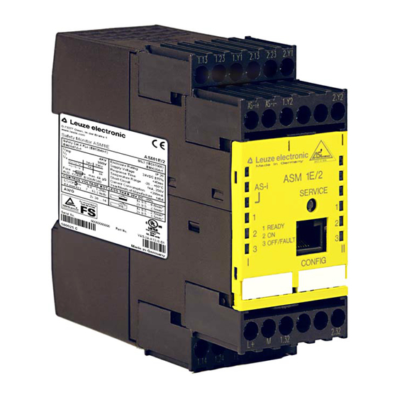
- Page 12 Terminal assignments of AS-i safety monitors ASM1/2 and ASM1E/2 Terminal Signal / description Electrical connection AS-i+ Connection to the AS-interface AS-i– +24V DC / supply voltage GND / reference ground Functional earth 1.Y1 EDM 1 / input of external de- vice monitoring circuit, output circuit 1 1.Y2...
- Page 13 Terminal assignments of AS-i safety monitors ASM2E/1 and ASM2E/2 Terminal Signal / description Electrical connection AS-i+ Connection to the AS-interface AS-i– AS-iS+ Safe AS-interface output for actuator monitoring or coupling AS-iS– of another AS-interface net- work +24V DC / supply voltage GND / reference ground Functional earth 1.Y1...
- Page 14 1) Safeguard according to technical data AS-i+ AS-i- Fig. 4.0-2: Connection for actuator monitoring AS-i network 1 AS-interface+ (brown) AS-interface- (blue) Coupled AS-i network 2 AS-interface+ (brown) AS-interface- (blue) Fig. 4.0-3: Coupling for AS-i networks Buy: www.ValinOnline.com | Phone 844-385-3099 | Email: CustomerService@valin.com...
- Page 15 Mounting The safety monitor is mounted by clipping onto a standard 35 mm rail acc. to EN 50022. ➢ To remove, firmly press the monitor against the upper rail guide and lift out. A, B, C, D: Fig. 5.0-1: Mounting the safety monitor ➢...
- Page 16 1. U = 0 V 2. a, b, c, d Fig. 5.0-2: Removing and mounting encoded connection terminals ➢ Mount cap and seal in steps 1-5. Buy: www.ValinOnline.com | Phone 844-385-3099 | Email: CustomerService@valin.com...
- Page 17 a = Sealable cap for safeguarding against unauthorised adjustment and for ESD protection (part of the delivery contents). Fig. 5.0-3: Mounting and sealing the cap For further information, see the connecting and operating instructions for the AS-i safety monitor. Buy: www.ValinOnline.com | Phone 844-385-3099 | Email: CustomerService@valin.com...
- Page 18 Replacing an AS-i safety monitor ✘ 24 V DC 24 V DC 24 V DC 1 Disconnect the defective (a) AS-i 2 Connect the defective (a) and the safety monitor from the supply and new (b) AS-i safety monitor via the connect the new monitor (b).
-
Page 19: Order Guides
Order guides Part No. Article Description 580020 ASM1/1 AS-i safety monitor, 1 OSSD 580021 ASM1/2 AS-i safety monitor, 2 OSSDs 580024 ASM1E/1 AS-i safety monitor, 1 OSSD; expanded functionality 580025 ASM1E/2 AS-i safety monitor, 2 OSSDs; expanded functionality 580028 ASM2E/1 AS-i safety monitor, 1 OSSD, 1 safe AS-i output, expanded functionality 580029... - Page 20 Order guides Accessories Part No. Article Description 580032 ASM-SWC ASM commissioning set for ASM1, ASM1E and ASM2E Contains: asimon configuration and diagnostics software, connecting and operating instructions, user manual for the software on CD, configuration cable, device-replacement data cable 50104078 ASM1-PK ASM1 configuration cable 50104079...
Need help?
Do you have a question about the ASM1 Series and is the answer not in the manual?
Questions and answers