Download Print this page
Atmel QTouch Application Note

Atmel QTouch Application Note

Schematic and layout checklist

Advertisement

Quick Links

APPLICATION NOTE
AT02259: QTouch Schematic and Layout Checklist
Atmel QTouch
Introduction
Designing a capacitive touch interface is an involved process that requires myriad
factors to be considered. These interfaces frequently need to co-exist with other
complex systems, which may affect its performance.
®
Since there are several considerations to be made while designing Atmel
®
QTouch
solutions it is important to know these for overall improvement of the
design. The purpose of this document is to provide a checklist that can be used to
review the schematic and PCB layout of these designs. This includes separate
checklists for designs using Atmel QTouch, QTouchADC and QMatrix. This
document only highlights the most important aspects and should not be
considered as a substitute for
QTAN0079 Buttons, Sliders and Wheels – Sensor
Design
Guide.
Features
Checklist for reviewing Atmel QTouch schematics and PCB layouts
Atmel-42094C-QTouch-Schematic-and-Layout-Checklist-ApplicationNote_072014

Advertisement

loading

Summary of Contents for Atmel QTouch

  • Page 1 These interfaces frequently need to co-exist with other complex systems, which may affect its performance. ® Since there are several considerations to be made while designing Atmel ® QTouch solutions it is important to know these for overall improvement of the design.
  • Page 2: Abbreviations And Definitions

    Slider: It is a one dimensional sensor used to implement linear position sensors. A group of channels • forms a Slider, which is used to detect the linear position of touch. A QTouch Slider is composed of three channels. A QMatrix Slider can be composed of three to eight channels •...
  • Page 3 Schematic Review This chapter consists of the checklists used for reviewing the schematics of Atmel QTouch, QTouchADC and QMatrix implementations. There are sections corresponding to each individual technology. Section 2.4 General is applicable to all technologies. Atmel QTouch This section consists of the checklist for reviewing a QTouch schematic.
  • Page 4 In Intra-Port connection, sense pins selected should be in incremental order as channel number of the sensor. Always SNS pin should be the lower numbered pin, in a channel. Figure 2-3. Pin Selection for Intra-Port Design QTouch Schematic and Layout Checklist [APPLICATION NOTE] Atmel-42094C-QTouch-Schematic-and-Layout-Checklist-ApplicationNote_072014...
  • Page 5 • Slider/Wheel uses only three channels A QTouch Slider/Wheel always uses only three channels. It is important to use channels with similar sensitivity. Using mismatched channels with significantly different sensitivities will lead to an unbalanced Slider/Wheel. Always split third channel (highest numbered channel) in a QTouch Slider.
  • Page 6 QTouch Library Selection Guide and the device datasheet. The AIN0 pin needs to be grounded. The AIN0 pin is not user configurable. QTouch Schematic and Layout Checklist [APPLICATION NOTE] Atmel-42094C-QTouch-Schematic-and-Layout-Checklist-ApplicationNote_072014...
  • Page 7 Rsmp can be any value within the range of 220kΩ to 1MΩ. This value is used to tune the sensitivity of the channels sharing the corresponding Y-line. Typically a 470kΩ resistor is used. QTouch Schematic and Layout Checklist [APPLICATION NOTE] Atmel-42094C-QTouch-Schematic-and-Layout-Checklist-ApplicationNote_072014...
  • Page 8 Total resistance between channels is 2kΩ to 10kΩ. The resistance between segments will depend on the number of segments used. There are no end resistors or split channels for a QMatrix Slider. Figure 2-6. Resistive Interpolated QMatrix Slider and Wheel QTouch Schematic and Layout Checklist [APPLICATION NOTE] Atmel-42094C-QTouch-Schematic-and-Layout-Checklist-ApplicationNote_072014...
  • Page 9 • Dedicated voltage regulator is used It is recommended to use a dedicated voltage regulator for a QTouch application. If the voltage regulator is shared with other components it is important to ensure that the power supply is clean. The ripple on the supply voltage needs to be within ±10mV.
  • Page 10 If there is any load on a discrete out pin of the microcontroller, ensure that the load does not sink or source too much current directly from chip. This can cause ground bounce which would in turn affect QTouch measurements. Typically the current should be limited to ~1mA, but this can vary depending on the part and sensitivity of channels.
  • Page 11 LED series resistor to minimize the impact. • Use multiple grounds in case of isolated sensors When sensor board is isolated from touch MCU board, prefer using multiple ground pins in the connector for effective return path. QTouch Schematic and Layout Checklist [APPLICATION NOTE] Atmel-42094C-QTouch-Schematic-and-Layout-Checklist-ApplicationNote_072014...
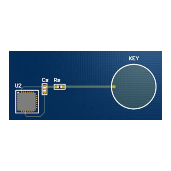
  • Page 12 Sense components are placed close to microcontroller pins The sense components (Cs and Rs for QTouch; only Rs for QTouchADC) should be placed close to the microcontroller sense pins. If they are placed too far from the pin, there will be increased noise pick-up from nearby sources.
  • Page 13 If Sense Lines are placed close to each other, it can cause cross-bleed and increase noise on the channels. It will also load both channels and decrease their sensitivity. Figure 3-3. Spacing Between Two Sense Lines QTouch Schematic and Layout Checklist [APPLICATION NOTE] Atmel-42094C-QTouch-Schematic-and-Layout-Checklist-ApplicationNote_072014...
  • Page 14 Typical QTouch Button Layout • Sense Lines are as short as possible Having long Sense Lines will worsen any loading and interference from nearby tracks and components. Sense Lines should not be longer than 150mm. QTouch Schematic and Layout Checklist [APPLICATION NOTE] Atmel-42094C-QTouch-Schematic-and-Layout-Checklist-ApplicationNote_072014...
  • Page 15 Meshed Ground to Provide Shielding from Noise Sources Behind the Board 3.1.4 QTouch Slider or Wheel The checklist in this section is applicable only to QTouch designs. • Small Slider/Wheel has a segment size of 6mm to 8mm Segment size should be comparable to the diameter of a standard finger touch. Segments that are too large will lead to poor linearity.
  • Page 16 • The first and last segments of the Slider are connected to the same channel This needs to be ensured for both spatially and resistively interpolated QTouch Sliders. The track connecting end segments is placed away from the Slider •...
  • Page 17 In a medium/large spatially interpolated Wheel the width of each interleaving ring is 5mm to 8mm • For increasing the diameter of the Wheel increase the number of interleaving rings rather than increasing the width of the ring. QTouch Schematic and Layout Checklist [APPLICATION NOTE] Atmel-42094C-QTouch-Schematic-and-Layout-Checklist-ApplicationNote_072014...
  • Page 18 Sensors • There are no ground planes directly under co-planar Buttons These will load the sensor and decrease the sensitivity. But the effect is not as dramatic as in the case of QTouch Sensors. • Y Electrodes are located on the top layer The Y electrodes should be located on the layer closest to touch in order to maximize the sensitivity.
  • Page 19 X-Y Separation and Front Panel Thickness Double Layer Flooded-X Electrode Layout Single Layer Planar Electrode Layout (the field only extends towards touch) Small X-Y separation = Thin Panel Large X-Y Separation = Thicker Panel QTouch Schematic and Layout Checklist [APPLICATION NOTE] Atmel-42094C-QTouch-Schematic-and-Layout-Checklist-ApplicationNote_072014...
  • Page 20 If absolutely necessary the Y Lines and GND track should cross at 90° on separate layers. Y Lines and GND tracks running parallel to each other for long distances should absolutely be avoided. QTouch Schematic and Layout Checklist [APPLICATION NOTE] Atmel-42094C-QTouch-Schematic-and-Layout-Checklist-ApplicationNote_072014...
  • Page 21 Spacing between adjacent Y Lines is at least T/2 If Y Lines are placed close to each other, it can cause cross-bleed and increase noise on the channels. It will also load both Y Lines and decrease their sensitivity. QTouch Schematic and Layout Checklist [APPLICATION NOTE] Atmel-42094C-QTouch-Schematic-and-Layout-Checklist-ApplicationNote_072014...
  • Page 22 When using Flex cables for interconnection of sense lines, group all X lines together and group Y lines together, and then use a ground trace in between the groups. This avoids formation of stray capacitance across the closely routed X and Y line. QTouch Schematic and Layout Checklist [APPLICATION NOTE] Atmel-42094C-QTouch-Schematic-and-Layout-Checklist-ApplicationNote_072014...
  • Page 23 In two layer Slider/Wheel the gap between Y Electrode traces is less than 4mm Gaps that are larger than 4mm can lead to an insensitive region on the Slider/Wheel. Figure 3-22. Two Layer QMatrix Slider/Wheel QTouch Schematic and Layout Checklist [APPLICATION NOTE] Atmel-42094C-QTouch-Schematic-and-Layout-Checklist-ApplicationNote_072014...
  • Page 24 Sensor electrode need to be made larger for proximity designs. Avoid ground traces/flood nearby or beneath the touch sensor to overcome loading effects and to have better sensitivity. For more details on proximity sensor design, refer to the application note “QTAN0087: Proximity Design Guide”. QTouch Schematic and Layout Checklist [APPLICATION NOTE] Atmel-42094C-QTouch-Schematic-and-Layout-Checklist-ApplicationNote_072014...
  • Page 25 Atmel QTouch Library User Guide http://www.atmel.com/Images/doc8207.pdf AVR3000: QTouch Conducted Immunity http://www.atmel.com/Images/doc8425.pdf QTAN0087: Proximity Design Guide http://www.atmel.com/Images/doc10760.pdf QTAN0062: QTouch and QMatrix Sensitivity Tuning for Keys, Sliders and Wheels http://www.atmel.com/Images/QTAN0062.pdf AVR042: AVR Hardware Design Considerations http://www.atmel.com/images/atmel-2521-avr-hardware-design-considerations_application-note_avr042. QTouch Schematic and Layout Checklist [APPLICATION NOTE] Atmel-42094C-QTouch-Schematic-and-Layout-Checklist-ApplicationNote_072014...
  • Page 26: Revision History

    Revision History Doc Rev. Date Comments 1. Changed to latest template. 2. Additional Schematic checklist items added under Atmel QTouch: • Sense pin selection for Inter-Port / Intra-Port design • Multiplexing sense line with programming line 3. Additional Schematic checklist items added under Atmel QMatrix: •...
  • Page 27 DISCLAIMER: The information in this document is provided in connection with Atmel products. No license, express or implied, by estoppel or otherwise, to any intellectual property right is granted by this document or in connection with the sale of Atmel products. EXCEPT AS SET FORTH IN THE ATMEL TERMS AND CONDITIONS OF SALES LOCATED ON THE ATMEL WEBSITE, ATMEL ASSUMES NO LIABILITY WHATSOEVER AND DISCLAIMS ANY EXPRESS, IMPLIED OR STATUTORY WARRANTY RELATING TO ITS PRODUCTS INCLUDING, BUT NOT LIMITED TO, THE IMPLIED WARRANTY OF MERCHANTABILITY, FITNESS FOR A PARTICULAR PURPOSE, OR NON-INFRINGEMENT.

This manual is also suitable for:

QtouchadcQmatrix