Table of Contents
Advertisement
Advertisement
Chapters
Table of Contents

Subscribe to Our Youtube Channel
Related Manuals for R&S FPC Series


Summary of Contents for R&S FPC Series
- Page 1 ® R&S Spectrum Analyzer User Manual (;ÜYN2) 1178413002...
- Page 2 ® This document describes the following R&S FPC models and options: ● ® R&S FPC1000 (1328.6660.02) ● ® R&S FPC1500 (1328.6660.03) ● ® R&S FPC-B22 Preamplifier (1328.6690.02) ● ® R&S FPC-B200 Wi-Fi Support (1328.6990.02) ● ® R&S FPC-K7 AM, FM, ASK, FSK demodulation (1328.6748.02) ●...
- Page 3 Safety Instructions Instrucciones de seguridad Sicherheitshinweise Consignes de sécurité Risk of injury and instrument damage The instrument must be used in an appropriate manner to prevent personal injury or instrument damage. ● Do not open the instrument casing. ● Read and observe the "Basic Safety Instructions" delivered as printed brochure with the instrument.
- Page 4 Gefahr von Verletzungen und Schäden am Gerät Betreiben Sie das Gerät immer ordnungsgemäß, um elektrischen Schlag, Brand, Verletzungen von Personen oder Geräteschäden zu verhindern. ● Öffnen Sie das Gerätegehäuse nicht. ● Lesen und beachten Sie die "Grundlegenden Sicherheitshinweise", die als gedruckte Broschüre dem Gerät beiliegen. ●...
- Page 5 Customer Support Technical support – where and when you need it For quick, expert help with any Rohde & Schwarz equipment, contact one of our Customer Support Centers. A team of highly qualified engineers provides telephone support and will work with you to find a solution to your query on any aspect of the operation, programming or applications of Rohde &...
-
Page 6: Table Of Contents
® Contents R&S Contents 1 Documentation Overview..............7 2 Regulatory Information................9 3 Preparing for Use................. 10 Unpacking and Checking the Instrument..............11 Placing or Mounting the Instrument................12 Connecting AC Power....................13 Turning the R&S FPC on and off................13 4 Instrument Tour..................15 Front Panel........................ - Page 7 ® Contents R&S 13 Measurement Wizard................59 14 The Spectrum Application..............66 14.1 Configuration Overview....................66 14.2 Measurements and Result Displays................68 14.3 Frequency Configuration................... 93 14.4 Amplitude Configuration.................... 98 14.5 Bandwidth Configuration..................106 14.6 Sweep Configuration....................109 14.7 Trigger Configuration....................112 14.8 Trace Configuration....................113 14.9 Marker Configuration....................
- Page 8 ® Contents R&S 17.2 Measurement Configuration..................163 17.3 Frequency Configuration..................166 17.4 Amplitude Configuration..................167 17.5 Sweep Configuration....................168 17.6 Trigger Configuration....................169 18 Vector Network Analyzer..............170 18.1 Measurements and Result Displays................170 18.2 Frequency Configuration..................179 18.3 Amplitude Configuration..................181 18.4 Bandwidth Configuration..................
- Page 9 ® Contents R&S 20 Function Reference................355 20.1 Function Reference: Setup..................355 20.2 Function Reference: Data Management..............358 20.3 Function Reference: Mode Selection..............359 20.4 Function Reference: Spectrum Application............360 20.5 Function Reference: Receiver Application.............377 20.6 Function Reference: Analog Demodulation............387 20.7 Function Reference: Digital Demodulation............
-
Page 10: Documentation Overview
® Documentation Overview R&S 1 Documentation Overview This section provides an overview of the R&S FPC user documentation. You can find it on the product page at: www.rohde-schwarz.com/manual/fpc Getting started manual Introduces the R&S FPC and describes how to set up and start working with the prod- uct. - Page 11 ® Documentation Overview R&S Release notes and open source acknowledgment The release notes list new features, improvements and known issues of the current firmware version, and describe the firmware installation. The open source acknowledgment document provides verbatim license texts of the used open source software.
-
Page 12: Regulatory Information
® Regulatory Information R&S 2 Regulatory Information You can access the regulatory information in the firmware of the R&S FPC. 1. Press the "Setup" key. The R&S FPC opens the "Instrument Setup" menu. 2. Select the "Regulatory Information" menu item in the "WiFi" category with the "Enter"... -
Page 13: Preparing For Use
® Preparing for Use R&S 3 Preparing for Use The R&S FPC is designated for use in industrial, administrative and laboratory environ- ments. Use the R&S FPC only for its designated purpose. Observe the safety and usage instructions documented in the operating manual, as well as the operating con- ditions and performance limits stated in the data sheet. -
Page 14: Unpacking And Checking The Instrument
® Preparing for Use R&S Unpacking and Checking the Instrument Risk of instrument damage during operation An unsuitable operating site or test setup can damage the instrument and connected devices. Ensure the following operating conditions before you switch on the instrument: ●... -
Page 15: Placing Or Mounting The Instrument
® Preparing for Use R&S Placing or Mounting the Instrument Risk of instrument damage during transportation and shipment Insufficient protection against mechanical and electrostatic effects during transportation and shipment can damage the instrument. ● Always make sure that sufficient mechanical and electrostatic protection is provi- ded. -
Page 16: Connecting Ac Power
® Preparing for Use R&S Turning the R&S FPC on and off Risk of injury if feet are folded out The feet can fold in if they are not folded out completely or if the instrument is shifted. This can cause damage or injury. ●... - Page 17 ® Preparing for Use R&S Turning the R&S FPC on and off Turning on the R&S FPC ► Turn on the main AC power switch on the rear panel of the R&S FPC (position "I"). The instrument is now supplied with AC power. ●...
-
Page 18: Instrument Tour
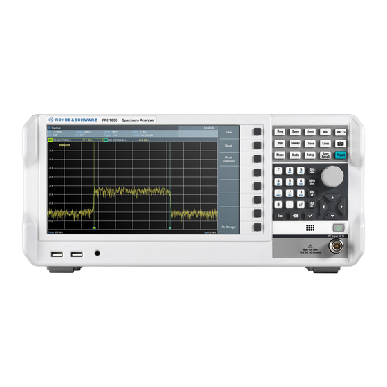
® Instrument Tour R&S Front Panel 4 Instrument Tour The R&S FPC has various connectors on the front and rear panel. 4.1 Front Panel Figure 4-1: Front panel of the R&S FPC USB ports (type A) Headphone jack Softkeys Signal source output Function keys and alphanumeric keypad RF input Power switch... - Page 19 ® Instrument Tour R&S Front Panel RF input The RF input with an impedance of 50 Ω allows you to connect a DUT to the R&S FPC. Typically, you connect the DUT with a cable and an appropriate connector (for example a male N connector). The frequency range of the RF input is specified in the datasheet.
-
Page 20: Rear Panel
® Instrument Tour R&S Rear Panel USB ports (type A) The two USB 2.0 ports on the front panel (type A) allow you to connect devices like memory sticks. Function keys and alphanumeric keypad The function keys provide access to the measurement settings and functions. The alphanumeric keypad allows you to enter alphanumeric data if necessary. - Page 21 ® Instrument Tour R&S Rear Panel Power supply The AC power supply and main power switch are located in a unit on the rear panel of the instrument. The main power switch has the following states. ● Position "1": The instrument is supplied with power. ●...
-
Page 22: Operation
® Operation R&S Manual Operation 5 Operation You can operate the R&S FPC manually with the keys available on its front panel, or remotely from another computer. ● Manual Operation....................19 ● Screen Layout......................22 ● Remote Operation....................25 5.1 Manual Operation The front panel of the R&S FPC provides various types of buttons (or keys) on its front panel that allow you operate it manually. - Page 23 ® Operation R&S Manual Operation that menu item, the R&S FPC opens an input field that allows you to change the center frequency. Depending on the parameter, pressing a softkey has one of the following effects. ● It opens an input field that allows you to modify a parameter by entering a specific value.
- Page 24 ® Operation R&S Manual Operation Figure 5-6: Input keys The input keys only have an effect when any kind of input field is active on the display. There are several types of input keys. ● Alphanumeric keys The alphanumeric keys allow you to enter numeric values or characters: the num- bers from 0 to 9, the alphabet, a minus and plus sign and a dot.
-
Page 25: Screen Layout
® Operation R&S Screen Layout If you confirm a value that has a unit with the "✓" key, the R&S FPC always uses the highest possible unit (for example GHz or s). In addition, the group of input keys also contains cursor keys and the rotary knob. Using the cursor keys The cursor keys do several things, depending on the situation when you use them. - Page 26 ® Operation R&S Screen Layout Figure 5-7: Screen layout in the spectrum application 1 = Title bar 2 = Input field 3 = Softkeys 4 = Measurement settings 5 = Trace information 6 = Marker information 7 = Limit line information 8 = Diagram area 9 = X-axis information 10 = Sweep count...
- Page 27 ® Operation R&S Screen Layout Softkeys can either perform a specific function or open an input field or dialog box. Measurement settings bar The measurement settings bar contains information about the current measurement settings. A blue dot in front of a setting indicates that automatic selection for that set- ting has been turned off.
-
Page 28: Remote Operation
® Operation R&S Remote Operation The diagram area can contain additional information. ● The sweep count indicates the process of trace averaging. The first number is the current measurement, the second number the total number of measurements inclu- ded in the trace averaging. ●... - Page 29 ® Operation R&S Remote Operation Alternatively, you can establish a connection via USB in the "USB" tab of the "Con- nection Manager". 5. Select "Instrument" > "Remote Display". The software shows a live simulation of the R&S FPC, including all keys available on the front panel.
- Page 30 ® Operation R&S Remote Operation Note: If you have a device that does not support ad-hoc connections, you have to connect both devices to an existing wireless infrastructure (for example through a router). When you connect both the mobile device and the R&S FPC to the infra- structure, you can use the app just like with an ad-hoc connection.
- Page 31 ® Operation R&S Remote Operation The user interface of the RsVisaTester opens. 4. Establish a connection to the R&S FPC. a) In the "Resource" field, enter the IP address of the R&S FPC you want to con- nect to. The form is tcpip::<ipaddress>[::protocol][::instrument], you can leave out the parts in brackets for now.
- Page 32 ® Operation R&S Remote Operation The R&S FPC resets the settings to their default value. "Write" button: whenever you want to send information to the instrument, use this button. 8. Enter another command, one that changes an instrument setting, for example sense:frequency:center 100mhz or the short form freq:cent 100MHZ.
- Page 33 ® Operation R&S Remote Operation Note that unless stated otherwise, a query always returns a numeric value in the SI derived unit (Hz in case of a frequency, not in kHz, MHz or GHz) and with several decimal places (usually six). Commands like SENSe:FREQuency:CENTer work a setting and a query.
- Page 34 ® Operation R&S Remote Operation TRACe:DATA is a query, but you have to state a parameter in that case. The parameter defines which data is returned (in this case, the data of trace 1; you could also display a second trace whose data you could query with TRACe:DATA TRACE2).
-
Page 35: Firmware Update
® Firmware Update R&S 6 Firmware Update New firmware versions usually contain new features, improvements of existing func- tionality, bug fixes etc. When a new firmware version is available, it is recommended to replace the old firmware with the new one. Updating the firmware The latest firmware version is available for download on the internet: www.rohde-schwarz.com/firmware/fpc... - Page 36 ® Firmware Update R&S The booting process continues. After a couple of seconds, the R&S FPC asks you if you really want to update the firmware. 9. Press the "Enter" ("✓") key to update the firmware. (You can cancel the firmware update with the "Esc" key.) The firmware update takes several minutes.
-
Page 37: Firmware Options
® Firmware Options R&S 7 Firmware Options You can equip the R&S FPC with optional functionality or firmware options like the ana- log demodulation application or the receiver application. These firmware options expand the functionality of the R&S FPC with new measurement functions settings etc. Installing firmware options To install a new firmware option, you have to enter a license key for validation. - Page 38 ® Firmware Options R&S This page contains three areas. ● The first area shows the details of the connected device, including the device ID and the IP address. ● The second area provides functionality to install and activate licenses. – "Install Registered License Keys And Activate License"...
- Page 39 ® Firmware Options R&S Follow this link if you have purchased an unregistered license and want to reg- ister it. – "Unregister License" Follow this link if you have installed a portable license. Portable licenses can be used with several device IDs. However, you have to unregister it on one device before you can use it on another.
-
Page 40: Preset
® Preset R&S 8 Preset Access: "Preset" Access (preset configuration): "Setup" > "User Preference" Access (factory reset): "Setup" > "Instrument Setup" Remote commands required to preset the system: ● Chapter 19.3, "Preset", on page 206 Before you prepare a measurement, it is recommended to preset the R&S FPC. During a preset, the R&S FPC resets all settings to their default state. - Page 41 ® Preset R&S 2. Select the "Instrument Setup" menu item to open the setup menu. 3. Select the "Reset To Factory Settings" menu item. The R&S FPC initiates the reset process and will ask you to confirm the reset. When you select "Yes", the system will be reset. User Manual 1178.4130.02 ─...
-
Page 42: Instrument Setup
® Instrument Setup R&S Network Configuration 9 Instrument Setup Access: "Setup" > "Instrument Setup" The "Instrument Setup" dialog box contains general properties of the R&S FPC that are independent of the measurement application you are using. ● BNC Connector Usage....................39 ●... - Page 43 ® Instrument Setup R&S Network Configuration When you are connecting the R&S FPC to a wired network (LAN), connect the R&S FPC with a standard LAN cable to a LAN port. The LAN port of the R&S FPC is on its rear panel. In case of a wired connection, you have to define several network properties to estab- lish a network connection.
-
Page 44: Date And Time
® Instrument Setup R&S Date and Time Connecting the R&S FPC to a WLAN Instead of connecting to a LAN, you can also connect the R&S FPC to a Wi-Fi network. You can use the Wi-Fi functionality to connect the R&S FPC to a hotspot (for example a router or mobile device configured as a hotspot) and operate it remotely. -
Page 45: Regional Settings
® Instrument Setup R&S Regional Settings 2. Select the "Instrument Setup" menu item to open the instrument setup dialog box. 3. Select the "Set Time" menu item in the "Date and Time" category. 4. Enter the time you want with the numeric keys. If you enter an invalid time, the R&S FPC highlights the invalid part and does not accept the input until you enter a valid time. -
Page 46: Display Settings
® Instrument Setup R&S Audio Settings 3. Select the "Date Format" menu item in the "Regional" category. 4. Select the date format of your choice. ● "dd/mm/yyyy": day/month/year ● "mm/dd/yyyy": month/day/year Selecting the length unit 1. Press the "Setup" key to open the setup menu. 2. -
Page 47: Power Settings
® Instrument Setup R&S Power Settings Defining the key click volume The key click volume defines the volume of the sound that the R&S FPC produces when you press a key or softkey. 1. Press the "Setup" key to open the setup menu. 2. - Page 48 ® Instrument Setup R&S Power Settings ● "On": The R&S FPC automatically boots when you use the main power switch on the rear panel. ● "Off": After using the main power switch, the R&S FPC is in stand-by mode. You have to turn it on with the power button on the front panel. User Manual 1178.4130.02 ─...
-
Page 49: Data Management
® Data Management R&S 10 Data Management Access (save and recall datasets): "Save Recall" Access (file manager): "Save Recall" > "File Manager" Access (user preferences): "Setup" > "User Preferences" Remote commands required for data management: ● Chapter 19.8, "Data Management", on page 216 The R&S FPC provides several tools to manage data related to your measurement tasks. - Page 50 ® Data Management R&S Storage devices You can store all this data on the internal memory of the R&S FPC or on external stor- age devices like memory sticks that you can connect to one of the USB ports of the R&S FPC.
- Page 51 ® Data Management R&S ● "Load" "Restoring datasets" on page 50. ● "Sort" Sorts the folder contents by certain criteria: alphabetically ("Sort on Name"), chronologically ("Sort by Date / Time") or by file size ("Sort on Size)". ● "Show Compatible" Filters the folder contents by their compatibility to the current measurement configuration.
- Page 52 ® Data Management R&S 3. If you want to save the dataset in a different folder or an external memory device, navigate to the folder you like. 4. Enter the file name in the "Save As" input field. The default file name for datasets is Dataset###.set with a new number in ascending order for each new dataset.
- Page 53 ® Data Management R&S 4. Select your preferred directory to store data in. 5. Confirm your selection with "Load". 6. Select the "Using Working Directory" menu item and turn it "On". Screenshots are automatically stored in the working directory you have selected. When you save a dataset, the R&S FPC automatically opens the file manager at the working directory.
- Page 54 ® Data Management R&S You can preview all available datasets in the selected folder with the "Prev" and "Next" menu items. When you have found a dataset that you would like to restore, you can restore it directly with the "Recall" menu item. Taking screenshots You can take and store a screenshot of the current screen anytime with the camera key.
-
Page 55: Signal Source Configuration
® Signal Source Configuration R&S 11 Signal Source Configuration Access: "Meas" > "Source" Remote commands to configure the signal source: ● Chapter 19.9, "Signal Source Configuartion", on page 226 Available for the R&S FPC1500 and in the spectrum and VNA applications. The signal source settings control the signal output on the corresponding RF connector on the front panel of the R&S FPC. - Page 56 ® Signal Source Configuration R&S by the offset, for example if the full span of your R&S FPC is 1 GHz, and you want an offset of 200 MHz, you have to reduce the span to 800 MHz. Defining the output level Risk of damage to the instrument or DUT Make sure that the DUT can handle the signal power that you output via the signal source.
-
Page 57: Calibration
® Calibration R&S 12 Calibration Access: "Meas" > "Source" > "Normalization" Remote commands to calibrate measurements: ● not supported Available for the R&S FPC1500 and in the spectrum and VNA applications. Before you measure S-parameters, you should calibrate the measurement. Calibration or system error correction is a separate measurement that determines systematic, reproducible errors. - Page 58 ® Calibration R&S The correction data between the reference points of the calibration is interpolated. Interpolation is used when you change one of the frequency parameters (start, stop or center frequency). In that case, the distribution of the measurement points is dif- ferent to the distribution during calibration.
- Page 59 ® Calibration R&S 2. Select the "Calibrate" menu item to enter the calibration menu. 3. Select the "Calibration Kits <x>" menu item. The R&S FPC opens a dialog box that contains a list of all calibration kit specifica- tions stored on the R&S FPC. 4.
- Page 60 ® Calibration R&S 3. Select the "Signal Source" menu item to open the signal source menu. 4. Turn on the "Tracking Generator". 5. Select the "Normalize S21" menu item. The R&S FPC asks you to set up a "Through" connection from port 1 to port 2. 6.
- Page 61 ® Calibration R&S The R&S FPC applies the correction values (menu item turns light blue). If you have a default calibration, default calibration is applied if you do not activate user calibration. User Manual 1178.4130.02 ─ 07...
-
Page 62: Measurement Wizard
® Measurement Wizard R&S 13 Measurement Wizard The measurement wizard is a tool that allows you to combine several individual mea- surement configurations to a sequence of measurements (or measurement set). Each individual measurement configuration is based on a dataset that you have previously saved. - Page 63 ® Measurement Wizard R&S Figure 13-1: Global measurement set settings 4. Define a "Measurement Set Name" and, if you like, a measurement "Description". 5. Optional: Select a different "Measurement Font". The measurement font selects the type of font used to display the instructions on the R&S FPC.
- Page 64 ® Measurement Wizard R&S Figure 13-2: Measurement settings for a dataset Do that for all datasets you have added to the measurement set. 10. Define the "Measurement Name" and instructions for that measurement. You can add instructions as text and as an image. 11.
- Page 65 ® Measurement Wizard R&S The R&S FPC shows the measurement specification. The measurement specifica- tion contains a list of the individual measurements (datasets) defined for the mea- surement set, and their current state ("<done>" or "<not done>"). Figure 13-3: Measurement specification shows the measurement sequence You can access the measurement specification with the "Measurement Specifica- tion"...
- Page 66 ® Measurement Wizard R&S 6. Start the measurement sequence with the "Start Measurement" menu item. The R&S FPC starts to go through the measurements that are part of the measure- ment set. The sequence of the measurement is as defined with the R&S Instru- mentView software.
- Page 67 ® Measurement Wizard R&S Ending a measurement sequence is possible when you turn on "Allow to skip measurements and finish wizard sequence" in the "Wizard Set" editor of the R&S InstrumentView software. ● "Cancel" Aborts the measurement sequence. The results of finished measurements are lost.
- Page 68 ® Measurement Wizard R&S Now that the results are available, you can start to compile a measurement report with the R&S InstrumentView software. 5. Start the "Report Generator". With the report editor, you can create measurement reports for the full measure- ment set or a selection of dataset only.
-
Page 69: The Spectrum Application
® The Spectrum Application R&S Configuration Overview 14 The Spectrum Application The spectrum analyzer application is the base application of the R&S FPC. It provides conventional spectrum analyzer functionality. In addition to basic frequency and time domain measurements, it also features several more sophisticated measurements like the channel power measurement or the OBW measurement (occupied bandwidth). - Page 70 ® The Spectrum Application R&S Configuration Overview Figure 14-1: Configuration overview in the spectrum application Accessing the configuration overview 1. Press the "Setup" key to open the setup menu. 2. Select the "Config Overview" menu item to open the configuration overview dialog box.
-
Page 71: Measurements And Result Displays
® The Spectrum Application R&S Measurements and Result Displays ● "Analysis" For more information about the contents of the "Analysis" pane, see Chapter 14.8, "Trace Configuration", on page 113. ● "Trigger" For more information about the contents of the "Trigger" pane, see Chapter 14.7, "Trigger Configuration",... - Page 72 ® The Spectrum Application R&S Measurements and Result Displays Frequency domain measurements In the frequency domain, the R&S FPC analyzes the input signal characteristics over a certain frequency span. You can use it, for example, to obtain basic measurement results like peak levels and the shape of the spectrum. The horizontal axis shows the frequency, the vertical axis shows the signal levels.
- Page 73 ® The Spectrum Application R&S Measurements and Result Displays ● Measuring the AM Modulation Depth..............79 ● Measuring the Occupied Bandwidth............... 81 ● Working with the Spectrogram Result Display............84 14.2.1 Measuring the Channel Power of Continuously Modulated Signals Access (measurement menu): "Meas" > "Measurement Mode" > "Channel Power" Remote commands to control channel power measurements: ●...
- Page 74 ® The Spectrum Application R&S Measurements and Result Displays 14.2.1.1 About the Measurement The following prerequisites and settings are necessary to obtain correct results for the channel power measurement. ● Define the correct channel bandwidth. Only the signal to be measured should be visible in the diagram. An additional sig- nal would falsify the measurement.
- Page 75 ® The Spectrum Application R&S Measurements and Result Displays The displayed result shows the highest channel power that has been measured (indicated by the "Max Power" result in the diagram header. 4. You can return to the normal power display by selecting the "Clear / Write" menu item instead.
- Page 76 ® The Spectrum Application R&S Measurements and Result Displays The R&S FPC opens a dialog box to select the standard. 3. Select one of the available standards. The R&S FPC loads the configuration of the selected standard. It automatically sets the span, resolution bandwidth, video bandwidth, sweep time and detector required by the standard.
- Page 77 ® The Spectrum Application R&S Measurements and Result Displays 14.2.2 Third Order Intermodulation Access: "Meas" > "Measurement Mode" > "Occupied Bandwidth" Remote commands to control the third order intermodulation measurement: ● Chapter 19.12.1.3, "Third Order Intermodulation", on page 238 Available with the optional "Advanced Measurements" application. Intermodulation is an effect that occurs when you transmit signals on two or more fre- quencies close to each other.
- Page 78 ® The Spectrum Application R&S Measurements and Result Displays The third order intermodulation (TOI) measurement analyzes the intermodulation prod- ucts that occur at the output of the DUT and calculates the third order intercept point. The IP3 is the theoretical intercept point of the DUTs desired output level and the level of the intermodulation products.
- Page 79 ® The Spectrum Application R&S Measurements and Result Displays The TDMA power measurement is a time domain measurement that determines the power of one of the time slots or the power of a burst. Selecting the TDMA power measurement 1. Press the "Meas" key to open the measurement menu. 2.
- Page 80 ® The Spectrum Application R&S Measurements and Result Displays Defining the reference level reference level is the power level that the R&S FPC expects at the RF input. When you select the reference level, make sure that you do not overload the R&S FPC by applying a signal whose power exceeds the maximum reference level.
- Page 81 ® The Spectrum Application R&S Measurements and Result Displays 2. Press the "Sweep" key to open the sweep menu. 3. Select the "Trigger" menu item to open the trigger menu. 4. Select the trigger source ("Video" or "External Rise / Fall" 5.
- Page 82 ® The Spectrum Application R&S Measurements and Result Displays Defining the number of harmonics The R&S FPC supports measurements on up to six harmonics. By default, the R&S FPC shows the signal's fundamental and its first harmonic. The fundamental and its harmonics are indicated by a marker that the R&S FPC places on the detected peaks.
- Page 83 ® The Spectrum Application R&S Measurements and Result Displays Selecting the AM modulation depth measurement 1. Press the "Meas" key to open the measurement menu. 2. Select the "Measurement Mode" menu item to select the measurement. 3. Select the "AM Modulation Depth" menu item. The R&S FPC measures the modulation depth by placing three markers on the trace.
- Page 84 ® The Spectrum Application R&S Measurements and Result Displays 14.2.6 Measuring the Occupied Bandwidth Access: "Meas" > "Measurement Mode" > "Occupied Bandwidth" Remote commands to control the occupied bandwidth measurement: ● Chapter 19.12.1, "Measurements and Result Displays", on page 232 Available with the optional "Advanced Measurements"...
- Page 85 ® The Spectrum Application R&S Measurements and Result Displays Only the signal to be measured should be visible in the diagram. An additional sig- nal would falsify the measurement. ● Define a sufficient resolution bandwidth. The resolution bandwidth should be between 1 % and 4 % of the channel band- width.
- Page 86 ® The Spectrum Application R&S Measurements and Result Displays The R&S FPC opens an input field to define the channel bandwidth. 3. Enter the channel bandwidth you need. Note: The minimum channel bandwidth that you can set is 2 kHz at a span of 1 kHz.
- Page 87 ® The Spectrum Application R&S Measurements and Result Displays It uses a resolution bandwidth of 1 MHz, a video bandwidth of 1 MHz and the peak detector. After finishing the automatic measurement, the R&S FPC sets the optimal reference level. Changing the span Usually, the span that the R&S FPC selects yields optimal results.
- Page 88 ® The Spectrum Application R&S Measurements and Result Displays move down one position, so that the present frame is always on top of the diagram. Therefore, the sequence of frames is chronological. Selecting the spectrogram result display 1. Press the "Meas" key to open the measurement menu. 2.
- Page 89 ® The Spectrum Application R&S Measurements and Result Displays The spectrogram result display is filled with new lines until you change a measure- ment setting. When you change a setting (for example the center frequency), the spectrogram clears and starts to fill again. 4.
- Page 90 ® The Spectrum Application R&S Measurements and Result Displays ● Two arrows (one up, one down) indicate that the spectrogram area displayed is somewhere in the middle of the available history. ● A single up arrow in the upper right corner of the spectrogram indicates that the lowest line of the spectrogram represents the end of the history buffer.
- Page 91 ® The Spectrum Application R&S Measurements and Result Displays Therefore you can adjust the color map to the overall shape of the signal you are mea- suring. Let us say, for example, that the signal has an amplitude range of about 30 dB with the maximum amplitude at about -80 dBm and the minimum amplitude at about -120 dBm.
- Page 92 ® The Spectrum Application R&S Measurements and Result Displays The changes however, still do not show signal differences in detail. The only thing that happened is that the colors have shifted, in the example to purple, because the color that corresponds to the reference level has shifted from red to purple. All other colors that are part of the color scheme are still unused, because the spectro- gram level range is still the same (100 dB).
- Page 93 ® The Spectrum Application R&S Measurements and Result Displays The best way to display a spectrogram is therefore to reduce the level range until the lowest signal part is mapped to the lower end of the color map and the highest signal part to the upper end of the color map.
- Page 94 ® The Spectrum Application R&S Measurements and Result Displays 4. Select the "Save" softkey to store the spectrogram. Now that you have saved the spectrogram, you can replay it any time you want. The number of spectrograms that you can store on the R&S FPC internal memory depends on the other datasets that are currently on the R&S FPC.
- Page 95 ® The Spectrum Application R&S Measurements and Result Displays 2. Select the "Time Line <x>" menu item. The R&S FPC opens an input field to define the position of the corresponding time line (T1 or T2). 3. Position the time line by entering a number or moving it with the rotary knob. Entering 0 sets the time line marker on the most recent frame.
-
Page 96: Frequency Configuration
® The Spectrum Application R&S Frequency Configuration Figure 14-6: Time lines and markers in the spectrogram Switching back to active spectrogram recording You can presume the spectrogram recording from playback mode. 1. Press the "Meas" key to open the measurement menu. 2. - Page 97 ® The Spectrum Application R&S Frequency Configuration ● In terms of a start and stop frequency from which the center frequency is automati- cally derived. ● In terms of a channel table that contains (frequency) information about a set of transmission channels.
- Page 98 ® The Spectrum Application R&S Frequency Configuration When you select the center frequency with the rotary knob or the cursor keys, the dis- tance of each step that you take depends on the span. With the rotary knob, the small- est possible step is a pixel.
- Page 99 ® The Spectrum Application R&S Frequency Configuration 14.3.2 Frequency Span The span is the frequency range that the measurement covers. You can measure the full frequency range of the R&S FPC, or a smaller part of it. The span also defines which frequency information is displayed in the measurement diagram - the span is the frequency range around the center frequency...
- Page 100 ® The Spectrum Application R&S Frequency Configuration Defining a start and stop frequency Defining a start a stop frequency is best suited for example for measurements on har- monics or signals whose exact frequency is unknown. When you define a start and stop frequency, the center frequency is automatically adjusted to be in the center of start and stop frequency.
-
Page 101: Amplitude Configuration
® The Spectrum Application R&S Amplitude Configuration After activating the channel table, the R&S FPC is configured according to the information contained in the channel table. Instead of a center frequency, the R&S FPC shows the currently active channel number including the name of the channel. - Page 102 ® The Spectrum Application R&S Amplitude Configuration If you need an input impedance of 75 Ω, you have to connect one of the supported matching pads to the RF input. When one of the supported matching pads is connec- ted, you can change the input impedance. The R&S FPC in that case automatically considers the conversion factor.
- Page 103 ® The Spectrum Application R&S Amplitude Configuration 3. Enter the reference level. When you change the reference level while a trace is already displayed, the R&S FPC adjusts the position of the trace. The current reference level is indicated in the status bar. A blue dot in front of the "Ref:"...
- Page 104 ® The Spectrum Application R&S Amplitude Configuration You can change the position of the reference level to another grid line, if required for any reason. 1. Press the "Ampt" key to open the amplitude menu. 2. Select the "Range / Ref Position" menu item to open the display range menu. 3.
- Page 105 ® The Spectrum Application R&S Amplitude Configuration 2. Select the "Attenuator" menu item to open the attenuator menu. 3. The R&S FPC provides several attenuation modes. ● "Manual Att <x> dB" Defines the attenuation manually in 5 dB steps. The range is from 0 dB to 40 dB.
- Page 106 ® The Spectrum Application R&S Amplitude Configuration Preamplifier OFF Preamplifier ON RF attenuation RF attenuation Reference level Low noise Low distortion Low noise Low distortion 21 dBm to 25 dBm 35 dB 40 dB 40 dB 40 dB 26 dBm to 30 dBm 40 dB 40 dB 40 dB...
- Page 107 ® The Spectrum Application R&S Amplitude Configuration Defining a display range The display range determines the scale or resolution of the y-axis. In the default state, the display range is a logarithmic scale over a 100 dB. This scale corresponds to a resolution of 10 dB per grid division. The R&S FPC provides other display ranges that either increase or decrease the resolution of the y-axis.
- Page 108 ® The Spectrum Application R&S Amplitude Configuration ers. Two transducers can be switched on at a time. The second transducer must be assigned the unit dB. The R&S FPC adds the two transducers to a total transducer. Units supported for transducer factors: ●...
-
Page 109: Bandwidth Configuration
® The Spectrum Application R&S Bandwidth Configuration If the unit of the transducer is dBμV/m or dBμA/m, this unit is also used for the R&S FPC level display. This means that both the level axis of the diagram and the level at the marker position are assigned the unit of the transducer. - Page 110 ® The Spectrum Application R&S Bandwidth Configuration 14.5.1 Resolution Filter The resolution filter (or IF filter) is a 3 dB bandpass filter located in the IF path of the analyzer. Its bandwidth determines how well individual spectral components can be separated from each other in frequency domain measurements.
- Page 111 ® The Spectrum Application R&S Bandwidth Configuration Automatically selects an appropriate resolution bandwidth depending on the current frequency span. Automatic adjustment of the sweep time In its default mode, the R&S FPC automatically adjusts the sweep time when you change the resolution bandwidth. This ensures that the settling time required for the selected resolution filter is properly taken into account.
-
Page 112: Sweep Configuration
® The Spectrum Application R&S Sweep Configuration frequency of the video filter will be rejected. The smaller the video bandwidth, the smaller the noise amplitude at the video filter output. The video bandwidth (VBW) has several effects on measurements. ● If you want to keep signals free of noise, you should select the smallest video bandwidth possible (≤... - Page 113 ® The Spectrum Application R&S Sweep Configuration 14.6.1 Sweep Time The sweep time (or measurement time) is the time that the analyzer requires to acquire and analyze the data in the selected frequency span. Large spans require more time to measure than small spans.
- Page 114 ® The Spectrum Application R&S Sweep Configuration In continuous mode, the R&S FPC repeats the measurement of the selected span over and over until you stop it deliberately. The measurement results are updated accord- ingly. In single sweep mode, the R&S FPC measures the frequency spectrum once and then stops without updating the results any longer.
-
Page 115: Trigger Configuration
® The Spectrum Application R&S Trigger Configuration ● For TDMA Power measurements. ● For measurements with a gated trigger. ● If the frequency span is smaller than the resolution bandwidth (RBW). ● If the the resolution bandwidth (RBW) is greater than 300 kHz. 14.7 Trigger Configuration Access: "Sweep"... -
Page 116: Trace Configuration
® The Spectrum Application R&S Trace Configuration "External Fall": the measurement starts when the trigger signal falls below 1.4 V (a TTL signal level). You can connect the external trigger source to the corresponding BNC connec- tor on the rear panel of the R&S FPC. Note that the BNC connector has to be configured as a trigger input in the... - Page 117 ® The Spectrum Application R&S Trace Configuration Selecting a trace The R&S FPC can display up to two traces at the same time, each with a different con- figuration. Before you configure a trace, you have to select the trace whose attributes you would like to change.
- Page 118 ® The Spectrum Application R&S Trace Configuration ● Trace Mode......................115 ● Detector.........................116 ● Memory Traces......................117 14.8.1 Trace Mode The trace mode determines the way the R&S FPC writes or displays the trace or which results are displayed. Note that each time you select another trace mode, the R&S FPC clears the trace memory.
- Page 119 ® The Spectrum Application R&S Trace Configuration Removes the trace from the diagram. Selecting the trace mode 1. Press the "Trace" key to open the trace menu. 2. Select the "Trace Mode" menu item to open the trace mode menu. 3.
- Page 120 ® The Spectrum Application R&S Trace Configuration The RMS detector measures the spectral power over one pixel. In case of power measurements, the RMS detector always shows the true power of a signal, regard- less of the shape of the signal. The RMS detector is best for measurements on digitally modulated signals because it provides stable and true power readings.
- Page 121 ® The Spectrum Application R&S Trace Configuration When you save a data set, the R&S FPC also stores the associated trace in the trace memory. If you restore it later, you can display the memory trace as if it is a normal trace.
-
Page 122: Marker Configuration
® The Spectrum Application R&S Marker Configuration Tip: To turn off trace mathematics, select the "Off"" menu item. If trace mathematics is active, the resulting trace can be adjusted in its position by selecting the "Math Position" menu item. Figure 14-17: Result of trace mathematics ("Trace - Memory") 14.9 Marker Configuration Access (marker menu): "Mkr"... - Page 123 ® The Spectrum Application R&S Marker Configuration Figure 14-18: Indicator of vertical marker position The marker coordinates are also shown in numerical form in the marker list above the diagram area. The marker list opens when you activate the first marker. Figure 14-19: Marker information in the diagram area and the marker list above the diagram The marker list contains the following information.
- Page 124 ® The Spectrum Application R&S Marker Configuration Positioning a marker 1. Press the "Mkr" key to open the marker menu. If, as yet, no marker is active, the R&S FPC automatically activates a normal marker ("M1") and positions it on the highest level that has been measured. In addition, the "Marker"...
- Page 125 ® The Spectrum Application R&S Marker Configuration Tip: You can turn on all six markers at the same time with the "All Markers On" menu item available in the marker menu. The R&S FPC positions the markers on the six highest signals in consecutive order. Selecting the marker type You can change the marker type for markers 2 to 6.
- Page 126 ® The Spectrum Application R&S Marker Configuration 2. Select the "Marker Display" menu item. 3. Select the input mode you prefer ("Frequency Display" or "Channel Display"). When you select the channel display, enter a channel number instead of a fre- quency to position the marker.
- Page 127 ® The Spectrum Application R&S Marker Configuration Keeping the marker on the peak When you turn on a marker, it remains on the initial frequency by default. Marker track- ing is a tool that allows you to keep track of a signal when its frequency changes. 1.
-
Page 128: Marker Functions
® The Spectrum Application R&S Marker Functions Figure 14-20: Marker search range lines 8. To use search range 1 for measurements, select the "Set to Search Range 1" menu item. The R&S FPC then uses the search range for the "Set To Peak", "Set To Next Peak", "Set To Minimum"... - Page 129 ® The Spectrum Application R&S Marker Functions ● Noise Measurement....................126 ● Frequency Counter....................126 ● Signal Bandwidth Measurement................127 ● Marker Demodulation....................128 14.10.1 Noise Measurement Access: "Mkr" > "Marker Mode" > "Noise" The marker noise measurement calculates the noise power density at the marker posi- tion in dBm/Hz.
- Page 130 ® The Spectrum Application R&S Marker Functions R&S FPC stops the measurement at the marker position for a short time and measures the frequency using the internal reference frequency. The accuracy of the results therefore depends only on the accuracy of the internal ref- erence frequency.
- Page 131 ® The Spectrum Application R&S Marker Functions Note: The distance to the reference marker is by default 3 dB below the reference marker. 14.10.4 Marker Demodulation Access: "Mkr" > "Marker Demodulation" The R&S FPC features an AM and FM demodulator to demodulate and monitor audio signals.
-
Page 132: Display Lines
® The Spectrum Application R&S Display Lines Defining the audio volume 1. Press the "Mkr" key to open the marker menu. 2. Select the "Marker Demodulation" menu item to open the marker demodulation menu. 3. Select the "Volume <x>" menu item. The R&S FPC opens an input field to define the demodulation volume. -
Page 133: Limit Lines
® The Spectrum Application R&S Limit Lines Figure 14-21: Display line at -38 dBm 14.12 Limit Lines Access (limit lines menu): "Lines" Limit lines are an analysis tool that allows you to compare the measured signal levels to signal specifications, and determine if the signal levels comply to the specifications. Remote commands to configure limit lines: ●... - Page 134 ® The Spectrum Application R&S Limit Lines You can create and edit limit lines with the R&S InstrumentView software package and then transfer them into the internal memory of the R&S FPC. The number of limit lines you can store in the memory depends on other datasets available on theR&S FPC or, if you are using an external storage device (for example memory stick), the size of it.
- Page 135 ® The Spectrum Application R&S Limit Lines 5. Enter the required threshold. The R&S FPC displays the threshold line. The threshold line is represented by a straight red line. Hiding a limit line Hiding a limit line allows you to switch quickly between showing and hiding a limit line and evaluate a limit check, without turning it off it completely.
- Page 136 ® The Spectrum Application R&S Limit Lines The audio signal is active when the "Audio Beep" menu item is highlighted. User Manual 1178.4130.02 ─ 07...
-
Page 137: The Receiver Application
® The Receiver Application R&S Measurements and Result Displays 15 The Receiver Application Available with the optional "Receiver" application. The receiver application measures the power level of a specific frequency or a custom- ized set of frequencies instead of sweeping over (parts of) the frequency spectrum. The R&S FPC shows the results in result displays that have been designed for just such measurement tasks. - Page 138 ® The Receiver Application R&S Measurements and Result Displays The bargraph measurement measures the signal level of a single frequency and shows the results in a bargraph. The bargraph result display is a basic result display that shows the signal level at a specific frequency.
-
Page 139: Frequency Scan
® The Receiver Application R&S Measurements and Result Displays 3. Press the "Trace" key to open the trace menu. 4. Select the "Trace <x>" menu item to select one of bargraphs. 5. Configure both bargraphs as you like. 15.1.2 Frequency Scan Access: "Meas"... - Page 140 ® The Receiver Application R&S Measurements and Result Displays The R&S FPC shows the scan diagram. For each measured frequency, it shows a vertical bar. Displaying a second trace You can display a second trace with a different configuration (trace mode or detector, for example).
-
Page 141: Frequency Configuration
® The Receiver Application R&S Frequency Configuration Distance to the limit line, if a limit line is active. If a second trace is active, the peak list shows the highest peaks of both traces. 15.1.3 Max Hold Information Access: "Meas" Both the bargraph measurement and the frequency scan contain max hold information. - Page 142 ® The Receiver Application R&S Frequency Configuration 15.2.1 Frequency Configuration (Bargraph) In bargraph measurement mode, the R&S FPC determines the power level of a single frequency only. You can measure any frequency supported by the R&S FPC. Defining the receiver frequency 1.
- Page 143 ® The Receiver Application R&S Frequency Configuration 15.2.2 Frequency Configuration (Frequency Scan) In frequency scan measurement mode, the R&S FPC determines the power levels of a set of single frequencies. The scan range defines the frequency range that the scan takes place in. Therefore, you have to define a start and stop frequency for the scan range and a scan step size.
- Page 144 ® The Receiver Application R&S Frequency Configuration Selecting the scale of the x-axis You can display the x-axis in a linear or a logarithmic scale. In a linear display, the frequencies are distributed linearly across the x-axis. That means the entire frequency range is divided by the number of measurement points, and the distance between measurement points is equal.
-
Page 145: Amplitude Configuration
® The Receiver Application R&S Amplitude Configuration 15.3 Amplitude Configuration Access: "Ampt" Access: "Setup" > "Config Overview" > "Amplitude" (selected settings) Access: "Setup" > "Config Overview" > "Input" (selected settings) Remote commands to configure the amplitude: ● Chapter 19.13.3, "Amplitude", on page 299 The following amplitude settings available in the receiver application are the same as in the spectrum application. -
Page 146: Bandwidth Configuration
® The Receiver Application R&S Bandwidth Configuration 4. Select the "Range / Ref Position" menu item to open the corresponding menu. 5. Select the "Ref Position <x>" menu item. 6. Move the position of the reference level on the bargraph scale to another position. The range is from 0 to 10. -
Page 147: Sweep Configuration
® The Receiver Application R&S Trace Configuration 15.5 Sweep Configuration Access: "Sweep" Access: "Setup" > "Config Overview" > "Bandwidth" (selected settings) Remote commands to control the measurement: ● Chapter 19.13.5, "Sweep Control", on page 300 The sweep menu provides settings to control the measurement and the way data is captured. -
Page 148: Limit Lines
® The Receiver Application R&S Marker Configuration Trace settings in the receiver application described elsewhere: ● "Select Trace": Chapter 14.8, "Trace Configuration", on page 113 ● "Trace Mode": Chapter 14.8.1, "Trace Mode", on page 115 (Note that the "Blank" and "View" trace modes are not available in the receiver.) ●... -
Page 149: Frequency Scans
® The Receiver Application R&S Marker Configuration Remote commands to control marker: ● Chapter 19.13.7, "Marker", on page 302 Note that markers are only available for frequency scans. Marker settings in the receiver application described elsewhere: ● "Mkr" > "Marker <x>": Chapter 14.9.1, "Marker Positioning", on page 120... -
Page 150: Analog Demodulation
® Analog Demodulation R&S Measurements and Result Displays 16 Analog Demodulation Available with the optional "AM, FM, ASK, FSK Demodulation" application. The analog demodulation application demodulates amplitude modulated (AM) and fre- quency modulated (FM) signals, and shows various aspects of the modulated and demodulated signal. - Page 151 ® Analog Demodulation R&S Measurements and Result Displays The demodulation starts directly after you have selected the measurement type. By default, the R&S FPC displays the results in a numerical result display, but you can also display the results in graphical result displays. Selecting the result display Both measurement types support a numerical and a graphical result display.
- Page 152 ® Analog Demodulation R&S Measurements and Result Displays Figure 16-2: Numerical results for an AM signal, including limit evaluation For each aspect, the R&S FPC shows the measured "Result", and, if you are using limits, the "Upper Limit" and "Lower Limit" value you have defined, including the "Sta- tus"...
-
Page 153: Frequency Configuration
® Analog Demodulation R&S Amplitude Configuration The SINAD measures the ratio of the total power to the power of noise and har- monic distortions. The noise and harmonic power is calculated inside the AF spec- trum span. The DC offset is removed before the calculation. ●... -
Page 154: Bandwidth Configuration
® Analog Demodulation R&S Bandwidth Configuration Adjusting the scale of the y-axis (AM signals) The y-axis shows the results as a percentage that represents the modulation depth. The modulation depth indicates how much the modulated signal deviates from the unmodulated signal (0 %). For AM signals, you can define the display range of the y-axis. - Page 155 ® Analog Demodulation R&S Bandwidth Configuration Selecting the demodulation bandwidth The demodulation bandwidth (DBW) determines the frequency range around the cen- ter frequency that is demodulated. It is not the 3 dB bandwidth of the filter but the use- ful bandwidth which is distortion-free regarding phase and amplitude. Basically, the demodulation bandwidth should be as narrow as possible to improve the S/N ratio.
- Page 156 ® Analog Demodulation R&S Bandwidth Configuration Selecting the FM broadcast time The FM broadcast time parameter selects the time constant of the deemphasis filter. This deemphasis filter is commonly used in FM broadcasting to improve the S/N ratio. In that case, a modulated signal is extorted by a pre-emphasis filter before transmis- sion, for example to eliminate frequencies that are more prone to interferences.
- Page 157 ® Analog Demodulation R&S Bandwidth Configuration Table 16-2: Measurement time calculation for audio lowpass filters Audio lowpass Measurement time DBW/1 DBW/10 x 10 DBW/30 x 30 DBW/100 x 100 Table 16-3: Minimum and maximum modulating frequencies for audio lowpass: DBW/1 Demodulation bandwidth Modulating frequency [Hz] Minimum...
-
Page 158: Sweep Configuration
® Analog Demodulation R&S Sweep Configuration Table 16-5: Minimum and maximum modulating frequencies for audio lowpass: DBW/30 Demodulation bandwidth Modulating frequency [Hz] Minimum Maximum 2000000 30303 989000 15152 650000 9848 500000 7576 300000 4545 200000 3030 100000 1515 50000 30000 20000 10000 Table 16-6: Minimum and maximum modulating frequencies for audio lowpass: DBW/100... -
Page 159: Limits
® Analog Demodulation R&S Limits The sweep menu provides settings to control the measurement and the way data is captured. Selecting the measurement mode The measurement mode defines how often the data is demodulated. In continuous mode, the R&S FPC demodulates the signal over and over until you stop it deliberately. - Page 160 ® Analog Demodulation R&S Limits 3. Navigate to the dataset that contains the limits you want to use. Make sure to select a dataset that is compatible to the current measurement: limits for AM measurements have file extension .amlim, those for FM measurements have the file extension .fmlim.
-
Page 161: Digital Demodulation
® Digital Demodulation R&S Measurements and Result Displays 17 Digital Demodulation Available with the optional "AM, FM, ASK, FSK Demodulation" application. The digital demodulation application demodulates signals modulated with amplitude- shift keying (ASK) and frequency-shift keying (FSK) modulation schemes. It analyzes these signals and shows various aspects of the modulated and demodulated signal. - Page 162 ® Digital Demodulation R&S Measurements and Result Displays Analyzer Device under Extraction of test (DUT) ideal signal Comparison Result display Figure 17-1: Demodulation principle The R&S FPC provides several measurements and numerical and graphical result dis- plays. These result displays show various aspects and characteristics of the demodula- ted signal.
- Page 163 ® Digital Demodulation R&S Measurements and Result Displays The demodulation starts directly after you have selected the measurement. By default, the R&S FPC displays the results in a graphical result display, but you can also display the results in graphical result displays. Selecting the result display Both measurement types support several result displays.
- Page 164 ® Digital Demodulation R&S Measurements and Result Displays Figure 17-3: Symbol stream of a 2ASK signal ● "Modulation Depth" (ASK): Shows the modulation depth of the signal (see "Modulation depth and modulation index" on page 162 for more information). Figure 17-4: Modulation depth of a 2ASK signal ●...
- Page 165 ® Digital Demodulation R&S Measurements and Result Displays ● "Modulation Error": Shows the modulation error over time (% for ASK and Hz for FSK). The modulation error shows the deviation of the measured symbols from the ideal symbol locations. The ideal symbol locations are defined in a ref- erence signal.
-
Page 166: Measurement Configuration
® Digital Demodulation R&S Measurement Configuration lation depth is the amount that the amplitude drops during the low state in %. The mod- ulation depth is therefore a value < 100 %. Another way to express the amplitude variations of an ASK modulated signal is the modulation index. - Page 167 ® Digital Demodulation R&S Measurement Configuration Analyzer (transmitter) Auto Auto Auto Set by user fct(CaptureOV, (function of (function of symbol rate) Tx filter) Tx filter) Lowpass Modulator Modulator ASK / FSK Demodulation & filter of I/Q with Tx + Rx with Tx filter filter demodulator...
- Page 168 ® Digital Demodulation R&S Measurement Configuration Defining the symbol rate The symbol rate defines the number of symbols that are transmitted per time unit (expressed in Hz in the R&S FPC). Therefore, the symbol rate also indicates how many transitions from one state to another (0 to 0, 0 to 1, etc.) are done in that time unit.
-
Page 169: Frequency Configuration
® Digital Demodulation R&S Frequency Configuration a = Minimum required signal level b = Time between bursts 1 = No burst, because signal level increase is not enough 2 = No burst, because burst is too short 3 = No burst, because signal level increase occurs too soon after the last event 4 = Burst, because signal level is high enough, burst is long enough and time between bursts was large enough When a burst was found, the R&S FPC tries to demodulate the signal based on the... -
Page 170: Amplitude Configuration
® Digital Demodulation R&S Amplitude Configuration If you do not know the frequency of the carrier signal, you have to find it out, for exam- ple by searching the frequency spectrum in the spectrum application in the area where you assume that the carrier is located. Frequency settings in the digital modulation application described elsewhere: ●... -
Page 171: Sweep Configuration
® Digital Demodulation R&S Sweep Configuration 2. Select the "Deviation Per Division" menu item. 3. Enter the deviation you like. The R&S FPC adjusts the scale of the y-axis accordingly. Note that the trace is also compressed or enlarged accordingly. 17.5 Sweep Configuration Access: "Sweep"... -
Page 172: Trigger Configuration
® Digital Demodulation R&S Trigger Configuration Single Measurement "Selecting the measurement mode" on page 168. Remote command: Measurement type: on page 262 INITiate:CONTinuous New measurement sequence: on page 263 INITiate[:IMMediate] 17.6 Trigger Configuration Access: "Sweep" > "Trigger" Remote commands to trigger measurements: ●... -
Page 173: Vector Network Analyzer
® Vector Network Analyzer R&S Measurements and Result Displays 18 Vector Network Analyzer Available for the R&S FPC1500 with the optional VNA application. The vector network analyzer (VNA) application provides the functionality to character- ize networks with one or two ports. The VNA application allows you to determine the reflection or transmission characteristics of the device under test (DUT). -
Page 174: Transmission Measurement (S21)
® Vector Network Analyzer R&S Measurements and Result Displays 18.1.1 Transmission Measurement (S21) Access: "Meas" > "Transmission S21" The transmission (S21) measurement measures how much of the stimulus signal passes through the DUT in forward direction (from port 1 to port 2). It is therefore an indicator of how much loss, or gain, is caused by the DUT. -
Page 175: 1-Port Cable Loss Measurement
® Vector Network Analyzer R&S Measurements and Result Displays R&S FPC Port 1 (RF Out) Figure 18-2: Setup of a reflection S11 measurement If you measure the reflection on a system with two or more system components, the results are an aggregate over these components. Therefore you can only see the aggregated magnitude of the reflected power in the selected frequency range. -
Page 176: Distance To Fault Measurement
® Vector Network Analyzer R&S Measurements and Result Displays If the cable loss is constant over a large span (for example for low center frequencies), you can select any span. Note that if the cable loss is greater than 20 dB, you are better off using the S21 mea- surement, because the cable loss measurement might yield invalid results. - Page 177 ® Vector Network Analyzer R&S Measurements and Result Displays Because of its sensitivity by first measuring in the frequency domain and subsequent IFFT, the measurement is able to locate faults in a cable accurately. To keep this accu- racy, the R&S FPC also accounts for any attenuation that occurs over distance in a cable.
-
Page 178: Measurement Formats
® Vector Network Analyzer R&S Measurements and Result Displays 18.1.5 Measurement Formats Access: "Meas" > "Format" You can select one of several formats in which you can display the results of the VNA measurements. Selecting the measurement format 1. Press the "Meas" key to open the measurement menu. 2. - Page 179 ® Vector Network Analyzer R&S Measurements and Result Displays Shows the magnitude of the reflected power (cable loss). This format is a refined method to calculate the cable loss. When you select the format, the R&S FPC asks you to calibrate the measurement with a short and an open.
-
Page 180: Dtf Configuration
® Vector Network Analyzer R&S Measurements and Result Displays When you evaluate the electrical length, you can define an additional offset for the electrical length to be considered in the measurement. 4. Select the "Length Offset" menu item. 5. Define an offset as necessary. 18.1.6 DTF Configuration Access: "Meas"... - Page 181 ® Vector Network Analyzer R&S Measurements and Result Displays 6. Select the "Clear Cable Model" menu item at any time if you want to perform mea- surements without using a specific cable model. Creating a custom cable model The R&S FPC provides two ways to define customized cable models. The first way is to define a cable model with the "Cable Model Editor"...
-
Page 182: Frequency Configuration
® Vector Network Analyzer R&S Frequency Configuration Defining the cable length The cable length is the sum of the start and stop distances you define for the measure- ment. If you do not know the exact length of the cable, define a length that is about 20 % to 50 % larger than the best estimate. - Page 183 ® Vector Network Analyzer R&S Frequency Configuration 2. Select the "Auto Span" menu item. The R&S FPC automatically calculates the best span for the best length resolution. If the required span is too large for the current center frequency, the R&S FPC changes the center frequency to the smallest possible frequency.
-
Page 184: Amplitude Configuration
® Vector Network Analyzer R&S Amplitude Configuration The R&S FPC couples the frequency and span settings across all measurements. 18.3 Amplitude Configuration Access: "Ampt" Access: "Setup" > "Config Overview" > "Amplitude" (selected settings) Remote commands to configure the amplitude: ● Chapter 19.16.2, "Amplitude", on page 328... -
Page 185: Bandwidth Configuration
® Vector Network Analyzer R&S Bandwidth Configuration Defining the display range The display range defines the scale of the vertical axis and therefore the amplitude between two horizontal grid lines. The unit depends on the measurement format. When you change the display range, you can increase or decrease the amplitude the R&S FPC displays and, for example, include signal parts that are outside the displayed screen area. -
Page 186: Sweep Configuration
® Vector Network Analyzer R&S Sweep Configuration Figure 18-5: Indicator of manual resolution bandwidth ● "RBW: Auto" Automatically selects an appropriate measurement bandwidth depending on the current frequency span. The automatically selected bandwidth is a compro- mise between measurement speed and performance. 18.5 Sweep Configuration Access: "Sweep"... -
Page 187: Trace Configuration
® Vector Network Analyzer R&S Marker Configuration Defining the number of measurement points The number of (measurement) points defines the number of measurements performed during a sweep. Thus, it indirectly sets the frequencies of those measurements. The distance from one measurement point to the next depends on the currently set fre- quency range (span divided by number of points). - Page 188 ® Vector Network Analyzer R&S Marker Configuration ● "Mkr→" > "Set to <x>": Chapter 14.9.2, "Automatic Marker Positioning", on page 123 ● "Mkr→" > "Marker Tracking": Chapter 14.9.2, "Automatic Marker Positioning", on page 123 ● "Mkr→" > "Search Ranges": Chapter 14.9.3, "Marker Search Ranges", on page 124 Using markers in the Smith diagram...
-
Page 189: Limit Line Configuration
® Vector Network Analyzer R&S Limit Line Configuration 3. Select the "Reference Impedance" menu item to define the reference impedance of your choice. The value range is from 1 mΩ to 10 kΩ. 18.8 Limit Line Configuration Access: "Lines" Remote commands to work with limit lines: ●... -
Page 190: Remote Control
® Remote Control R&S Remote Control Basics 19 Remote Control ● Remote Control Basics..................187 ● Common Commands.................... 202 ● Preset........................206 ● Network Connection....................207 ● System Configuration....................209 ● Display Settings....................215 ● Audio Settings.......................215 ● Data Management....................216 ● Signal Source Configuartion................. - Page 191 ® Remote Control R&S Remote Control Basics specific commands, error handling and the status registers. The tutorial "Automatic Measurement Control - A tutorial on SCPI and IEEE 488.2" from John M. Pieper (R&S order number 0002.3536.00) provides detailed information on concepts and definitions of SCPI.
- Page 192 ® Remote Control R&S Remote Control Basics 19.1.1.3 Protocols VXI-11 basics The VXI-11 standard is based on the ONC-RPC protocol which in turn relies on TCP/IP as the network/transport layer. The TCP/IP network protocol and the associated net- work services are preconfigured. TCP/IP ensures connection-oriented communication, where the order of the exchanged messages is adhered to and interrupted links are identified.
-
Page 193: Remote Control Connection
® Remote Control R&S Remote Control Basics Core channel (program, response, control messages) Instrument Controller Abort channel (abort) Interrupt channel (service request) Figure 19-2: VXI-11 channels between instrument and controller The number of controllers that can address an instrument is practically unlimited in the network. -
Page 194: Instrument Model And Command Processing
® Remote Control R&S Remote Control Basics cmd = "FREQ:CENT 100MHz" status = viWrite(vi, Cmd, Len(Cmd), retCount) //set span to 10 MHz cmd = "FREQ:SPAN 10MHz" status = viWrite(vi, Cmd, Len(Cmd), retCount) //set reference level to -10 dBm cmd = "DISP:TRAC:Y:RLEV -10dBm" status = viWrite(vi, Cmd, Len(Cmd), retCount) viclose vi viclose default RM... -
Page 195: Scpi Command Structure
® Remote Control R&S Remote Control Basics command recognition and execution. The receipt of DCL clears the input buffer and immediately resets the command recognition. 19.1.3.2 Command Recognition Here the expression "instrument hardware" denotes the part of the instrument fulfilling the actual instrument function - signal generation, measurement etc. - Page 196 ® Remote Control R&S Remote Control Basics 19.1.4.1 Syntax for Common Commands Common (= device-independent) commands consist of a header preceded by an aster- isk (*), and possibly one or more parameters. Table 19-1: Examples of common commands *RST RESET Resets the instrument.
- Page 197 ® Remote Control R&S Remote Control Basics Case-insensitivity Upper case and lower case notation only serves to distinguish the two forms in the manual, the instrument itself is case-insensitive. Numeric Suffixes If a command can be applied to multiple instances of an object, e.g. specific channels or sources, the required instances can be specified by a suffix added to the command.
- Page 198 ® Remote Control R&S Remote Control Basics Optional mnemonics with numeric suffixes Do not omit an optional mnemonic if it includes a numeric suffix that is relevant for the effect of the command. Example: Definition:DISPlay[:WINDow<1...4>]:MAXimize <Boolean> Command: DISP:MAX ON refers to window 1. In order to refer to a window other than 1, you must include the optional WINDow parameter with the suffix for the required window.
- Page 199 ® Remote Control R&S Remote Control Basics ● N (nano) Example: SENSe:FREQ:STOP 1.5GHz = SENSe:FREQ:STOP 1.5E9 Some settings allow relative values to be stated in percent. According to SCPI, this unit is represented by the PCT string. Example: HCOP:PAGE:SCAL 90PCT Special Numeric Values The following mnemonics are special numeric values.
- Page 200 ® Remote Control R&S Remote Control Basics Example: Setting command: HCOPy:DEV:COL ON Query: HCOPy:DEV:COL? Response: 1 Text Parameters Text parameters observe the syntactic rules for mnemonics, i.e. they can be entered using a short or long form. Like any parameter, they have to be separated from the header by a white space.
- Page 201 ® Remote Control R&S Remote Control Basics Table 19-2: Syntax elements The colon separates the mnemonics of a command. The semicolon separates two commands of a command line. It does not alter the path. The comma separates several parameters of a command. The question mark forms a query.
- Page 202 ® Remote Control R&S Remote Control Basics 19.1.4.5 Structure of a Command Line A command line may consist of one or several commands. It is terminated by one of the following: ● <New Line> ● <New Line> with EOI ● EOI together with the last data byte Several commands in a command line must be separated by a semicolon ";".
-
Page 203: Command Sequence And Synchronization
® Remote Control R&S Remote Control Basics ● Truth values (Boolean values) are returned as 0 (for OFF) and 1 (for ON). Example: Setting command: HCOPy:DEV:COL ON Query: HCOPy:DEV:COL? Response: 1 ● Text (character data) is returned in a short form. Example: Setting command: HCOPy:PAGE:ORIentation LANDscape Query: HCOP:PAGE:ORI? - Page 204 ® Remote Control R&S Remote Control Basics As a general rule, send commands and queries in different program messages. Example: Overlapping command with *OPC The instrument implements INITiate[:IMMediate] as an overlapped command. Assuming that INITiate[:IMMediate] takes longer to execute than *OPC, sending the following command sequence results in initiating a sweep and, after some time, setting the OPC bit in the ESR: INIT;...
-
Page 205: Common Commands
® Remote Control R&S Common Commands *OPC with a service request 1. Set the OPC mask bit (bit no. 0) in the ESE: *ESE 1 2. Set bit no. 5 in the SRE: *SRE 32 to enable ESB service request. 3. - Page 206 ® Remote Control R&S Common Commands ..........................204 *OPC ...........................204 *OPT? ..........................204 *RST ..........................204 *SRE ...........................205 *STB? ..........................205 *TRG ........................... 205 *TST? ..........................205 *WAI *CLS Clear status Sets the status byte (STB), the standard event register (ESR) and the EVENt part of the QUEStionable and the OPERation registers to zero.
- Page 207 ® Remote Control R&S Common Commands *IST? Individual status query Returns the contents of the IST flag in decimal form. The IST flag is the status bit which is sent during a parallel poll. Return values: <ISTflag> 0 | 1 Usage: Query only *OPC...
- Page 208 ® Remote Control R&S Common Commands Parameters: <Contents> Contents of the service request enable register in decimal form. Bit 6 (MSS mask bit) is always 0. Range: 0 to 255 *STB? Status byte query Reads the contents of the status byte in decimal form. Usage: Query only *TRG...
-
Page 209: Preset
® Remote Control R&S Preset 19.3 Preset ......................206 SYSTem:PRESet ....................206 SYSTem:PRESet:FACTory ....................206 SYSTem:PRESet:MODE ....................207 SYSTem:PRESet:USER SYSTem:PRESet Resets the R&S FPC to its default state. The R&S FPC supports two different preset modes (default preset or user-defined pre- set). You can select the preset mode with SYSTem:PRESet:MODE. Example: //Reset the R&S FPC SYST:PRES... -
Page 210: Network Connection
® Remote Control R&S Network Connection SYSTem:PRESet:USER <Preset> This command selects a dataset whose configuration serves as a user-defined preset state. Prerequisites for this command ● Select user-defined preset mode (SYSTem:PRESet:MODE). Parameters: <Preset> String containing the path and name of the file, including the file- name extension (.set). - Page 211 ® Remote Control R&S Network Connection Example: //Select gateway SYST:COMM:SOCK:DHCP OFF SYST:COMM:LAN:GAT '0.0.0.0' Manual operation: "LAN" on page 356 SYSTem:COMMunicate:LAN:SUBMask <SubnetMask> This command defines the subnet mask of the R&S FPC. Prerequisites for this command ● Turn off DHCP (SYSTem:COMMunicate:SOCKet:DHCP[:STATe]). Parameters: <SubnetMask>...
-
Page 212: System Configuration
® Remote Control R&S System Configuration Manual operation: "LAN" on page 356 19.5 System Configuration ..............209 DIAGnostic[:SERVice]:IDENtification:MATerial? ..............209 DIAGnostic[:SERVice]:IDENtification:SERial? ....................210 DISPlay:DATE:FORMat ..................... 210 SYSTem:BNC:MODE ......................210 SYSTem:DATE .....................211 SYSTem:ERRor:ALL? ...................211 SYSTem:ERRor:CODE:ALL? ..................211 SYSTem:ERRor:CODE[:NEXT]? ....................212 SYSTem:ERRor:COUNt? ....................212 SYSTem:ERRor[:NEXT]? ....................212 SYSTem:HELP:HEADers? ....................212 SYSTem:HELP:SYNTax? - Page 213 ® Remote Control R&S System Configuration Usage: Query only DISPlay:DATE:FORMat <DateFormat> This command selects the date format. Parameters: <DateFormat> DDMMyyyy | MMDDyyyy *RST: DDMMyyyy Example: //Select date format DISP:DATE:FORM DDMMyyyy Manual operation: "Regional" on page 356 SYSTem:BNC:MODE <Usage> This command configures the BNC connector on the rear panel of the R&S FPC. Parameters: <Usage>...
-
Page 214: System:error:all
® Remote Control R&S System Configuration SYSTem:ERRor:ALL? This command queries the complete error queue. The number of values depends on the length of the queue. If the error queue is empty, the command returns 0, 'No error'. Return values: <ErrorNumber> Number that contains information about the error. -
Page 215: System:error:count
® Remote Control R&S System Configuration SYSTem:ERRor:COUNt? This command queries the number of errors currently in the error queue. Return values: <NumErrors> <numeric value> Example: //Query the number of errors in the error queue SYST:ERR:COUN? Usage: Query only SYSTem:ERRor[:NEXT]? This command queries the oldest entry in the error queue and deletes it. If the error queue is empty, the command returns 0, 'No error'. -
Page 216: System:language:catalog
® Remote Control R&S System Configuration SYSTem:LANGuage <Language> This command selects the language of the user interface. You can query a list of available languages with SYSTem:LANGuage:CATalog? Parameters: <Language> String containing the language. Example: //Select the language SYST:LANG 'english' Manual operation: "Regional"... - Page 217 ® Remote Control R&S System Configuration ● SYSTem:MEMory:USED: Queries how much memory is currently used. Return values: <MemorySize> <numeric value> Example: //Query free RAM SYST:MEM:FREE? Usage: Query only SYSTem:TIME <Hour>, <Minutes>, <Seconds> This command defines the time of the internal clock. Parameters: <Hour>...
-
Page 218: Display Settings
® Remote Control R&S Audio Settings Parameters: <Unit> FEET Length units in feet. METers Length units in meter. *RST: METers Example: //Select length unit UNIT:LENG MET 19.6 Display Settings ...................... 215 DISPlay:BRIGhtness ...................215 SYSTem:DISPlay:UPDate[:STATe] DISPlay:BRIGhtness <Brightness> This command defines the brightness of the display backlight. Parameters: <Brightness>... -
Page 219: Data Management
® Remote Control R&S Data Management SYSTem:BEEPer:KEY:VOLume <Volume> This command defines the volume of the keyboard click sound. Parameters: <Volume> <numeric value> Range: 0 to 1 *RST: 0.3 (30%) Example: //Select the key click volume SYST:BEEP:KEY:VOL 0.10 Manual operation: "Audio" on page 356 SYSTem:BEEPer:POVerload[:STATe] <State>... - Page 220 ® Remote Control R&S Data Management .......................218 MMEMory:CATalog? ..................218 MMEMory:CATalog:DIRectories? ....................219 MMEMory:CDIRectory ......................219 MMEMory:COPY ......................219 MMEMory:DATA ......................220 MMEMory:DELete ......................221 MMEMory:FILE ....................221 MMEMory:FILE:DATE ..................... 222 MMEMory:FILE:TIME ....................222 MMEMory:LOAD:STATe ....................223 MMEMory:MDIRectory ......................223 MMEMory:MOVE ......................224 MMEMory:NAME ....................224 MMEMory:RDIRectory ....................224...
-
Page 221: Mmemory:catalog
® Remote Control R&S Data Management HCOPy[:IMMediate] This command takes a screenshot of the current display contents and stores it on the R&S FPC internal memory. Prerequisites for this command ● Define a file name for the screenshot (MMEMory:NAME). Example: //Make and store a screenshot of the current screen in a file 'Test.png'. -
Page 222: Mmemory:cdirectory
® Remote Control R&S Data Management Usage: Query only Manual operation: "File Manager" on page 359 MMEMory:CDIRectory <PathName> This command changes the current directory. Parameters: <PathName> String containing the path to the destination directory. The path and file name comply with Windows conventions. Note that the folder references in the string are case-sensitive. -
Page 223: Mmemory:delete
® Remote Control R&S Data Management Prerequisites for this command ● Create an empty file (MMEMory:NAME). Parameters: <FileName> String containing the path and name of the file, including the file- name extension. The path and file name comply with Windows conventions. Note that the folder and filename references in the string are case- sensitive. -
Page 224: Mmemory:file
® Remote Control R&S Data Management Example: //Delete a file MMEM:DEL '\Public\funny\result.set' Usage: Setting only Manual operation: "File Manager" on page 359 MMEMory:FILE <FileName>[, <BlockData>] This command creates a file. If you do not define the block data, the command creates an empty file. You can add block data later with MMEMory:DATA. -
Page 225: Mmemory:file:time
® Remote Control R&S Data Management <Month> <numeric value> (integer) Range: 1 to 12 <Day> <numeric value> (integer) Range: 1 to 31 Example: //Change date stamp of result.set file MMEM:FILE:TIME 1,'\Public\result.set', 2006,04,01 MMEMory:FILE:TIME <FileName>[, <Hour>, <Minutes>, <Seconds>] This command defines the time stamp of a file. Parameters: <FileName>... -
Page 226: Mmemory:mdirectory
® Remote Control R&S Data Management Manual operation: "Recall" on page 358 "Recall Screenshot" on page 358 "File Manager" on page 359 MMEMory:MDIRectory <Directory> This command creates a directory. Setting parameters: <Directory> String containing the path and new directory name. The path and file name comply with Windows conventions. -
Page 227: Mmemory:name
® Remote Control R&S Data Management MMEMory:NAME <FileName> This command defines the path and file name of a screenshot. You can take the actual screenshot with HCOPy[:IMMediate]. Parameters: <FileName> String containing the path and name of the file, including the file- name extension (.png or .jpg). -
Page 228: System:set
® Remote Control R&S Data Management Manual operation: "Save" on page 358 "File Manager" on page 359 SYSTem:SET? This command queries the the contents of the currently active dataset and returns them in binary format. Return values: <Data> <block data> Contents of the dataset in binary format. -
Page 229: Signal Source Configuartion
® Remote Control R&S Signal Source Configuartion Parameters: <FileName> String containing the path and name of the dataset. The path and file name comply with Windows conventions. Note that the folder and filename references in the string are case- sensitive. Example: //Remove write-protection from a file SYST:SET:UNL '\Public\funny\result.set'... - Page 230 ® Remote Control R&S Signal Source Configuartion Prerequisites for this command ● Turn on signal source (SOURce:TG[:STATe]). ● Turn off tracking generator (SOURce:TG:AUTO). ● Select fixed frequency mode (SOURce:TG:FREQuency:AUTO). Parameters: <Frequency> <numeric value> Default unit: Hz Example: //Define fix frequency of generated signal SOUR:TG ON SOUR:TG:FREQ:AUTO OFF SOUR:TG:FREQ 100MHZ...
-
Page 231: Calibration
® Remote Control R&S Calibration Prerequisites for this command ● Turn on signal source (SOURce:TG[:STATe]). Parameters: <Level> <numeric level> *RST: Default unit: dBm Example: //Define signal source output power SOUR:TG ON SOUR:TG:POW -10DBM Manual operation: "Level" on page 367 SOURce:TG[:STATe] <State> This command turns the signal source on and off. - Page 232 ® Remote Control R&S Calibration Example: //Abort calibration CAL:STAR? S11C 'Connect Open to Port 1' CAL:ABOR Usage: Event Manual operation: "Calibrate" on page 397 CALibration<n>:CONTinue? This command resumes calibration after a calibration standard has been connected. Suffix: <n> irrelevant Return values: <Instructions>...
- Page 233 ® Remote Control R&S Calibration Example: //Query calibration type CAL:MODE? Usage: Query only Manual operation: "Calibrate" on page 397 CALibration<n>:STARt? <CalibrationMethod> This command selects a calibration method and initiates calibration. After the command has been sent, it returns instructions on what to do to continue the calibration process and finish it successfully.
-
Page 234: Applications
® Remote Control R&S Applications CALibration<n>:STATus? This command queries calibration status for the current measurement. Suffix: <n> irrelevant Return values: <Status> String containing the calibration status. NORMalized Default calibration or user calibration is active. APPRoximated Approximate calibration. Measurement uncertainty must be anticipated. -
Page 235: Remote Commands Of The Spectrum Application
® Remote Control R&S Remote Commands of the Spectrum Application Parameters: <Application> ADEMod Selects the analog demodulation application. DDEMod Selects the digital demodulation application. Select the vector network analyzer application. RECeiver Selects the receiver application. SPECtrum Selects the spectrum application. Example: //Select spectrum application INST SAN... - Page 236 ® Remote Control R&S Remote Commands of the Spectrum Application 19.12.1.1 Power Measurements The following commands are available for all power measurements (channel power, occupied bandwidth etc.) ............233 CALCulate<n>:MARKer<m>:FUNCtion:LEVel:ONCE ............ 233 CALCulate<n>:MARKer<m>:FUNCtion:POWer:PRESet ........234 CALCulate<n>:MARKer<m>:FUNCtion:POWer:PRESet:CHECk? ............ 234 CALCulate<n>:MARKer<m>:FUNCtion:POWer:RESult? ............. 235 CALCulate<n>:MARKer<m>:FUNCtion:POWer:SELect .............236 CALCulate<n>:MARKer<m>:FUNCtion:POWer[:STATe] CALCulate<n>:MARKer<m>:FUNCtion:LEVel:ONCE...
- Page 237 ® Remote Control R&S Remote Commands of the Spectrum Application Setting parameters: <Standard> String containing the file name of the standard. Make sure to use the correct file extension (for exam- ple .chpstd for channel power measurements or .obwstd for occupied bandwidth measurements.
- Page 238 ® Remote Control R&S Remote Commands of the Spectrum Application For the harmonic distortion and AM modulation depth measurements, use the following commands to query results: ● CALCulate<n>:MARKer<m>:FUNCtion:HARMonics:DISTortion? ● CALCulate<n>:MARKer<m>:FUNCtion:MDEPth:RESult? Suffix: <n>, <m> irrelevant Query parameters: <Measurement> Return values: <Power> The return values depend on the power measurement.
- Page 239 ® Remote Control R&S Remote Commands of the Spectrum Application Note: ● To turn on the harmonic disortion measurement, use CALCulate<n>: MARKer<m>:FUNCtion:HARMonics[:STATe]. ● To turn on the AM modulation depth measurement, use CALCulate<n>: MARKer<m>:FUNCtion:MDEPth[:STATe]. Suffix: <n>, <m> irrelevant Parameters: <Measurement> CPOWer Selects the channel power measurement.
- Page 240 ® Remote Control R&S Remote Commands of the Spectrum Application 19.12.1.2 Channel Power The following remote commands are exclusive to the channel power measurement..........237 CALCulate<n>:MARKer<m>:FUNCtion:CPOWer:BANDwidth ............237 CALCulate<n>:MARKer<m>:FUNCtion:CPOWer:MODE ............238 CALCulate<n>:MARKer<m>:FUNCtion:CPOWer:UNIT ..........238 CALCulate<n>:MARKer<m>:FUNCtion:POWer:RESult:PHZ CALCulate<n>:MARKer<m>:FUNCtion:CPOWer:BANDwidth <Bandwidth> This command defines the channel bandwidth for channel power measurements. Prerequisites for this command ●...
- Page 241 ® Remote Control R&S Remote Commands of the Spectrum Application CALCulate<n>:MARKer<m>:FUNCtion:CPOWer:UNIT <Unit> This command selects the unit of the for channel power measurements. Prerequisites for this command ● Select the channel power measurement (CALCulate<n>:MARKer<m>: FUNCtion:POWer:SELect). Suffix: <n> irrelevant <m> Marker Parameters: <Unit>...
- Page 242 ® Remote Control R&S Remote Commands of the Spectrum Application Prerequisites for this command ● Turn on TOI measurement (CALCulate<n>:MARKer<n>:FUNCtion:TOI[: STATe]). Suffix: <n>, <m> irrelevant Return values: <TOI> <numeric value> Default unit: dBm Example: //Query TOI result CALC:MARK:FUNC:TOI ON CALC:MARK:FUNC:TOI:SEAR CALC:MARK:FUNC:TOI:RES? Usage: Query only...
- Page 243 ® Remote Control R&S Remote Commands of the Spectrum Application Parameters: <State> ON | 1 Turns on the third order intermodulation measurement. OFF | 0 Performs a basic spectrum measurement. *RST: Example: //Measure the TOI CALC:MARK:FUNC:TOI ON Manual operation: "Third Order Intermod." on page 361 19.12.1.4 Occupied Bandwidth...
- Page 244 ® Remote Control R&S Remote Commands of the Spectrum Application Parameters: <Percentage> <numeric value> Range: 10 to 99.9% *RST: Example: //Define power percentage CALC:MARK:FUNC:OBW:BAND:PCT 95 Manual operation: "% Power Bandwidth" on page 367 19.12.1.5 TDMA Power The following remote commands are exclusive to the TDMA power measurement. Commands to configure TDMA power measurements described elsewhere.
- Page 245 ® Remote Control R&S Remote Commands of the Spectrum Application CALCulate<n>:MARKer<m>:FUNCtion:HARMonics:DISTortion? <ResultType> This command queries the total harmonic distortion of the signal. To get a valid result, you have to perform a complete sweep with synchronization to the sweep end between activating the delta marker and reading out the result. This is only possible in single sweep mode.
- Page 246 ® Remote Control R&S Remote Commands of the Spectrum Application Example: CALCulate<n>:MARKer<m>:FUNCtion:HARMonics: PRESet Usage: Query only Manual operation: "Harmonics" on page 365 CALCulate<n>:MARKer<m>:FUNCtion:HARMonics:NHARmonics <Harmonics> This command defines the number of harmonics that are analyzed. Prerequisites for this command ● Turn on the harmonic distortion measurement (CALCulate<n>:MARKer<m>: on page 244).
- Page 247 ® Remote Control R&S Remote Commands of the Spectrum Application CALCulate<n>:MARKer<m>:FUNCtion:HARMonics[:STATe] <State> This command turns the harmonic distortion measurement on and off. Suffix: <n>, <m> irrelevant Parameters: <State> ON | 1 Turns on the harmonic distortion measurement. OFF | 0 Performs a basic spectrum measurement.
- Page 248 ® Remote Control R&S Remote Commands of the Spectrum Application Prerequisites for this command ● Turn on modulation depth measurement (CALCulate<n>:MARKer<m>: FUNCtion:MDEPth[:STATe]). Suffix: <n>, <m> irrelevant Return values: <ModulationDepth> <numeric value> Modulation depth in %. Example: //Query the AM modulation depth. CALC:MARK:FUNC:MDEP:RES? Usage: Query only...
- Page 249 ® Remote Control R&S Remote Commands of the Spectrum Application ................... 251 [SENSe:]FREQuency:SPAN:FULL ................... 251 [SENSe:]FREQuency:STARt ....................251 [SENSe:]FREQuency:STOP [SENSe:]CHANnel <ChannelNumber> This command selects the channel to be analyzed. Prerequisites for this command ● Select channel table frequency mode ([SENSe:]FREQuency:INPut:MODE). Parameters: <ChannelNumber>...
- Page 250 ® Remote Control R&S Remote Commands of the Spectrum Application [SENSe:]CHANnel:TABLe:SELect <ChannelTable> This command selects a channel table configured for the link direction you have selected with [SENSe:]CHANnel:TABLe:SET. Note that if you have previously selected a channel table with [SENSe:]CHANnel: or [SENSe:]CHANnel:TABLe:SELect:UPLink, this TABLe:SELect:DOWNlink command replaces that file.
-
Page 251: Remote Command: [Sense:]Frequency:center
® Remote Control R&S Remote Commands of the Spectrum Application [SENSe:]FREQuency:CENTer <Frequency> This command defines the center frequency of the R&S FPC. In the spectrum application, the command also defines the frequency for time domain measurements (span = 0). Parameters: <Frequency>... - Page 252 ® Remote Control R&S Remote Commands of the Spectrum Application Parameters: <StepSizeCoupling> CENTer Step size equals the current center frequency. DIVTen Couple the step size to the span (10 %). Turn off the coupling (manual step size). You can define a manual step size with [SENSe:]FREQuency: CENTer:STEP.
- Page 253 ® Remote Control R&S Remote Commands of the Spectrum Application ● [SENSe:]FREQuency:STARt ● [SENSe:]FREQuency:STOP Parameters: <OperationMode> Select the time domain (span = 0) FIXed Select the time domain (span = 0) SWEep Select the frequency domain (span > 0). *RST: SWEep Example: //Activate frequency domain measurements...
- Page 254 ® Remote Control R&S Remote Commands of the Spectrum Application [SENSe:]FREQuency:SPAN:FULL This command restores the full span. Refer to the datasheet for details on the frequency range of your R&S FPC. Example: //Restore full span FREQ:SPAN:FULL Usage: Event Manual operation: "Full Span"...
- Page 255 ® Remote Control R&S Remote Commands of the Spectrum Application 19.12.3 Amplitude ..............252 DISPlay<n>[:WINDow]:TRACe<t>:Y:SPACing ..............252 DISPlay<n>[:WINDow]:TRACe<t>:Y[:SCALe] ............253 DISPlay<n>[:WINDow]:TRACe<t>:Y[:SCALe]:ADJust ............253 DISPlay<n>[:WINDow]:TRACe<t>:Y[:SCALe]:RLEVel ........... 254 DISPlay<n>[:WINDow]:TRACe<t>:Y[:SCALe]:RLEVel:OFFSet ........... 254 DISPlay<n>[:WINDow]:TRACe<t>:Y[:SCALe]:RPOSition ......................255 INPut:ATTenuation ....................255 INPut:ATTenuation:AUTO ....................256 INPut:ATTenuation:MODE ......................256 INPut:GAIN:STATe ......................256 INPut:IMPedance ....................257 INPut:IMPedance:PAD...
- Page 256 ® Remote Control R&S Remote Commands of the Spectrum Application Prerequisites for this command ● Select logarithmic scale for the y-axis (DISPlay<n>[:WINDow]:TRACe<t>:Y: SPACing). For a linear scale, you cannot modify the display range as it is fixed. Suffix: <n> irrelevant <t>...
- Page 257 ® Remote Control R&S Remote Commands of the Spectrum Application Parameters: <ReferenceLevel> <numeric value> The unit depends on UNIT<n>:POWer. The available value range is specified in the data sheet. *RST: -20 dBm Example: //Define reference level UNIT:POW DBM DISP:TRAC:Y:RLEV –60 Manual operation: "Reference Level"...
- Page 258 ® Remote Control R&S Remote Commands of the Spectrum Application Parameters: <Position> <numeric value> (integer) Range: 0 to 10 *RST: Example: //Set the reference position to the 5th grid line DISP:TRAC:Y:SPAC LOG DISP:TRAC:Y:RPOS 5 Manual operation: "Range / Ref Position" on page 370 "Range / Ref Position"...
- Page 259 ® Remote Control R&S Remote Commands of the Spectrum Application INPut:ATTenuation:MODE <AttenuationMode> This command selects the attenuation mode. Prerequisites for this command ● Select attenuation automatically (INPut:ATTenuation:AUTO). Parameters: <AttenuationMode> LDIStortion Select "Auto Low Distortion" mode. LNOise Select "Auto Low Noise" mode. *RST: LNOise Example:...
- Page 260 ® Remote Control R&S Remote Commands of the Spectrum Application Parameters: <Impedance> 50 | 75 *RST: Default unit: Ω Example: //Select input impedance INP:IMP:PAD RAZ INP:IMP 75 Manual operation: "Impedance" on page 370 "Impedance" on page 381 "Impedance" on page 389 INPut:IMPedance:PAD <PadType>...
- Page 261 ® Remote Control R&S Remote Commands of the Spectrum Application [SENSe:]CORRection:TRANsducer<td>:UNIT? This command queries the unit of the current transducer factor. Prerequisites for this command ● Select a transducer ([SENSe:]CORRection:TRANsducer<td>:SELect). Suffix: <td> Transducer Return values: <Unit> Example: //Query the unit of the primary transducer CORR:TRAN1:SEL 'HE200A-20-200.pritrd' CORR:TRAN1:UNIT? Usage:...
- Page 262 ® Remote Control R&S Remote Commands of the Spectrum Application Parameters: <Unit> DBM | DBUV | DBMV | V | W | DUVM | DUAM | V_M | W_M2 Note that the availability of units depends on the operating mode. *RST: Example: //Select displayed unit...
- Page 263 ® Remote Control R&S Remote Commands of the Spectrum Application [SENSe:]BWIDth[:RESolution]:AUTO <Bandwidth> [SENSe:]BANDwidth[:RESolution]:AUTO <State> This command turns automatic selection of the resolution bandwidth (or measurement bandwidth) on and off. Effects of this command ● Turn on automatic RBW selection to couple the RBW to the span. When you turn off automatic selection of the resolution bandwidth, you can select one manually with [SENSe:]BANDwidth[:RESolution].
- Page 264 ® Remote Control R&S Remote Commands of the Spectrum Application Parameters: <State> ON | OFF | 1 | 0 *RST: ON | 1 Example: //Select VBW manually BAND:VID:AUTO OFF BAND:VID 10HZ Manual operation: "VBW: Auto" on page 371 19.12.5 Sweep Control ..........................
- Page 265 ® Remote Control R&S Remote Commands of the Spectrum Application Effects of this command ● Turns off automatic selection of the sweep time ([SENSe:]BANDwidth[: RESolution]:AUTO). Parameters: <SweepTime> <numeric value> The available value range is specified in the datasheet. *RST: - (AUTO is set to ON) Default unit: s Example: //Define sweep time...
- Page 266 ® Remote Control R&S Remote Commands of the Spectrum Application Manual operation: "Continuous Measurement" on page 168 "Single Measurement" on page 169 "Continuous Sweep" on page 372 "Single Sweep" on page 372 "Continuous Scan" on page 382 "Single Scan" on page 382 "Continuous Measurement"...
- Page 267 ® Remote Control R&S Remote Commands of the Spectrum Application 19.12.6 Trigger ................264 TRIGger[:SEQuence]:HOLDoff[:TIME] .................. 264 TRIGger[:SEQuence]:LEVel:VIDeo ..................264 TRIGger[:SEQuence]:SLOPe ..................265 TRIGger[:SEQuence]:SOURce TRIGger[:SEQuence]:HOLDoff[:TIME] <TriggerDelay> This command defines the length of the trigger delay. Prerequisites for this command ● Select external trigger (TRIGger[:SEQuence]:SOURce). Parameters: <TriggerDelay>...
- Page 268 ® Remote Control R&S Remote Commands of the Spectrum Application Prerequisites for this command ● Select an external trigger source (TRIGger[:SEQuence]:SOURce). Parameters: <TriggerSlope> POSitive | NEGative *RST: POSitive Example: //Select external trigger with a rising edge TRIG:SOUR EXT TRIG:SLOP NEG Manual operation: "Trigger"...
- Page 269 ® Remote Control R&S Remote Commands of the Spectrum Application CALCulate<n>:MATH<t>:COPY:MEMory [<MemorySlot>] This command copies a trace into the memory of the R&S FPC. Prerequisites for this command ● Turn on a trace with a trace mode other than "Blank" (DISPlay<n>[:WINDow]: TRACe<t>:MODE).
- Page 270 ® Remote Control R&S Remote Commands of the Spectrum Application Manual operation: "Trace Math" on page 373 "Trace Math" on page 402 CALCulate<n>:MATH<t>:STATe <State> This command turns trace mathematics on and off. Suffix: <n> irrelevant <t> irrelevant Parameters: <State> ON | OFF | 1 | 0 *RST: OFF | 0 Example:...
- Page 271 ® Remote Control R&S Remote Commands of the Spectrum Application If you are using the average trace mode, you can set the number of measurements with [SENSe:]SWEep:COUNt. Note that synchronization to the end of the average count is possible only in single sweep mode. Suffix: <n>...
- Page 272 ® Remote Control R&S Remote Commands of the Spectrum Application Manual operation: "Select Trace" on page 373 "Show Bargraph 2" on page 378 "Show Trace 2" on page 378 "Select Trace" on page 382 FORMat[:DATA] <DataFormat> This command selects the data format that is used for transmission of trace data from the R&S FPC to the controlling computer.
- Page 273 ® Remote Control R&S Remote Commands of the Spectrum Application [SENSe:]DETector<t>[:FUNCtion]:AUTO <State> This command couples and decouples the detector to the trace mode. Suffix: <t> Trace Parameters: <State> ON | OFF | 1 | 0 *RST: ON | 1 Example: //Turn off automatic detector selection DET:AUTO OFF Manual operation:...
- Page 274 ® Remote Control R&S Remote Commands of the Spectrum Application Query parameters: <ResultType> TRACE1 Query the data of trace 1. TRACE2 Query the data of trace 2. Return values: <Data> <numeric value> The R&S FPC returns 1183 values. Each value corresponds to one pixel of a trace.
- Page 275 ® Remote Control R&S Remote Commands of the Spectrum Application Suffix: <n> irrelevant <m> irrelevant Example: //Turn off all delta markers CALC:DELT:AOFF Usage: Event Manual operation: "All Markers Off" on page 376 "All Markers Off" on page 385 "All Markers Off" on page 395 "All Markers Off"...
- Page 276 ® Remote Control R&S Remote Commands of the Spectrum Application CALCulate<n>:DELTamarker<m>:MINimum[:PEAK] This command positions a delta marker on the current trace minimum. If the delta marker is not active yet, the command also turns on that delta marker. Suffix: <n> irrelevant <m>...
- Page 277 ® Remote Control R&S Remote Commands of the Spectrum Application If necessary, the corresponding delta marker is activated first. Suffix: <n> irrelevant <m> Marker Parameters: <Position> <numeric value> The unit depends on the measurement and marker input mode. Hz for measurements in the frequency domain. s for measurements in the time domain.
- Page 278 ® Remote Control R&S Remote Commands of the Spectrum Application Manual operation: "Marker <x>" on page 374 "Marker <x>" on page 384 "Marker <x>" on page 395 "Marker <x>" on page 403 CALCulate<n>:DELTamarker<m>:Y? This command queries the position of a delta marker on the y-axis. The result is always a relative value in relation to marker 1.
- Page 279 ® Remote Control R&S Remote Commands of the Spectrum Application Example: //Turn off all markers CALC:MARK:AOFF Usage: Event Manual operation: "All Markers Off" on page 376 "All Markers Off" on page 385 "All Markers Off" on page 395 "All Markers Off" on page 403 CALCulate<n>:MARKer<m>:FREQuency:MODE <Mode>...
- Page 280 ® Remote Control R&S Remote Commands of the Spectrum Application <m> Marker Example: //Match the reference level to the level of marker 1 CALC:MARK1:FUNC:REF Usage: Event Manual operation: "Center = Marker / Level = Marker" on page 376 "Center = Marker / Level = Marker" on page 386 "Center = Marker / Level = Marker"...
- Page 281 ® Remote Control R&S Remote Commands of the Spectrum Application Suffix: <n> irrelevant <m> Marker Example: //Move marker 2 to the maximum peak CALC:MARK2:MAX Usage: Event Manual operation: "Set To Peak" on page 376 "Set To Peak" on page 386 "Set To Peak"...
- Page 282 ® Remote Control R&S Remote Commands of the Spectrum Application Manual operation: "Marker <x>" on page 374 "Marker <x>" on page 384 "Marker <x>" on page 395 "Marker <x>" on page 403 CALCulate<n>:MARKer<m>:X <Position> This command positions a marker on a certain coordinate on the x-axis. If one or more delta markers (2 to 6) are already active, the command turns these delta markers into normal markers.
- Page 283 ® Remote Control R&S Remote Commands of the Spectrum Application Parameters: <SearchLimit> <numeric value> The unit depends on the measurement: Hz for frequency domain, seconds for time domain. Range: The value range corresponds to the maximum span. *RST: - (is set to the left diagram border when switching on search limits) Example: CALCulate<n>:MARKer<m>:X:SLIMits<slim>:RIGHt...
- Page 284 ® Remote Control R&S Remote Commands of the Spectrum Application If you perform a measurement in zero span, this command limits the evaluation range on the trace. Suffix: <n>, <m>, <slim> irrelevant Parameters: <State> ON | OFF | 1 | 0 *RST: OFF | 0 Example:...
- Page 285 ® Remote Control R&S Remote Commands of the Spectrum Application 19.12.9 Marker Functions ............282 CALCulate<n>:MARKer<m>:COUNt:FREQuency? ..............282 CALCulate<n>:MARKer<m>:COUNt[:STATe] ..........283 CALCulate<n>:MARKer<m>:FUNCtion:DEModulation:HOLD ..........283 CALCulate<n>:MARKer<m>:FUNCtion:DEModulation:SELect ........... 284 CALCulate<n>:MARKer<m>:FUNCtion:DEModulation[:STATe] ............284 CALCulate<n>:MARKer<m>:FUNCtion:NDBDown ........285 CALCulate<n>:MARKer<m>:FUNCtion:NDBDown:FREQuency? ..........285 CALCulate<n>:MARKer<m>:FUNCtion:NDBDown:RESult? ..........286 CALCulate<n>:MARKer<m>:FUNCtion:NDBDown:STATe .............286 CALCulate<n>:MARKer<m>:FUNCtion:NOISe:RESult? ............287 CALCulate<n>:MARKer<m>:FUNCtion:NOISe[:STATe] ....................287...
- Page 286 ® Remote Control R&S Remote Commands of the Spectrum Application Parameters: <State> ON | OFF | 1 | 0 *RST: OFF | 0 Example: //Turn on single sweep mode and marker 1. INIT:CONT OFF CALC:MARK ON //Turn on the frequency counter for marker 1. CALC:MARK:COUN ON //Perform a measurement and query the results of the frequency counter.
- Page 287 ® Remote Control R&S Remote Commands of the Spectrum Application Prerequisites for this command ● Turn on a marker (CALCulate<n>:MARKer<m>[:STATe]). ● Turn on marker demodulation (CALCulate<n>:MARKer<m>:FUNCtion: DEModulation[:STATe]). Suffix: <n>, <m> irrelevant Parameters: <Demodulation> AM | FM *RST: Example: CALCulate<n>:MARKer<m>:FUNCtion: DEModulation:HOLD. Manual operation: "Marker Demodulation"...
- Page 288 ® Remote Control R&S Remote Commands of the Spectrum Application Parameters: <MarkerDistance> <numeric value> Distance of the temporary markers to the reference marker in *RST: 3 dB Default unit: dB Example: CALCulate<n>:MARKer<m>:FUNCtion:NDBDown: STATe Manual operation: "Marker Mode" on page 375 CALCulate<n>:MARKer<m>:FUNCtion:NDBDown:FREQuency? This command queries the position of the n dB down markers on the x-axis.
- Page 289 ® Remote Control R&S Remote Commands of the Spectrum Application Return values: <Bandwidth> Default unit: Hz Example: CALCulate<n>:MARKer<m>:FUNCtion:NDBDown: STATe Usage: Query only Manual operation: "Marker Mode" on page 375 CALCulate<n>:MARKer<m>:FUNCtion:NDBDown:STATe <State> This command turns the n dB down marker function on and off. Suffix: <n>...
- Page 290 ® Remote Control R&S Remote Commands of the Spectrum Application <m> Marker (Only marker 1 (M1) or delta marker 2 (D2) are possible to select.) Return values: <NoiseLevel> The unit depends on UNIT<n>:POWer Example: //Turn on single sweep mode. INIT:CONT OFF //Turn on marker and assign the noise measurement to that marker.
- Page 291 ® Remote Control R&S Remote Commands of the Spectrum Application Example: //Set the volume to 40%. SYST:AUD:VOL 0.40 Manual operation: "Marker Demodulation" on page 375 "Marker Demodulation" on page 385 19.12.10 Display Lines ..................... 288 CALCulate<n>:DLINe ...................288 CALCulate<n>:DLINe:STATe CALCulate<n>:DLINe <LinePosition> This command defines the position of a display line.
- Page 292 ® Remote Control R&S Remote Commands of the Spectrum Application 19.12.11 Limit Lines ................289 CALCulate<n>:LIMit<k>:BEEP[:STATe] ................289 CALCulate<n>:LIMit<k>:COMMent? ..................290 CALCulate<n>:LIMit<k>:DEFine ..................291 CALCulate<n>:LIMit<k>:DELete ..................291 CALCulate<n>:LIMit<k>:FAIL? ................292 CALCulate<n>:LIMit<k>:LOWer:SELect ..............292 CALCulate<n>:LIMit<k>:LOWer:THReshold ..................293 CALCulate<n>:LIMit<k>:STATe ..................293 CALCulate<n>:LIMit<k>:UNIT:X? ...................294 CALCulate<n>:LIMit<k>:UNIT[:Y]? ................294 CALCulate<n>:LIMit<k>:UPPer:SELect ..............
- Page 293 ® Remote Control R&S Remote Commands of the Spectrum Application Return values: <Comment> String containing the description of the limit line. Example: //Query the description of limit line 1. FREQ:SPAN 0HZ CALC:LIM:LOW:SEL 'GSM_Lower.rellim' CALC:LIM:COMM? Usage: Query only CALCulate<n>:LIMit<k>:DEFine <Name>, <Description>, <X-unit>, <X-scale>, <Y- unit>, <X0>, <Y0>, <X1>, <Y1>[, <Xn>, <Yn>] This command defines the shape of a limit line.
- Page 294 ® Remote Control R&S Remote Commands of the Spectrum Application Example: //More complex limit line CALC:LIM:DEF 'Limit','Empty comment',HZ,ABS,DBM, 0,-70,100000000,-70,100000000,-80,1000000000, -80,1000000000,-70,2000000000,-70 CALC:LIM:UPP:SEL 'limit.abslim' Usage: Setting only CALCulate<n>:LIMit<k>:DELete This command removes a limit line from the evaluation. Removing a limit line also ends the limit check. Prerequisites for this command ●...
- Page 295 ® Remote Control R&S Remote Commands of the Spectrum Application Suffix: <n> irrelevant <k> Limit line Return values: • 0 for PASS <Status> • 1 for FAIL Example: //Perform a measurement and query the result of the check for limit line 1. CALC:LIM:UPP:THR -70 INIT;*WAI CALC:LIM1:FAIL?
- Page 296 ® Remote Control R&S Remote Commands of the Spectrum Application <k> Limit line Parameters: <Level> <numeric value> Unit depends on the unit you have currently selected for the ver- tical axis. Example: //Turn on threshold limit line CALC:LIM:LOW:THR -40DBM Manual operation: "Lower Limit"...
- Page 297 ® Remote Control R&S Remote Commands of the Spectrum Application – CALCulate<n>:LIMit<k>:UPPer:THReshold Suffix: <n> irrelevant <k> Limit line Return values: <Unit> Example: //Query the x-unit of the first limit line. CALC:LIM:UPP:THR -70 CALC:LIM:UNIT:X? Usage: Query only CALCulate<n>:LIMit<k>:UNIT[:Y]? This command queries the level unit of a limit line. Prerequisites for this command ●...
-
Page 298: Remote Commands Of The Receiver Application
® Remote Control R&S Remote Commands of the Receiver Application Example: //Select the upper limit line. FREQ:SPAN 0HZ CALC:LIM:UPP:SEL 'GSM_Upper.rellim' Usage: Setting only Manual operation: "Upper Limit" on page 374 "Upper Limit" on page 384 "Upper Limit" on page 402 CALCulate<n>:LIMit<k>:UPPer:THReshold <Level>... - Page 299 ® Remote Control R&S Remote Commands of the Receiver Application DISPlay:BARGraph:PHOLd:RESet This command resets the maxhold information in the fixed frequency measurement and the frequency scan. Example: //Reset maxhold information DISP:BARG:PHOL:RES Usage: Event Manual operation: "Refresh Max Hold" on page 378 [SENSe:]FREQuency:MODE <Mode>...
- Page 300 ® Remote Control R&S Remote Commands of the Receiver Application [SENSe:]FREQuency:CENTer:STEP ● Frequency mode (frequency / channel): [SENSe:]FREQuency:INPut:MODE ● Channel selection: [SENSe:]CHANnel ..................297 [SENSe:]FREQuency:CENTer ....................297 [SENSe:]SCAN:STARt .....................297 [SENSe:]SCAN:STEP ....................298 [SENSe:]SCAN:STOP ....................298 [SENSe:]SWEep:SPACing [SENSe:]FREQuency:CENTer <Frequency> This command defines the receiver frequency. Prerequisites for this command ●...
- Page 301 ® Remote Control R&S Remote Commands of the Receiver Application Prerequisites for this command ● Select frequency scan ([SENSe:]FREQuency:MODE). Parameters: <StepSize> <numeric value> Default unit: Hz Example: //Define scan range with measurement every 10 MHz FREQ:MODE SCAN SCAN:STAR 30MHZ SCAN:STOP 100MHZ SCAN:STEP 10MHZ Manual operation: "Scan Step"...
- Page 302 ® Remote Control R&S Remote Commands of the Receiver Application 19.13.3 Amplitude Commands to configure amplitude described elsewhere. ● Reference level: DISPlay<n>[:WINDow]:TRACe<t>:Y[:SCALe]:RLEVel ● Level range: DISPlay<n>[:WINDow]:TRACe<t>:Y:SPACing DISPlay<n>[:WINDow]:TRACe<t>:Y[:SCALe] DISPlay<n>[:WINDow]:TRACe<t>:Y[:SCALe]:ADJust ● Reference position: DISPlay<n>[:WINDow]:TRACe<t>:Y[:SCALe]:RPOSition ● Reference offset: DISPlay<n>[:WINDow]:TRACe<t>:Y[:SCALe]:RLEVel:OFFSet ● Unit: UNIT<n>:POWer ● Preamplifier: INPut:GAIN:STATe ●...
- Page 303 ® Remote Control R&S Remote Commands of the Receiver Application Example: //Select CISPT bandwidth BAND:CISP 9KHZ Manual operation: "CISPR BW: Manual" on page 381 [SENSe:]BANDwidth[:RESolution]:CISPr:AUTO <State> This command turns automatic selection of the CISPR measurement bandwidth on and off. Parameters: <State>...
- Page 304 ® Remote Control R&S Remote Commands of the Receiver Application Suffix: <t> Trace Parameters: <Detector> AVERage | POSitive | QPEak | RMS *RST: POSitive Example: //Select quasipeak detector DET QPE Manual operation: "Detector" on page 378 "Detector" on page 383 DISPlay[:WINDow]:TRACe:STYLe <Style>...
- Page 305 ® Remote Control R&S Remote Commands of the Receiver Application Return values: <Result> When you query the fixed frequency measurement result, the command returns one value: the level for the current receiver frequency. When you query frequency scan results, the command returns several level values.
-
Page 306: Remote Commands Of The Analog Demodulation
® Remote Control R&S Remote Commands of the Analog Demodulation ● CALCulate<n>:DELTamarker<m>:Y? ● Delta marker position: set to peak: CALCulate<n>:DELTamarker<m>:MAXimum[:PEAK] ● Delta marker position: set to next peak: CALCulate<n>:DELTamarker<m>:MAXimum:NEXT ● Delta marker position: set to minimum: CALCulate<n>:DELTamarker<m>:MINimum[:PEAK] Commands to configure marker demodulation described elsewhere. ●... - Page 307 ® Remote Control R&S Remote Commands of the Analog Demodulation ..........305 CALCulate<n>:MARKer:FUNCtion:ADEMod:FERRor[:RESult]? ..........306 CALCulate<n>:MARKer:FUNCtion:ADEMod:FM[:RESult]? ..........306 CALCulate<n>:MARKer:FUNCtion:ADEMod:MINDex[:RESult]? ..........307 CALCulate<n>:MARKer:FUNCtion:ADEMod:MRAT[:RESult]? ..........307 CALCulate<n>:MARKer:FUNCtion:ADEMod:SINad[:RESult]? ..........307 CALCulate<n>:MARKer:FUNCtion:ADEMod:THD[:RESult]? ..................308 [SENSe:]ADEMod:FM:OFFSet? ......................308 TRACe[:DATA]? CALCulate<n>:FEED <ResultDisplay> This command selects the result display. Suffix: <n> irrelevant Parameters: <ResultDisplay>...
- Page 308 ® Remote Control R&S Remote Commands of the Analog Demodulation CALCulate<n>:MARKer:FUNCtion:ADEMod:AM[:RESult]? <MeasType> This command queries the modulation characteristics of an AM signal. Prerequisites for this command ● Measure an AM signal (CALCulate<n>:FEED). Suffix: <n> irrelevant Query parameters: <MeasType> MIDDle Queries the average modulation index. MPEak Queries the minimum modulation index.
- Page 309 ® Remote Control R&S Remote Commands of the Analog Demodulation Return values: <FrequencyError> <numeric value> Default unit: Hz Example: //Query carrier frequency offset CALC:MARK:FUNC:ADEM:FERR? Usage: Query only CALCulate<n>:MARKer:FUNCtion:ADEMod:FM[:RESult]? <MeasType> This command queries the modulation characteristics of an FM signal. Prerequisites for this command ●...
- Page 310 ® Remote Control R&S Remote Commands of the Analog Demodulation Example: //Query modulation index CALC:FEED 'XTIM:AMS' CALC:MARK:FUNC:ADEM:MIND? Usage: Query only CALCulate<n>:MARKer:FUNCtion:ADEMod:MRAT[:RESult]? This command queries the modulation rate. Prerequisites for this command ● Measure a FM signal (CALCulate<n>:FEED). Suffix: <n> irrelevant Return values: <numeric value>...
- Page 311 ® Remote Control R&S Remote Commands of the Analog Demodulation Usage: Query only [SENSe:]ADEMod:FM:OFFSet? This command queries the frequency deviation. Prerequisites for this command ● Measure an FM signal (CALCulate<n>:FEED). Return values: <Frequency> <numeric value> Default unit: Hz Example: //Query frequency deviation CALC:FEED 'XTIM:FMS' ADEM:FM:OFFS? Usage:...
- Page 312 ® Remote Control R&S Remote Commands of the Analog Demodulation 19.14.3 Amplitude Commands to configure amplitude described elsewhere. ● Reference level: DISPlay<n>[:WINDow]:TRACe<t>:Y[:SCALe]:RLEVel ● Preamplifier: INPut:GAIN:STATe ● Attenuation: INPut:ATTenuation INPut:ATTenuation:AUTO INPut:ATTenuation:MODE ● Impedance: INPut:IMPedance INPut:IMPedance:PAD ............ 309 DISPlay<n>[:WINDow]:TRACe<t>:Y[:SCALe]:PDIVision DISPlay<n>[:WINDow]:TRACe<t>:Y[:SCALe]:PDIVision <Scale> This command defines the range of the y-axis for the graphical results. Suffix: <n>...
- Page 313 ® Remote Control R&S Remote Commands of the Analog Demodulation [SENSe:]ADEMod:BWIDth:DEModulation <Bandwidth> [SENSe:]ADEMod:BANDwidth:DEModulation <Bandwidth> This command selects the demodulation bandwidth. Parameters: <Bandwidth> <numeric value> (integer only) Refer to the datasheet for a list of supported bandwidths. *RST: 200 kHz Default unit: Hz Example: //Select demodulation bandwidth ADEM:BAND:DEM 50KHZ...
- Page 314 ® Remote Control R&S Remote Commands of the Analog Demodulation Manual operation: "FM Broadcast" on page 389 [SENSe:]FILTer:DEMPhasis:TCONstant <Time> This command selects the time constant of the deemphasis filter. Prerequisites for this command ● Select 200 kHz or 300 kHz demodulation bandwidth ([SENSe:]ADEMod: BANDwidth:DEModulation).
- Page 315 ® Remote Control R&S Remote Commands of the Analog Demodulation Return values: <Time> <numeric value> Default unit: s Example: //Query measurement time ADEM:MTIM? Usage: Query only 19.14.6 Limits Commands to configure limits described elsewhere. ● Beeper: CALCulate<n>:LIMit<k>:BEEP[:STATe] ................312 CALCulate<n>:ADEMod:LIMit:DELete ................312 CALCulate<n>:ADEMod:LIMit:FAIL? ................313 CALCulate<n>:ADEMod:LIMit:SELect...
-
Page 316: Remote Commands Of The Digital Demodulation
® Remote Control R&S Remote Commands of the Digital Demodulation CALCulate<n>:ADEMod:LIMit:SELect <Filename> This command selects a set of limit values for AM and FM measurements. Selecting a set of limit values automatically initiates a limit check of the numerical results. Suffix: <n>... -
Page 317: Calculate
® Remote Control R&S Remote Commands of the Digital Demodulation Suffix: <n> irrelevant Parameters: <ResultDisplay> 'XTIM:DDEM:ERR:MPH' Selects the modulation error result display. 'XTIM:DDEM:EYE' Selects the eye diagram. 'XTIM:DDEM:MEAS' Selects the modulation depth (ASK) or modulation deviation (FSK) result display. 'XTIM:DDEM:SYMB' Selects the symbol stream result display.:Marker:function:ddemod:carrier[:Result] -
Page 318: Calculate
® Remote Control R&S Remote Commands of the Digital Demodulation Example: //Query carrier frequency drift CALC:MARK:FUNC:DDEM:CFDR? Usage: Query only CALCulate<n>:MARKer:FUNCtion:DDEMod:CFERror[:RESult]? This command queries the carrier frequency error of the measured signal. Suffix: <n> irrelevant Return values: <Frequency> <numeric value> Default unit: Hz Example: //Query carrier frequency error CALC:MARK:FUNC:DDEM:CFER?:Marker:function:ddemod:cferror[:Result] -
Page 319: Calculate
® Remote Control R&S Remote Commands of the Digital Demodulation Example: //Query frequency deviation CALC:MARK:FUNC:DDEM:MDEV? Usage: Query only CALCulate<n>:MARKer:FUNCtion:DDEMod:MERRor[:RESult]? This command queries the magnitude error of the measured signal. Prerequisites for this command ● Select FSK demodulation ([SENSe:]DDEMod). Suffix: <n> irrelevant Return values: <MagnitudeError>...:Marker:function:ddemod:merror[:Result] -
Page 320: Calculate
® Remote Control R&S Remote Commands of the Digital Demodulation Example: //Query modulation error CALC:MARK:FUNC:DDEM:MOER? Usage: Query only CALCulate<n>:MARKer:FUNCtion:DDEMod:MPOWer[:RESult]? This command queries the power of the carrier signal. Suffix: <n> irrelevant Return values: <Power> <numeric value> Default unit: dBm Example: //Query carrier power CALC:MARK:FUNC:DDEM:MPOW? Usage:...:Marker:function:ddemod:mpower[:Result] -
Page 321: Measurement Configuration
® Remote Control R&S Remote Commands of the Digital Demodulation TRACe[:DATA]? This command queries the trace data (measurement results in graphical result dis- plays). Return values: <Results> Returns one value for each measurement point. The type of value depends on the measurement and result dis- play. - Page 322 ® Remote Control R&S Remote Commands of the Digital Demodulation Parameters: <Alpha> <numeric value> Range: 0 to 1 *RST: Example: //Define roll-off factor DDEM:FILT:ALPH 0.35 Manual operation: "Demod Parameters" on page 391 [SENSe:]DDEMod:FILTer:NAME <FilterType> This command selects the measurement filter. You can define the filter shape with [SENSe:]DDEMod:FILTer:ALPHa.
-
Page 323: Frequency
® Remote Control R&S Remote Commands of the Digital Demodulation [SENSe:]DDEMod:SRATe <SymbolRate> This command defines the symbol rate. Parameters: <SymbolRate> <numeric value> (integer only) Default unit: Hz Example: //Define symbol rate DDEM:SRAT 10KHZ Manual operation: "Demod Parameters" on page 391 [SENSe:]DDEMod:TIME <Symbols>... - Page 324 ® Remote Control R&S Remote Commands of the Digital Demodulation ● Impedance: INPut:IMPedance INPut:IMPedance:PAD ............ 321 DISPlay<n>[:WINDow]:TRACe<t>:Y[:SCALe]:PDIVision ........... 321 DISPlay<n>[:WINDow]:TRACe<t>:Y[:SCALe]:RPOSition DISPlay<n>[:WINDow]:TRACe<t>:Y[:SCALe]:PDIVision <Scale> This command defines the range of the y-axis for the graphical results. Suffix: <n> irrelevant <t> irrelevant Parameters: <Scale>...
-
Page 325: Sweep Control
® Remote Control R&S Remote Commands of the Digital Demodulation 19.15.5 Sweep Control Commands to control the measurement described elsewhere. ● Measurement control: INITiate[:IMMediate] ● Measurement type (single / continuous): INITiate:CONTinuous 19.15.6 Trigger Commands to configure trigger described elsewhere. ● Trigger slope: TRIGger[:SEQuence]:SLOPe ................322... -
Page 326: Remote Commands Of The Vna Application
® Remote Control R&S Remote Commands of the VNA Application Example: //Select trigger source TRIG:SOUR IMM Manual operation: "Trigger" on page 394 19.15.7 Marker Commands to configure markers described elsewhere. ● Marker state (on / off): CALCulate<n>:MARKer<m>[:STATe] CALCulate<n>:MARKer<m>:AOFF ● Marker position: CALCulate<n>:MARKer<m>:X CALCulate<n>:MARKer<m>:Y? Commands to configure delta markers described elsewhere. -
Page 327: Measurements And Result Display
® Remote Control R&S Remote Commands of the VNA Application 19.16.1.1 Measurements and Result Display ....................324 MEASurement<n>:MODE .................... 324 MEASurement<n>:FORMat MEASurement<n>:MODE <Measurement> This command selects the measurement. Suffix: <n> irrelevant Parameters: <Measurement> DTFault Select the distance to fault measurement. LOSS Selects the 1-port cable loss measurement. -
Page 328: Dtf Configuration
® Remote Control R&S Remote Commands of the VNA Application Parameters: <Format> LOSS Selects the cable loss format. Available for cable loss measurements. MAGNitude Selects the return loss format. Available for reflection and DTF measurements. PHASe Select the phase format. Available for reflection measurements. - Page 329 ® Remote Control R&S Remote Commands of the VNA Application CALCulate<n>:DTF:DISTance:STARt <StartDistance> This command defines the starting point (distance) of the DTF measurement. Prerequisites for this command ● Select the DTF measurement (MEASurement<n>:MODE). Suffix: <n> irrelevant Parameters: <StartDistance> <numeric value> The unit depends on your selection (UNIT<n>:LENGth).
- Page 330 ® Remote Control R&S Remote Commands of the VNA Application Suffix: <n> irrelevant Return values: <Peaks> <numeric value> Example: //Query number of entries in the DTF list MEAS:MODE DTF CALC:TRAN:DTF:PEAK:COUN? Usage: Query only CALCulate<n>:TRANsform:DTFault:PEAK:DATA<peak>? This command queries the DTF list. Prerequisites for this command ●...
-
Page 331: Amplitude
® Remote Control R&S Remote Commands of the VNA Application Example: //Activate DTF list MEAS:MODE DTF CALC:TRAN:DTF:PEAK ON Manual operation: "DTF List" on page 397 CALCulate<n>:TRANsform:DTFault:PEAK:THReshold <Threshold> This command defines a threshold for the DTF list. Only peaks above that threshold will appear in the DTF list. - Page 332 ® Remote Control R&S Remote Commands of the VNA Application DISPlay<n>:LOSS:REFerence <RefValue> This command defines the reference value for the cable loss measurement format. Prerequisites for this command ● Select cable loss measurement (MEASurement<n>:MODE). ● Select cable loss format (MEASurement<n>:FORMat). Suffix: <n>...
- Page 333 ® Remote Control R&S Remote Commands of the VNA Application Prerequisites for this command ● Select cable loss measurement (MEASurement<n>:MODE). ● Select cable loss format (MEASurement<n>:FORMat). Suffix: <n> irrelevant Parameters: <DisplayRange> <numeric value> *RST: Default unit: dB Example: //Define display range for cable loss MEAS:MODE LOSS MEAS:FORM LOSS DISP:LOSS:Y:SCAL 50...
- Page 334 ® Remote Control R&S Remote Commands of the VNA Application Suffix: <n> irrelevant Parameters: <RefPosition> <numeric value> (integer only) *RST: Example: //Define 5th grid line as the reference position for return loss MEAS:MODE REFL MEAS:FORM MAGN DISP:MAGN:REF:POS 5 Manual operation: "Range / Ref Position"...
- Page 335 ® Remote Control R&S Remote Commands of the VNA Application Parameters: <Scaling> LINear Selects a linear scale (in %). LOGarithmic Selects a logarithmic scale (in dB). *RST: LOGarithmic Example: //Select scaling of the y-axis MEAS:MODE REFL MEAS:FORM MAGN DISP:MAGN:Y:SPAC LIN Manual operation: "Range / Ref Position"...
- Page 336 ® Remote Control R&S Remote Commands of the VNA Application Parameters: <RefPosition> <numeric value> (integer only) Range: 0 to 10 *RST: Example: //Define 5th grid line as the reference position for phase format MEAS:MODE REFL MEAS:FORM PHAS DISP:PHAS:REF:POS 5 Manual operation: "Range / Ref Position"...
- Page 337 ® Remote Control R&S Remote Commands of the VNA Application Manual operation: "Range / Ref Position" on page 399 DISPlay<n>:VSWR:Y:SCALe <DisplayRange> This command defines the range of the y-axis for the SWR measurement format. Prerequisites for this command ● Select reflection or DTF measurement (MEASurement<n>:MODE). ●...
-
Page 338: Frequency
® Remote Control R&S Remote Commands of the VNA Application DISPlay<n>:VSWR:Y:SCALe:MINimum <BottomValue> This command defines the top value of the vertical axis for the SWR measurement for- mat. Prerequisites for this command ● Select reflection or DTF measurement (MEASurement<n>:MODE). ● Select SWR format (MEASurement<n>:FORMat). -
Page 339: Bandwidth
® Remote Control R&S Remote Commands of the VNA Application Parameters: <State> ON | 1 Frequency settings are coupled. When you change the fre- quency or span in the DTF measurement, they also change in the other VNA measurements (reflection, transmission and cable loss). -
Page 340: Trace
® Remote Control R&S Remote Commands of the VNA Application [SENSe:]SWEep:POINts <SweepPoints> This command defines the number of measurement points. Parameters: <SweepPoints> <numeric value> (integer only) Range: 101 to 2501 *RST: Example: //Define number of measurement points SWE:POIN 1001 Manual operation: "Number of Points"... - Page 341 ® Remote Control R&S Remote Commands of the VNA Application ● Marker position: CALCulate<n>:MARKer<m>:X CALCulate<n>:MARKer<m>:Y? ● Marker position: set to peak: CALCulate<n>:MARKer<m>:MAXimum[:PEAK] ● Marker position: set to next peak: CALCulate<n>:MARKer<m>:MAXimum:NEXT ● Marker position: set to minimum: CALCulate<n>:MARKer<m>:MINimum[:PEAK] Commands to configure delta markers described elsewhere. ●...
- Page 342 ® Remote Control R&S Remote Commands of the VNA Application NADMittance standardized admittance in complex format (real + imaginary) NIMPedance standardized impedance in complex format (real + imaginary) NORMal normal marker RPDB reflection coefficient in complex format (magnitude (dB) + phase) reflection coefficient in complex format (magnitude (lin) + phase RSCalar...
-
Page 343: Limit Lines
® Remote Control R&S Remote Commands of the VNA Application DISPlay<n>:IMPedance:REFerence:POSition <Impedance> This command defines the reference impedance for the Smith chart measurement for- mat. The impedance can be between 1mΩ and 10 kΩ. Prerequisites for this command ● Select reflection measurement (MEASurement<n>:MODE). ●... -
Page 344: Status Reporting System
® Remote Control R&S Status Reporting System 19.17 Status Reporting System The status reporting system stores all information about the present operating state of the instrument, including errors that have occurred. The R&S FPC stores this informa- tion in the status registers and in the error queue. You can query the contents of the status registers and the error queue via a remote control connection. - Page 345 ® Remote Control R&S Status Reporting System CONDition part PTRansition part NTRansition part EVENt part to higher order register & & & & & & & & & & & & & & & = logical AND Sum bit + = logical OR ENABle part of all bits Figure 19-5: Model of the status register...
- Page 346 ® Remote Control R&S Status Reporting System ENABle part The ENABle part determines whether the associated EVENt bit contributes to the sum bit (see below). Each bit of the EVENt part is ANDed with the associated ENABle bit (symbol '&'). The results of all logical operations of this part are passed on to the sum bit via an OR function (symbol '+').
- Page 347 ® Remote Control R&S Status Reporting System 19.17.2 Overview of the Status Registers reserved reserved reserved IF_Overload reserved reserved reserved reserved POWer reserved reserved reserved FREQuency reserved reserved reserved reserved reserved reserved reserved LIMit reserved reserved reserved reserved reserved reserved reserved 7 6 5 4 3 2 1 0 reserved...
- Page 348 ® Remote Control R&S Status Reporting System ler if this is appropriately configured and can be further processed there. The SRE can be set using the command *SRE and read using the command *SRE?. Table 19-8: Meaning of the bits used in the status byte Bit number Meaning 0 to 1...
- Page 349 ® Remote Control R&S Status Reporting System Table 19-9: Meaning of the bits in the event status register Bit number Meaning Operation Complete This bit is set on receipt of the command *OPC exactly when all previous commands have been executed. Unused Query Error This bit is set if either the controller wants to read data from the instrument without hav-...
- Page 350 ® Remote Control R&S Status Reporting System Table 19-11: Meaning of bits in STATus:QUEStionable register Bit number Meaning 0 to 2 Unused POWer This bit is set if the measured power level in any of the active channels is questionable. Unused FREQuency This bit is set if there is anything wrong with the frequency of the local oscillator or the...
- Page 351 ® Remote Control R&S Status Reporting System Bit number Meaning 2 to 14 Unused This bit is always 0. 19.17.9 STATus:QUEStionable:POWer Register This register contains information about possible overload states. It can be read using the commands STATus:QUEStionable:POWer:CONDition? and STATus:QUEStionable:POWer[:EVENt]?. Table 19-14: Meaning of bits in STATus:QUEStionable:POWer register Bit number Meaning...
- Page 352 ® Remote Control R&S Status Reporting System The SRQ is the only possibility for the instrument to become active on its own. Each controller program should set the instrument in a way that a service request is initiated in the case of malfunction. The program should react appropriately to the service request.
- Page 353 ® Remote Control R&S Status Reporting System Table 19-15: Resetting the status reporting system Event Switching on supply DCL, *RST or STA- *CLS voltage SYS- Tus:PRE- Tem:PRE Power-On-Status- (Device Clear Clear, Selected Device Effect Clear) Clear STB, ESR Clear SRE, ESE Clear PPE Clear EVENt parts of the regis- ters...
- Page 354 ® Remote Control R&S Status Reporting System ..............353 STATus:QUEStionable:FREQuency[:EVENt]? ................353 STATus:QUEStionable:LIMit[:EVENt]? ................353 STATus:QUEStionable:POWer[:EVENt]? ..................353 STATus:QUEStionable[:EVENt]? ............... 353 STATus:QUEStionable:FREQuency:CONDition? ................353 STATus:QUEStionable:LIMit:CONDition? ..............353 STATus:QUEStionable:POWer:CONDition? ..................353 STATus:QUEStionable:CONDition? ..............353 STATus:QUEStionable:FREQuency:ENABle ................353 STATus:QUEStionable:LIMit:ENABle ................353 STATus:QUEStionable:POWer:ENABle ..................353 STATus:QUEStionable:ENABle .............. 354 STATus:QUEStionable:FREQuency:NTRansition .................
- Page 355 ® Remote Control R&S Status Reporting System Usage: Event STATus:QUEue[:NEXT]? This command returns the earliest entry of the error queue and deletes it. Positive error numbers indicate device-specific errors, negative error numbers are error messages defined by SCPI. If the error queue is empty, the error number 0, "No error", is returned.
- Page 356 ® Remote Control R&S Status Reporting System Parameters: <SumBit> <numeric value> (integer) Range: 0 to 65535 STATus:OPERation:PTRansition <SumBit> This command controls the Positive TRansition part of the OPERation register. Setting a bit causes a 0 to 1 transition in the corresponding bit of the associated regis- ter.
- Page 357 ® Remote Control R&S Status Reporting System The ENABle part allows true conditions in the EVENt part of the status register to be reported in the summary bit. If a bit is 1 in the enable register and its associated event bit transitions to true, a positive transition will occur in the summary bit reported to the next higher level.
-
Page 358: Function Reference: Setup
® Function Reference R&S Function Reference: Setup 20 Function Reference Find a list of all menus below. ● Function Reference: Setup................... 355 ● Function Reference: Data Management............... 358 ● Function Reference: Mode Selection..............359 ● Function Reference: Spectrum Application............360 ● Function Reference: Receiver Application............ - Page 359 ® Function Reference R&S Function Reference: Setup Hardware "Selecting the BNC connector usage" on page 39. Remote command: BNC connector: on page 210 SYSTem:BNC:MODE "Connecting the R&S FPC to a LAN" on page 40. Remote command: MAC address: on page 207 SYSTem:COMMunicate:LAN:ETHernet? Gateway: on page 207...
- Page 360 ® Function Reference R&S Function Reference: Setup not supported Default Calibration "Performing a default calibration" on page 56. Remote command: not supported Reset "Resetting the system" on page 37. Remote command: on page 206 SYSTem:PRESet:FACTory 20.1.3 User Preference Access: [Setup] > "User Preferences" Site..........................
-
Page 361: Function Reference
® Function Reference R&S Function Reference: Data Management Dataset "Changing the default file name for datasets" on page 50. Remote command: not supported Spectrum "Selecting the sweep type" on page 111. Remote command: not supported Documentation Chapter 1, "Documentation Overview", on page 7. -
Page 362: Function Reference: Mode Selection
® Function Reference R&S Function Reference: Mode Selection File Manager "Using in the file manager" on page 47. Remote command: Save dataset: on page 224 MMEMory:STORe:STATe Restore dataset: on page 222 MMEMory:LOAD:STATe Query files: on page 218 MMEMory:CATalog? Query folder structure: on page 218 MMEMory:CATalog:DIRectories? Change directory:... -
Page 363: Function Reference: Spectrum Application
® Function Reference R&S Function Reference: Spectrum Application Vector Network Analyzer "Selecting the VNA application" on page 170. Remote command: on page 231 INSTrument[:SELect] 20.4 Function Reference: Spectrum Application Access: [Mode] > "Spectrum" ● Measurement Menu: Measurement Mode............360 ● Measurement Menu: Channel Power..............362 ●... - Page 364 ® Function Reference R&S Function Reference: Spectrum Application Channel Power "Selecting the channel power measurement" on page 70. Remote command: Selection: on page 235 CALCulate<n>:MARKer<m>:FUNCtion:POWer:SELect State: on page 236 CALCulate<n>:MARKer<m>:FUNCtion:POWer[:STATe] Result: on page 234 CALCulate<n>:MARKer<m>:FUNCtion:POWer:RESult? Third Order Intermod. "Selecting the TOI measurement" on page 75.
- Page 365 ® Function Reference R&S Function Reference: Spectrum Application 20.4.2 Measurement Menu: Channel Power Access: [Meas] > "Measurement Mode" > "Channel Power" Standard........................362 Level Adjust.........................362 Channel Bandwidth..................... 362 Power Unit........................362 Power Display......................362 Standard "Selecting a standard" on page 72. Remote command: on page 233 CALCulate<n>:MARKer<m>:FUNCtion:POWer:PRESet Level Adjust...
- Page 366 ® Function Reference R&S Function Reference: Spectrum Application Marker <x> "Selecting the TOI measurement" on page 75. For manual marker control, see Chapter 14.9.1, "Marker Positioning", on page 120. Remote command: on page 238 CALCulate<n>:MARKer<m>:FUNCtion:TOI:RESult? 20.4.4 Measurement Menu: Spectrogram Access: [Meas] > "Measurement Mode" > "Spectrogram" Settings........................
- Page 367 ® Function Reference R&S Function Reference: Spectrum Application 20.4.5 Measurement Menu: Spectrogram Playback Access: [Meas] > "Measurement Mode" > "Spectrogram Playback" Settings........................364 Live Update......................... 364 Full Screen........................364 Save..........................364 Recall.......................... 364 Time Line <x>......................364 Settings Chapter 14.2.7.2, "Color Definition", on page 87.
- Page 368 ® Function Reference R&S Function Reference: Spectrum Application Standard........................365 Level Adjust.........................365 Sweep Time........................ 365 Burst Length........................365 Standard "Selecting a standard" on page 76. Remote command: on page 233 CALCulate<n>:MARKer<m>:FUNCtion:POWer:PRESet Level Adjust "Defining the reference level" on page 77. Remote command: on page 233 CALCulate<n>:MARKer<m>:FUNCtion:LEVel:ONCE Sweep Time...
- Page 369 ® Function Reference R&S Function Reference: Spectrum Application 20.4.8 Measurement Menu: AM Modulation Depth Access: [Meas] > "Measurement Mode" > "AM Modulation Depth" Adjust Setting......................366 Threshold........................366 Marker <x>........................366 Adjust Setting "Optimizing the measurement settings" on page 80. Remote command: not supported Threshold...
- Page 370 ® Function Reference R&S Function Reference: Spectrum Application Remote command: on page 240 CALCulate<n>:MARKer<m>:FUNCtion:OBAN:BANDwidth % Power Bandwidth "Defining the percentage of the occupied bandwidth" on page 82. Remote command: on page 240 CALCulate<n>:MARKer<m>:FUNCtion:OBAN:BANDwidth:PCT 20.4.10 Measurement Menu: Signal Source Access: [Meas] > "Source" Off..........................367 CW..........................
- Page 371 ® Function Reference R&S Function Reference: Spectrum Application Remote command: on page 230 CALibration<n>:STARt? Normalization S21 "Activating correction" on page 57. Remote command: not supported 20.4.11 Frequency Menu Access: [Freq] Center Frequency....................... 368 Center Freq Step Size....................368 Start Frequency......................368 Stop Frequency......................368 Frequency Offset......................368...
- Page 372 ® Function Reference R&S Function Reference: Spectrum Application Remote command: Mode: on page 249 [SENSe:]FREQuency:MODE Input mode: on page 249 [SENSe:]FREQuency:INPut:MODE Channel table (DL): on page 246 [SENSe:]CHANnel:TABLe:SELect:DOWNlink Channel table (UL): on page 246 [SENSe:]CHANnel:TABLe:SELect:UPLink Channel selection: on page 246 [SENSe:]CHANnel 20.4.12 Span Menu Access: [Span]...
- Page 373 ® Function Reference R&S Function Reference: Spectrum Application Attenuator........................370 Impedance........................370 Transducer........................371 Reference Level "Defining a reference level" on page 99. Remote command: on page 253 DISPlay<n>[:WINDow]:TRACe<t>:Y[:SCALe]:RLEVel Range / Ref Position "Defining a display range" on page 104, "Defining the position of the reference level"...
- Page 374 ® Function Reference R&S Function Reference: Spectrum Application Remote command: Impedance: on page 256 INPut:IMPedance Matching pad:INPut:IMPedance:PAD on page 257 Transducer "Selecting transducer factors" on page 105. Remote command: Selection: on page 257 [SENSe:]CORRection:TRANsducer<td>:SELect State: on page 258 [SENSe:]CORRection:TRANsducer<td>[:STATe] Query unit: on page 258 [SENSe:]CORRection:TRANsducer<td>:UNIT? 20.4.14 Bandwidth Menu...
- Page 375 ® Function Reference R&S Function Reference: Spectrum Application Continuous Sweep...................... 372 Single Sweep......................372 Sweep Time: Auto....................... 372 Sweep Time: Manual....................372 Trigger......................... 372 Continuous Sweep "Selecting the sweep mode" on page 111. Remote command: Sweep mode: on page 262 INITiate:CONTinuous Start sweep: on page 263 INITiate[:IMMediate]...
- Page 376 ® Function Reference R&S Function Reference: Spectrum Application Select Trace "Selecting a trace" on page 114 and "Selecting a second trace" on page 114. Remote command: on page 268 DISPlay<n>[:WINDow]:TRACe<t>[:STATe] Trace Mode "Selecting the trace mode" on page 116. Remote command: Trace mode: on page 267 DISPlay<n>[:WINDow]:TRACe<t>:MODE...
- Page 377 ® Function Reference R&S Function Reference: Spectrum Application Show Limit Lines "Hiding a limit line" on page 132. Remote command: on page 293 CALCulate<n>:LIMit<k>:STATe Upper Limit "Selecting a limit line" on page 131, "Using a threshold line" on page 131 and "Removing limit lines"...
- Page 378 ® Function Reference R&S Function Reference: Spectrum Application Delta marker position (x-axis): on page 273 CALCulate<n>:DELTamarker<m>:X Delta marker position (relative): CALCulate<n>:DELTamarker<m>:X:RELative on page 274 Delta marker position (y-axis): on page 275 CALCulate<n>:DELTamarker<m>:Y? Marker Type "Selecting the marker type" on page 122. Remote command: With corresponding syntax MARKer or DELTamarker Marker Mode...
- Page 379 ® Function Reference R&S Function Reference: Spectrum Application All Markers Off "Removing markers or delta markers" on page 122. Remote command: Markers: on page 275 CALCulate<n>:MARKer<m>:AOFF Delta markers: on page 271 CALCulate<n>:DELTamarker<m>:AOFF 20.4.19 Marker To Menu Access: [Mkr →] Set To Peak.........................376 Set To Next Peak......................
-
Page 380: Function Reference: Receiver Application
® Function Reference R&S Function Reference: Receiver Application Remote command: Center = marker frequency: CALCulate<n>:MARKer<m>:FUNCtion:CENTer on page 276 Ref level = marker level: CALCulate<n>:MARKer<m>:FUNCtion:REFerence on page 276 Marker Tracking "Keeping the marker on the peak" on page 124. Remote command: on page 277 CALCulate<n>:MARKer<m>:FUNCtion:STRack[:STATe] Select Marker... - Page 381 ® Function Reference R&S Function Reference: Receiver Application Detector........................378 Refresh Max Hold....................... 378 View Peak List......................378 Bargraph "Selecting bargraph measurements" on page 135. Remote command: on page 296 [SENSe:]FREQuency:MODE Frequency Scan "Selecting frequency scans" on page 136. Remote command: on page 296 [SENSe:]FREQuency:MODE Show Bargraph 2 "Displaying a second bargraph"...
- Page 382 ® Function Reference R&S Function Reference: Receiver Application Frequency "Defining the receiver frequency" on page 139. (Bargraph measurements only.) Remote command: on page 297 [SENSe:]FREQuency:CENTer Frequency Step "Defining a frequency step size" on page 139. (Bargraph measurements only.) Remote command: on page 248 [SENSe:]FREQuency:CENTer:STEP Scan Step...
- Page 383 ® Function Reference R&S Function Reference: Receiver Application Log Scale "Selecting the scale of the x-axis" on page 141. Remote command: on page 298 [SENSe:]SWEep:SPACing 20.5.3 Amplitude Menu Access: [Ampt] Reference Level......................380 Range / Ref Position....................380 Auto Range......................... 380 Unit..........................381 Preamplifier.........................
- Page 384 ® Function Reference R&S Function Reference: Receiver Application Unit "Selecting the display unit" on page 103. Remote command: on page 258 UNIT<n>:POWer Preamplifier "Turning the preamplifier on and off" on page 103. Remote command: on page 256 INPut:GAIN:STATe Attenuator "Defining RF attenuation" on page 101.
- Page 385 ® Function Reference R&S Function Reference: Receiver Application CISPR BW: Auto "Selecting the bandwidth" on page 143. Remote command: on page 300 [SENSe:]BANDwidth[:RESolution]:CISPr:AUTO 20.5.5 Sweep Menu Access: [Sweep] Measurement Time..................... 382 Continuous Scan......................382 Single Scan......................... 382 Measurement Time "Defining the measurement time" on page 144.
- Page 386 ® Function Reference R&S Function Reference: Receiver Application Trace Mode "Selecting the trace mode" on page 116. (Supported trace modes: clear / Write, max hold, min hold and average.) Remote command: Trace mode: on page 267 DISPlay<n>[:WINDow]:TRACe<t>:MODE # of averages: on page 270 [SENSe:]SWEep:COUNt Detector...
- Page 387 ® Function Reference R&S Function Reference: Receiver Application Remote command: not supported Upper Limit "Selecting a limit line" on page 131, "Using a threshold line" on page 131 and "Removing limit lines" on page 132. Remote command: Threshold line: on page 295 CALCulate<n>:LIMit<k>:UPPer:THReshold Custom line: on page 294...
- Page 388 ® Function Reference R&S Function Reference: Receiver Application Remote command: Marker state: on page 278 CALCulate<n>:MARKer<m>[:STATe] Marker position (x-axis): on page 279 CALCulate<n>:MARKer<m>:X Marker position (y-axis):CALCulate<n>:MARKer<m>:Y? on page 281 Delta marker state: on page 273 CALCulate<n>:DELTamarker<m>[:STATe] Delta marker position (x-axis): on page 273 CALCulate<n>:DELTamarker<m>:X Delta marker position (relative):...
- Page 389 ® Function Reference R&S Function Reference: Receiver Application 20.5.9 Marker To Menu Access: [Mkr →] Set To Peak.........................386 Set To Next Peak......................386 Set To Minimum......................386 All Markers To Peak....................386 Center = Marker / Level = Marker................386 Marker Tracking......................
-
Page 390: Function Reference: Analog Demodulation
® Function Reference R&S Function Reference: Analog Demodulation Select Marker "Selecting a marker" on page 123. Remote command: With suffix at MARKer or DELTamarker Search Range "Defining marker search range" on page 124. Remote command: Search range: CALCulate<n>:MARKer<m>:X:SLIMits<slim>[:STATe] on page 280 Left limit: on page 279 CALCulate<n>:MARKer<m>:X:SLIMits<slim>:LEFT... -
Page 391: Center Frequency
® Function Reference R&S Function Reference: Analog Demodulation Remote command: on page 311 [SENSe:]FILTer:LPASs Mod. Trace "Selecting the result display" on page 148. Remote command: on page 304 CALCulate<n>:FEED Mod. Summary "Selecting the result display" on page 148. Remote command: on page 304 CALCulate<n>:FEED 20.6.2 Frequency Menu... -
Page 392: Deviation Per Division
® Function Reference R&S Function Reference: Analog Demodulation Deviation per Division "Adjusting the scale of the y-axis (AM signals)" on page 151 and "Adjusting the scale of the y-axis (FM signals)" on page 151. Remote command: on page 309 DISPlay<n>[:WINDow]:TRACe<t>:Y[:SCALe]:PDIVision Scale Adjust "Adjusting the scale of the y-axis (FM signals)"... - Page 393 ® Function Reference R&S Function Reference: Analog Demodulation Remote command: Filter: on page 310 [SENSe:]FILTer:DEMPhasis[:STATe] Time constant: on page 311 [SENSe:]FILTer:DEMPhasis:TCONstant Reference Deviation "Defining the FM frequency deviation" on page 153. Remote command: on page 310 [SENSe:]ADEMod:BANDwidth:RDEViation 20.6.5 Sweep Menu Access: [Sweep] Continuous Measurement...................
-
Page 394: Function Reference: Digital Demodulation
® Function Reference R&S Function Reference: Digital Demodulation Audio Beep "Turning an audio signal in case of limit violation on and off" on page 157. Remote command: on page 289 CALCulate<n>:LIMit<k>:BEEP[:STATe] 20.7 Function Reference: Digital Demodulation Access: [Mode] > "Digital Demod" ●... -
Page 395: Frequency Menu
® Function Reference R&S Function Reference: Digital Demodulation Remote command: Filter state: on page 319 [SENSe:]DDEMod:FILTer[:STATe] Filter type: on page 319 [SENSe:]DDEMod:FILTer:NAME Symbol rate: on page 320 [SENSe:]DDEMod:SRATe Alpha / BT: on page 318 [SENSe:]DDEMod:FILTer:ALPHa Number of symbols: on page 320 [SENSe:]DDEMod:TIME Burst processing: on page 318... -
Page 396: Center Freq Step Size
® Function Reference R&S Function Reference: Digital Demodulation Center Freq Step Size "Defining a frequency step size" on page 94. Remote command: on page 248 [SENSe:]FREQuency:CENTer:STEP Frequency Offset "Defining a frequency offset" on page 95. Remote command: on page 250 [SENSe:]FREQuency:OFFSet 20.7.3 Amplitude Menu Access: [Ampt]... - Page 397 ® Function Reference R&S Function Reference: Digital Demodulation Remote command: Attenuation: on page 255 INPut:ATTenuation Automatic attenuation: on page 255 INPut:ATTenuation:AUTO Attenuation mode: on page 256 INPut:ATTenuation:MODE 20.7.4 Sweep Menu Access: [Sweep] Continuous Measurement................... 394 Single Measurement....................394 Trigger......................... 394 Continuous Measurement "Selecting the measurement mode"...
-
Page 398: Function Reference: Vector Network Analyzer
® Function Reference R&S Function Reference: Vector Network Analyzer Trace ▶ Memory "Working with memory traces" on page 117. (Only one trace available in digital demodulation.) Remote command: on page 267 DISPlay<n>[:WINDow]:TRACe<t>:MEMory[:STATe] 20.7.6 Marker Menu Access: [Mkr] Marker <x>........................395 Marker Type........................ - Page 399 ® Function Reference R&S Function Reference: Vector Network Analyzer ● Sweep Menu......................400 ● Trace Menu......................401 ● Lines Menu......................402 ● Marker Menu......................403 ● Marker To Menu....................403 20.8.1 Measurement Menu Access: [Meas] Reflection S11......................396 Transmission S21......................396 1-Port Cable Loss.......................
- Page 400 ® Function Reference R&S Function Reference: Vector Network Analyzer Phase "Unwrapping the phase" on page 176 and "Displaying the electrical length of the DUT" on page 176. Remote command: Phase unwrapping: on page 333 DISPlay<n>:PHASe:UNWRap Calibrate Chapter 12, "Calibration", on page 54. Remote command: Start calibration: on page 230...
- Page 401 ® Function Reference R&S Function Reference: Vector Network Analyzer 20.8.2 Frequency Menu Access: [Freq] Start Distance......................398 Stop Distance......................398 Center Frequency....................... 398 Start Frequency......................398 Stop Frequency......................398 Signal Standard......................398 Start Distance "Defining the cable length" on page 179. (Distance to fault measurements only.) Remote command: on page 326 CALCulate<n>:DTF:DISTance:STARt...
- Page 402 ® Function Reference R&S Function Reference: Vector Network Analyzer 20.8.3 Span Menu Access: [Span] Manual Span "Defining the frequency span" on page 96. Remote command: State: on page 336 [SENSe:]FREQuency:SPAN:AUTO Span: on page 250 [SENSe:]FREQuency:SPAN Full Span "Defining the frequency span" on page 96.
- Page 403 ® Function Reference R&S Function Reference: Vector Network Analyzer Range (return loss): on page 331 DISPlay<n>:MAGNitude:Y:SCALe Range (phase): on page 333 DISPlay<n>:PHASe:Y:SCALe Range (SWR): on page 334 DISPlay<n>:VSWR:Y:SCALe Range (SWR): on page 335 DISPlay<n>:VSWR:Y:SCALe:MINimum Range (SWR): on page 334 DISPlay<n>:VSWR:Y:SCALe:MAXimum Y-axis scale (return loss): on page 331 DISPlay<n>:MAGNitude:Y:SPACing...
- Page 404 ® Function Reference R&S Function Reference: Vector Network Analyzer Remote command: Sweep mode: on page 262 INITiate:CONTinuous Start sweep: on page 263 INITiate[:IMMediate] Single Sweep "Selecting the measurement mode" on page 183. Remote command: Sweep mode: on page 262 INITiate:CONTinuous Start sweep: on page 263 INITiate[:IMMediate]...
- Page 405 ® Function Reference R&S Function Reference: Vector Network Analyzer Trace Math "Using trace mathematics" on page 118. Remote command: State: on page 267 CALCulate<n>:MATH<t>:STATe Operation: on page 266 CALCulate<n>:MATH<t>[:EXPRession][:DEFine] 20.8.8 Lines Menu Access: [Lines] Display Line.........................402 Show Limit Lines......................402 Upper Limit........................402 Lower...
- Page 406 ® Function Reference R&S Function Reference: Vector Network Analyzer Remote command: on page 289 CALCulate<n>:LIMit<k>:BEEP[:STATe] 20.8.9 Marker Menu Access: [Mkr] Marker <x>........................403 Marker Type........................ 403 Marker Mode....................... 403 All Markers Off......................403 Marker <x> "Positioning a marker" on page 121 and "Adding additional markers"...
- Page 407 ® Function Reference R&S Function Reference: Vector Network Analyzer Set To Peak.........................404 Set To Next Peak......................404 Set To Minimum......................404 All Markers To Peak....................404 Center = Marker / Level = Marker................404 Marker Tracking......................404 Select Marker......................404 Search Range......................
- Page 408 ® Function Reference R&S Function Reference: Vector Network Analyzer Remote command: With suffix at MARKer or DELTamarker Search Range "Defining marker search range" on page 124. Remote command: Search range: CALCulate<n>:MARKer<m>:X:SLIMits<slim>[:STATe] on page 280 Left limit: on page 279 CALCulate<n>:MARKer<m>:X:SLIMits<slim>:LEFT Right limit: on page 280 CALCulate<n>:MARKer<m>:X:SLIMits<slim>:RIGHt...
-
Page 409: List Of Commands
® List of Commands R&S List of Commands [SENSe:]ADEMod:BANDwidth:DEModulation....................310 [SENSe:]ADEMod:BANDwidth:RDEViation....................310 [SENSe:]ADEMod:BWIDth:DEModulation.....................310 [SENSe:]ADEMod:BWIDth:RDEViation......................310 [SENSe:]ADEMod:FM:OFFSet?........................308 [SENSe:]ADEMod:MTIMe?..........................311 [SENSe:]BANDwidth:VIDeo...........................260 [SENSe:]BANDwidth:VIDeo:AUTO........................260 [SENSe:]BANDwidth[:RESolution].........................259 [SENSe:]BANDwidth[:RESolution]:AUTO......................260 [SENSe:]BANDwidth[:RESolution]:CISPr...................... 299 [SENSe:]BANDwidth[:RESolution]:CISPr:AUTO................... 300 [SENSe:]BWIDth:VIDeo..........................260 [SENSe:]BWIDth:VIDeo:AUTO........................260 [SENSe:]BWIDth[:RESolution]........................259 [SENSe:]BWIDth[:RESolution]:AUTO......................260 [SENSe:]CHANnel............................246 [SENSe:]CHANnel:TABLe:SELect.........................247 [SENSe:]CHANnel:TABLe:SELect:DOWNlink....................246 [SENSe:]CHANnel:TABLe:SELect:UPLink....................246 [SENSe:]CHANnel:TABLe:SET........................247 [SENSe:]CORRection:TRANsducer<td>:SELect...................257 [SENSe:]CORRection:TRANsducer<td>:UNIT?....................258 [SENSe:]CORRection:TRANsducer<td>[:STATe]..................258 [SENSe:]DDEMod............................317 [SENSe:]DDEMod:BURSt[:STATe]........................ - Page 410 ® List of Commands R&S [SENSe:]FREQuency:SPAN.......................... 250 [SENSe:]FREQuency:SPAN:AUTO....................... 336 [SENSe:]FREQuency:SPAN:FULL........................ 251 [SENSe:]FREQuency:STARt......................... 251 [SENSe:]FREQuency:STOP..........................251 [SENSe:]SCAN:STARt...........................297 [SENSe:]SCAN:STEP............................297 [SENSe:]SCAN:STOP........................... 298 [SENSe:]SWEep:COUNt..........................270 [SENSe:]SWEep:POINts..........................337 [SENSe:]SWEep:SPACing..........................298 [SENSe:]SWEep:TIME..........................261 [SENSe:]SWEep:TIME:AUTO........................262 *CLS................................203 *ESE................................203 *ESR?................................203 *IDN?................................203 *IST?................................204 *OPC................................204 *OPT?................................204 *RST................................204 *SRE................................
- Page 411 ® List of Commands R&S CALCulate<n>:LIMit<k>:LOWer:SELect......................292 CALCulate<n>:LIMit<k>:LOWer:THReshold....................292 CALCulate<n>:LIMit<k>:STATe........................293 CALCulate<n>:LIMit<k>:UNIT:X?........................293 CALCulate<n>:LIMit<k>:UNIT[:Y]?........................294 CALCulate<n>:LIMit<k>:UPPer:SELect......................294 CALCulate<n>:LIMit<k>:UPPer:THReshold....................295 CALCulate<n>:MARKer:FUNCtion:ADEMod:AFRequency[:RESult]?............304 CALCulate<n>:MARKer:FUNCtion:ADEMod:AM[:RESult]?................305 CALCulate<n>:MARKer:FUNCtion:ADEMod:CARRier[:RESult]?..............305 CALCulate<n>:MARKer:FUNCtion:ADEMod:FERRor[:RESult]?..............305 CALCulate<n>:MARKer:FUNCtion:ADEMod:FM[:RESult]?................306 CALCulate<n>:MARKer:FUNCtion:ADEMod:MINDex[:RESult]?..............306 CALCulate<n>:MARKer:FUNCtion:ADEMod:MRAT[:RESult]?..............307 CALCulate<n>:MARKer:FUNCtion:ADEMod:SINad[:RESult]?..............307 CALCulate<n>:MARKer:FUNCtion:ADEMod:THD[:RESult]?................ 307 CALCulate<n>:MARKer:FUNCtion:DDEMod:CARRier[:RESult]?..............314 CALCulate<n>:MARKer:FUNCtion:DDEMod:CFDRift[:RESult]?..............314 CALCulate<n>:MARKer:FUNCtion:DDEMod:CFERror[:RESult]?..............315 CALCulate<n>:MARKer:FUNCtion:DDEMod:MDEPth[:RESult]?..............315 CALCulate<n>:MARKer:FUNCtion:DDEMod:MDEViation[:RESult]?............
- Page 412 ® List of Commands R&S CALCulate<n>:MARKer<m>:FUNCtion:NOISe[:STATe]................287 CALCulate<n>:MARKer<m>:FUNCtion:OBAN:BANDwidth................240 CALCulate<n>:MARKer<m>:FUNCtion:OBAN:BANDwidth:PCT..............240 CALCulate<n>:MARKer<m>:FUNCtion:OBW:BANDwidth................240 CALCulate<n>:MARKer<m>:FUNCtion:OBW:BANDwidth:PCT..............240 CALCulate<n>:MARKer<m>:FUNCtion:POWer:PRESet................233 CALCulate<n>:MARKer<m>:FUNCtion:POWer:PRESet:CHECk?............... 234 CALCulate<n>:MARKer<m>:FUNCtion:POWer:RESult:PHZ................238 CALCulate<n>:MARKer<m>:FUNCtion:POWer:RESult?................234 CALCulate<n>:MARKer<m>:FUNCtion:POWer:SELect................235 CALCulate<n>:MARKer<m>:FUNCtion:POWer[:STATe]................236 CALCulate<n>:MARKer<m>:FUNCtion:REFerence..................276 CALCulate<n>:MARKer<m>:FUNCtion:STRack[:STATe]................277 CALCulate<n>:MARKer<m>:FUNCtion:TDMA:BURSt..................241 CALCulate<n>:MARKer<m>:FUNCtion:TOI:RESult?..................238 CALCulate<n>:MARKer<m>:FUNCtion:TOI:SEARchsignal................239 CALCulate<n>:MARKer<m>:MAXimum:NEXT..................... 277 CALCulate<n>:MARKer<m>:MAXimum[:PEAK]................... 277 CALCulate<n>:MARKer<m>:MINimum[:PEAK].....................278 CALCulate<n>:MARKer<m>:MODE......................338 CALCulate<n>:MARKer<m>:X........................279 CALCulate<n>:MARKer<m>:X:SLIMits<slim>:LEFT..................279 CALCulate<n>:MARKer<m>:X:SLIMits<slim>:RIGHt..................280 CALCulate<n>:MARKer<m>:X:SLIMits<slim>[:STATe]................. 280 CALCulate<n>:MARKer<m>:Y?........................281 CALCulate<n>:MARKer<m>:Y?........................
- Page 413 ® List of Commands R&S DISPlay<n>:MAGNitude:REFerence......................330 DISPlay<n>:MAGNitude:REFerence:POSition....................330 DISPlay<n>:MAGNitude:Y:SCALe.........................331 DISPlay<n>:MAGNitude:Y:SPACing......................331 DISPlay<n>:PHASe:REFerence........................332 DISPlay<n>:PHASe:REFerence:POSition.....................332 DISPlay<n>:PHASe:UNWRap........................333 DISPlay<n>:PHASe:Y:SCALe........................333 DISPlay<n>:VSWR:Y:SCALe........................334 DISPlay<n>:VSWR:Y:SCALe:MAXimum.......................334 DISPlay<n>:VSWR:Y:SCALe:MINimum......................335 DISPlay<n>[:WINDow]:FETCh?........................217 DISPlay<n>[:WINDow]:TRACe<t>:MEMory[:STATe]..................267 DISPlay<n>[:WINDow]:TRACe<t>:MODE.....................267 DISPlay<n>[:WINDow]:TRACe<t>:Y:SPACing....................252 DISPlay<n>[:WINDow]:TRACe<t>:Y[:SCALe]....................252 DISPlay<n>[:WINDow]:TRACe<t>:Y[:SCALe]:ADJust.................. 253 DISPlay<n>[:WINDow]:TRACe<t>:Y[:SCALe]:PDIVision................309 DISPlay<n>[:WINDow]:TRACe<t>:Y[:SCALe]:PDIVision................321 DISPlay<n>[:WINDow]:TRACe<t>:Y[:SCALe]:RLEVel..................253 DISPlay<n>[:WINDow]:TRACe<t>:Y[:SCALe]:RLEVel:OFFSet..............254 DISPlay<n>[:WINDow]:TRACe<t>:Y[:SCALe]:RPOSition................254 DISPlay<n>[:WINDow]:TRACe<t>:Y[:SCALe]:RPOSition................321 DISPlay<n>[:WINDow]:TRACe<t>[:STATe]....................
- Page 414 ® List of Commands R&S MMEMory:MOVE............................223 MMEMory:NAME............................224 MMEMory:RDIRectory........................... 224 MMEMory:STORe:STATe..........................224 SOURce:TG:AUTO............................226 SOURce:TG:FREQuency..........................226 SOURce:TG:FREQuency:AUTO........................227 SOURce:TG:POWer............................227 SOURce:TG[:STATe]............................. 228 STATus:OPERation:ENABle.......................... 352 STATus:OPERation:NTRansition........................352 STATus:OPERation:PTRansition........................353 STATus:OPERation[:EVENt]?........................352 STATus:PRESet.............................351 STATus:QUEStionable:CONDition?.......................353 STATus:QUEStionable:ENABle........................353 STATus:QUEStionable:FREQuency:CONDition?..................353 STATus:QUEStionable:FREQuency:ENABle....................353 STATus:QUEStionable:FREQuency:NTRansition..................354 STATus:QUEStionable:FREQuency:PTRansition..................354 STATus:QUEStionable:FREQuency[:EVENt]?....................353 STATus:QUEStionable:LIMit:CONDition?......................353 STATus:QUEStionable:LIMit:ENABle......................
- Page 415 ® List of Commands R&S SYSTem:ERRor:COUNt?..........................212 SYSTem:ERRor[:NEXT]?..........................212 SYSTem:HELP:HEADers?..........................212 SYSTem:HELP:SYNTax?..........................212 SYSTem:LANGuage............................213 SYSTem:LANGuage:CATalog?........................213 SYSTem:MEMory:FREE?..........................213 SYSTem:MEMory:TOTal?..........................213 SYSTem:MEMory:USED?..........................213 SYSTem:PRESet............................206 SYSTem:PRESet:CALibration:DISCard......................231 SYSTem:PRESet:FACTory..........................206 SYSTem:PRESet:MODE..........................206 SYSTem:PRESet:USER..........................207 SYSTem:SET:DISPlay?..........................225 SYSTem:SET:LOCK............................225 SYSTem:SET:UNLock............................225 SYSTem:SET?...............................225 SYSTem:STORe:FREE?..........................213 SYSTem:STORe:TOTal?..........................213 SYSTem:STORe:USED?..........................213 SYSTem:TIME............................... 214 SYSTem:TZONee............................214 TRACe[:DATA]?.............................
-
Page 416: Index
® Index R&S Index Symbols Color scheme ..............43 Colors (spectrogram) ............87 *OPC ................201 Comma ................197 *OPC? ................201 Command sequence *WAI ................201 Remote ..............205 1-port cable loss .............. 172 Commands 9.91E37 Brackets ..............197 Remote control ............ - Page 417 ® Index R&S Event status enable register (ESE) Remote ..............203 Event status register (ESR) Manual step size ............94, 139 Remote ..............203 Marker ................119 Marker demodulation ............128 Eye diagram ..............160 Marker display mode ............146 Marker function Demodulation ............
- Page 418 ® Index R&S Offset Safety instructions ............... 7 Frequency ..............95 Scan range ..............140 Reference level ............100 SCPI Operation Parameters ............... 195 InstrumentView ............25 Syntax ............... 193 MobileView ..............26 SCPI remote control ............27 SCPI ................27 Search range ..............124 Operation complete Self-test...
- Page 419 ® Index R&S Unit .................. 103 UP ................... 196 Update firmware ..............32 Uplink ................97 User manual ................ 7 VBW ................108 Vector network analysis ..........170 Vertical stroke ..............197 Video bandwidth .............. 108 Video filter ............... 108 VNA .................
Need help?
Do you have a question about the FPC Series and is the answer not in the manual?
Questions and answers