Table of Contents
Advertisement
Quick Links
INSTALLATION & TECHNICAL MANUAL
1.
TEV LTD recommend that personnel working on this equipment be skilled and fully conversant
with the appropriate Refrigeration and Electrical practices and have sound knowledge of current
Industrial Safe Working practices.
2.
These units are supplied with a holding charge of oxygen free nitrogen and polyolester oil.
Do not mix oils or refrigerants.
3.
These units when installed contain live electrical components, moving parts and refrigerant under
pressure. Always site out of reach of children and protect from vandalism.
4.
The data plate only gives information for the outdoor unit.
5.
FUSES - for recommended fuse size see page 9.
6.
The refrigerant used should be identified by locating the R404A label (if appropriate) on the unit
case
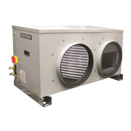
MARSTAIR DUCTED REFRIGERATION CONDENSING UNITS (DRC+)
GENERAL
54208007-06
Advertisement
Table of Contents

Related Manuals for Marstair DRC+ 30


Summary of Contents for Marstair DRC+ 30
- Page 1 The data plate only gives information for the outdoor unit. FUSES - for recommended fuse size see page 9. The refrigerant used should be identified by locating the R404A label (if appropriate) on the unit case MARSTAIR DUCTED REFRIGERATION CONDENSING UNITS (DRC+) 54208007-06...
- Page 2 INDEX CONTENTS PAGE SPECIFICATION DETAILS. DIMENSIONS & WEIGHTS. MOUNTING. PIPEWORK. ELECTRICAL & FUSES. REFRIGERANT. 9-10 RECEIVER. NOTE IF MECHANICAL PUMP DOWN OPERATION IS REQUIRED CONNECT A LINK WIRE BETWEEN TERMINALS L1 & 3. IF THIS LINK IS USED THEN TERMINAL 5 CAN NOT BE USED AS AN ALARM FACILITY 2/11 54208007-06...
-
Page 3: Specification Details
DRC+ 20 1.09 0.85 1.43 0.94 1.80 1.03 0.90 0.85 1.27 0.96 1.49 1.07 1.84 1.09 2.27 1.19 2.75 1.29 DRC+ 30 1.64 1.09 2.04 1.20 2.48 1.31 1.35 1.09 1.82 1.23 2.06 1.37 2.66 1.64 3.24 1.74 3.89 1.85 DRC+ 40 2.40... -
Page 4: Item Description
NOTE: Units are supplied with a packing piece supporting the blower assembly, this MUST be removed prior to commissioning. DIMENSION & WEIGHTS SPIGOT Model Spigot Ø Weight (kg) DRC+ 20 1004 DRC+ 30 1004 DRC+ 40 1004 DRC+ 50 1100 1174 DRC+ 60... -
Page 5: Floor Mounting
MOUNTING Ducted units are designed to be hung on a wall (brackets available as a kit), suspended from a ceiling (installer supplied fittings), or to stand on a flat surface. Whichever method is used it is essential that the mounting surface is capable of supporting the unit's weight. Leave space around the unit for air circulation and access for installation and maintenance. -
Page 6: Good Practice
DUCTWORK Each unit is supplied with air inlet and discharge spigots.(see page 2 for sizes) These may be used for connecting installers ducting or used with the optional duct, plenum and grille kits (refer to kit instructions for installation) NOTE: It is essential that ducting is adequately insulated to prevent sweating. An insulation thickness of at least 45mm is recommended. -
Page 7: Liquid Line
PIPE SIZE MAXIMUM LENGTH OF EQUIVALENT LIQUID LINE UNIT SUCTION LINE PIPE SIZES (m) SIZE ⅜ ⅝ ⅞ 1⅛ 1⅜ ⅜ ⅝ ½ ¾ ½ ¾ In calculating equivalent lengths of pipe runs, the effect of bends and fittings must be taken into account. The table below covers fittings most likely to be encountered in this type of installation. -
Page 8: Connecting The Units
CONNECTING THE UNITS Connecting the pipework: a. Remove the flare nuts from the service valves and release the nitrogen holding charge by slowly opening the valves using a 5mm or 8mm allen key. b. Ensure the suction line is fully insulated. c. - Page 9 R404A REFRIGERANT Charging the System: Evacuate the system and interconnecting pipework as page 8 ensuring the service valves are fully open. Allow the evacuated system to draw in the majority of the refrigerant charge. The final charge should be adjusted with the system running. All units are fitted with head pressure control.
- Page 10 HEAD PRESSURE CONTROL ALCO (FSY-42S) The head pressure controller is factory set to suit the refrigerant. It may be necessary to adjust this to suit site conditions, to raise or lower the nominal head pressure. a. With the system switched off, connect a high pressure gauge to the liquid line service valve. b.
- Page 11 OVER LOAD (3ph) COMPRESSOR CONTACTOR CRANK CASE HEATER FAN CAPACITOR SERVICE VALVE COMPRESSOR CAPACITOR (1ph) TEV LTD, ARMYTAGE ROAD, BRIGHOUSE, WEST YORKSHIRE, HD6 1QF. TEL: + 44 (0) 1484 405600 FAX: +44 (0) 1484 405620 EMAIL: sales@marstair.com WEB: www.marstair.com 11/11 54208007-06...
Need help?
Do you have a question about the DRC+ 30 and is the answer not in the manual?
Questions and answers