Table of Contents
Advertisement
Quick Links
FOR CD3 (929 SERIES) CHILLED WATER CLOSE CONTROL UNITS
This manual covers installation and technical aspects of TEV Ltd. CD3 range (929 series) of close control units.
INDEX
GENERAL
SELECTION
INSTALLATION
APPLICATION
WIRING DIAGRAMS
OPERATION and
COMMISSIONING
COMPONENT
IDENTIFICATION
TEV Ltd.
Armytage Road, Brighouse,
West Yorkshire. HD6 1QF.
Tel: +44 (0) 1484 40560
Fax: +44 (0) 1484 405620
e-mail: sales@marstair.com
TECHNICAL MANUAL
Introduction
General description and part numbers
- CW upflow/downflow configurable
CD3 Configurable options
Dimensions and weights
Performance data CW
Airflows
Sound levels
Airflow options
Unit mounting - Upflow
- Downflow
Pipe sizes
Electrical connections
Electrical data
Fuses
Condensate drain
Power diagram
Controls diagram
Fan speed controller
Condensate pump (optional)
Humidifier
pCONet Parameters
Microprocessor controller
Exploded views of units with
component identification
1
2
2
2
4
4
4
5
5
6
7
7
8
8
9
9
10
11
12
12
12
15
19
28
92908133-09
Advertisement
Table of Contents

Related Manuals for Marstair 929 Series


Summary of Contents for Marstair 929 Series
- Page 1 TECHNICAL MANUAL FOR CD3 (929 SERIES) CHILLED WATER CLOSE CONTROL UNITS This manual covers installation and technical aspects of TEV Ltd. CD3 range (929 series) of close control units. INDEX GENERAL Introduction General description and part numbers - CW upflow/downflow configurable...
- Page 2 INTRODUCTION The standard air handler units in the CD3 Chilled Water range are available as Configured units in upflow and downflow versions. All units are electronically controlled. Options can provide the close control of temperature and humidity demanded by computer rooms, laboratories, banks, offices etc..
- Page 3 Factory Fitted Field Fit Kit Option DESCRIPTION MODEL Part Number Part Number 008 U/D 92900423 010 U/D 92900424 LPHW COIL 7.52kW 10.50kW 015 U/D 92900424 14.94kW 18.40kW 020 U/D 92900425 92900426 LPHW VALVE 2 WAY (motorised) 3 WAY 92900427 HUMIDIFIER 0-4kg/h 008U 92900444...
-
Page 4: Product Selection
CD3 UNITS DIMENSIONS AND WEIGHTS (no plenums fitted) UNPACKED PACKED Model HEIGHT mm 1165 1165 1165 1165 1300 1300 1300 1300 WIDTH mm 1230 1380 1380 1580 1250 1400 1400 1600 DEPTH mm WEIGHT kg PRODUCT SELECTION CHILLED WATER PERFORMANCE DATA MODEL 1.51 AIRFLOW (max) m... - Page 5 SOUND PRESSURE LEVELS -- CD3 UNITS UPFLOW FAN SPEED Top Discharge and Front Return High 66.5 Front Discharge with Plenum and Front Return High 58.5 58.5 Front Discharge and Front Return High DOWNFLOW FAN SPEED Standard High CD3 AIRFLOW OPTIONS...
- Page 6 CD3 SERIES CLOSE CONTROL UNIT INSTALLATION An envelope containing important user information is supplied with the indoor unit. Please pass this to the end user. 1 The standard unit is supplied configured for the correct airflow as ordered by the customer. 2 The central panel, with control panel inset, MUST be removed first using the two keys provided.
-
Page 7: Pipe Connections
DOWNFLOW SERVICE AND FIXING HOLE CENTRES UNIT DIMENSION 'A' DIMENSION 'B' 1230 010/015 1380 1580 4 If a fresh air facility is required, apertures must be prepared as shown above/opposite. This must be suitably lined and screened on the internal wall to prevent brick dust entering the unit. 5 Mount the unit and secure the fixings. -
Page 8: Electrical Connections
ELECTRICAL CONNECTIONS The installation wiring should be carried out in accordance with I.E.E. regulations and/or local codes. A mains isolator should be used and the system suitably fused, (see page 24). Supply cables and connecting cables are provided by the installer. INDOOR UNIT WIRING Connections for internal wiring are made within the electrics enclosure accessed by removing the centre front cover. -
Page 9: Current Ratings
CURRENT RATINGS CD3 HEATING (1 PHASE UNIT SIZE TOTAL CURRENT HEATING RATING LOAD (Amps) 1 STAGE 2 STAGE 1 STAGE 2 STAGE 1 STAGE 2 STAGE 1 STAGE 2 STAGE 16.7 O (2+2) O (2+2) O (2+2) O (2+2) O (4+2) O (4+2) O (4+2) O (4+2) -
Page 10: Power Wiring Diagram
POWER WIRING DIAGRAM... -
Page 11: Control Wiring Diagram
CONTROL WIRING DIAGRAM For HUMIDIFIER wiring diagram see page 13. -
Page 12: Fan Speed Controller
FAN SPEED CONTROLLER One control is used on eachCD3 unit, and has a switch for selecting high or boost speed (see diagram below). These can only be selected if the Pico Controller is set at low. SETTING The boost speed should be selected for:- ... -
Page 13: Installation
DESCRIPTION The humidifier is an electrode steam boiler, electronically controlled. The steam bottle requires changing periodically. The humidifier is fitted with a bottle change indication and the frequency of change is dependent upon the condition of the water feeding the humidifier. INSTALLATION Water supply The humidifier operates with a range of water qualities;... -
Page 14: Humidifier Start Up
Jumper Positions With Jumper Without Jumper Connection to a mains supply with ground fault Connection to a mains supply without ground fault circuit interrupter circuit interrupter * Increased drain operation factor Regular drain operation factor * Normal water conductivity (≤125 µS/cm) * Low water conductivity (<125 µS/cm) Exchangeable steam cylinder * Cleanable steam cylinder... - Page 15 Connect pCOnet via RS485 to a computer: during configuration, the CAREL RS485 converter (CVSTDMOR0) for USB ports can be used, Marstair part number 92919136. USB converters should not be used in the installation due to the large volume of data transmitted across a complex BACnet network.
- Page 16 Digital Variables Address Description Type Communication type Compressor 1 general alarm digital input Digital Reading Compressor 2 general alarm digital input Digital Reading ON/OFF remote Digital Reading fire / smoke alarm digital input Digital Reading Dehumidification Digital Reading ON /OFF unit Digital Reading 3p cold valve opening contact (CW) / Cooling 1 DX...
- Page 17 Analog Variables Address Description Type Communication type Ambient temperature Analog Reading Ambient humidity Analog Reading Supply air temperature Analog Reading Dead zone in temperature Analog Writing / Reading Ambient humidity band Analog Writing / Reading Ambient humidity set Analog Writing / Reading Low temperature alarm offset Analog Writing / Reading...
- Page 18 GENERAL MAINTENANCE 12 MONTHLY (or more frequently if conditions dictate) Clean the feed water strainer and drain solenoid valve. Check hoses for wear and flush out the drain tube. Check all electrical connections are tight. Check and clean the drain tray to prevent a build up of deposit UNIT OPERATING INSTRUCTIONS DESCRIPTION OF CONTROLS All CD3 units are fitted with a microprocessor controller and a display and keypad mounted on the front of the unit,...
-
Page 19: Keypad Functions
00:00 00/00/00 Unit 1 Temperature 00.0 °C Humidity 00.0% Unit On Display and keypad KEYPAD FUNCTIONS FUNCTION FUNCTION Displays measured Setting of operating values. parameters and safety Returns operator to the thresholds. main mask window. Displays the version of the Displays working hours and application programme loaded allows counter re-set. - Page 20 When the unit is first powered up the display will show; SELF TEST - PLEASE WAIT. Once the self test has been completed the MAIN MASK will be displayed. This is the default screen. Current time Date Mask Number 00:00 00/00/00 M:01 Actual Temperature...
- Page 21 AUTO RESTART AFTER BLACKOUT ENABLE REMOTE ON/OFF NEW USER PASSWORD 0000 ENGINEERING LEVEL ACCESS (Password required) PROGRAMME BUTTON MENU SERVICE Press PASSWORD 0000 LIMITS SET POINT TEMPERATURE: 15°C 30°C LIMITS SET POINT HUMIDITY TEMPERATURE COOL DIFFER. 1.0°C HEAT DIFFER. 1.0°C DEAD BAND 0.5°C HUMIDITY...
- Page 22 SEL. TYPE ALARM S = SERIOUS N = NOT SERIOUS AL01: NNNNS AL06: NNNS AL10: NSSSS AL15: NNNN SEL. TYPE ALARM S = SERIOUS N = NOT SERIOUS AL19: NSNNN AL24: SNNN AL28: NNNNN AL33: NNSN SEL. TYPE ALARM S = SERIOUS N = NOT SERIOUS AL37: N---- AL42: ----...
- Page 23 CLOCK BUTTON MENU REGULATION CLOCK HOUR 00:00 Press DATE 00/00/00 MONDAY SERVICE PASSWORD 0000 ENABLE AUTOMATIC TEMPERATURE SET POINT VARIATION TEMPERATURE TIME ZONE N.1 START HOUR 00:00 SET POINT 00.0°C TEMPERATURE TIME ZONE N.2 START HOUR 00:00 SET POINT 00.0°C TEMPERATURE TIME ZONE N.3 START HOUR...
- Page 24 HUMIDITY TIME ZONE N.2 START HOUR 00:00 SET POINT 000.0% HUMIDITY TIME ZONE N.3 START HOUR 00:00 SET POINT 000.0% HUMIDITY TIME ZONE N.4 START HOUR 00:00 SET POINT 000.0% Press to return to the MAIN MASK INPUT /OUTPUT BUTTON MENU ANALOGUE INPUTS Press RETURN AIR TEMPERATURE...
- Page 25 MAINTENANCE BUTTON MENU WORK HOURS Press 000000 COMPRESSOR 1 000000 COMPRESSOR 2 000000 HISTORY ALARM AL00 00:00 00/00/00 SET T: 00.0 T: 00.0 SET H : 000.0 H: 000.0 SERVICE PASSWORD 0000 H. THRESHOLD 100 x 1000 RESET No 000000 COMPRESSOR 1 H.
- Page 26 The manual operating procedure may only be activated when the unit is in standby mode. In this mode the ON/OFF button is in the OFF position. MANUAL PROCEDURE MAIN FAN ENERGY SAVING MANUAL PROCEDURE DE-HUMIDIFIER HUMIDIFIER MANUAL PROCEDURE COMP 1 / CW OPEN COMP 2 / CW CLOSE MANUAL PROCEDURE HEAT 1 / LPHW OPEN...
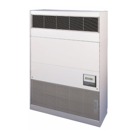
- Page 27 Note: The position of some of the controls shown in this diagram may vary from those in the unit delivered. Coil Filter Electrics access Drain tray Transformer Washable filter Access panel Discharge grille Return air grille Terminal Relay Humidity sensor Contactor Fan speed control Isolator...
Need help?
Do you have a question about the 929 Series and is the answer not in the manual?
Questions and answers