Table of Contents
Advertisement
Quick Links
Download this manual
See also:
User Manual
Advertisement
Table of Contents

Related Manuals for Kramer VP-445


Summary of Contents for Kramer VP-445
- Page 1 USER MANUAL MODEL: VP-445 Presentation Switcher/Scaler P/N: 2900-300502 Rev 4 www.kramerAV.com...
-
Page 2: Table Of Contents
Microphone Pinout Controlling the VP-445 Controlling via the Front Panel Buttons Using the OSD Menu Connecting to the VP-445 via RS-232 Operating via Ethernet Using the Infrared Remote Control Transmitter Using the Embedded Web Pages Browsing the VP-445 Web Pages... -
Page 3: Introduction
Kramer Electronics Ltd. Introduction Welcome to Kramer Electronics! Since 1981, Kramer Electronics has been providing a world of unique, creative, and affordable solutions to the vast range of problems that confront video, audio, presentation, and broadcasting professionals on a daily basis. In recent years, we have... -
Page 4: Overview
European Advanced Recycling Network (EARN) and will cover any costs of treatment, recycling and recovery of waste Kramer Electronics branded equipment on arrival at the EARN facility. For details of Kramer’s recycling arrangements in your particular country go to our recycling pages at www.kramerav.com/support/recycling/. - Page 5 Front panel control – audio mute and freeze frame. • Front panel lockout. • Non-volatile memory – saves final settings. Control your VP-445: • Directly, via the front panel push buttons. • By RS-232 serial commands transmitted by a touch screen system, PC, or other serial controller.
-
Page 6: Defining The Vp-445 Presentation Switcher/Scaler
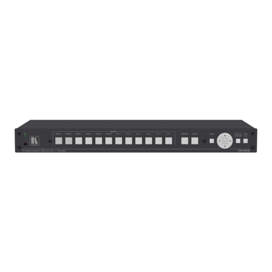
Kramer Electronics Ltd. Defining the VP-445 Presentation Switcher/Scaler This section defines the VP-445. Figure 1: VP-445 Presentation Switcher/Scaler Front Panel Feature Function IR LED Lights when the unit accepts IR remote commands IR Receiver Receives signals from the remote control transmitter... - Page 7 Kramer Electronics Ltd. Figure 2: VP-445 Presentation Switcher/Scaler Rear Panel Feature Function 12 VIDEO INPUT HDMI Connects to an HDMI source (from 1 to 6) Connectors PC 15-pin HD Connects to a computer graphics source (from 1 to 4) CV RCA...
-
Page 8: Mounting Vp-445
Kramer Electronics Ltd. Mounting VP-445 This section provides instructions for mounting VP-445. Before installing, verify that the environment is within the recommended range: • Operation temperature – 0 to 40C (32 to 104F). • Storage temperature – -40 to +70C (-40 to +158F). -
Page 9: Connecting The Vp-445
Kramer Electronics Ltd. Connecting the VP-445 Always switch off the power to each device before connecting it to your VP-445. After connecting your VP-445, connect its power and then switch on the power to each device. You do not have to connect all the inputs and outputs, connect only those that are required. -
Page 10: Connecting The Balanced Stereo Audio Output
Figure 8. Connect the power cord (not shown in Figure 9. If required, connect: ▪ A PC via RS-232, see Connecting to the VP-445 via RS-232 on page ▪ The ETHERNET port, see Operating via Ethernet on page Connecting the Balanced Stereo Audio Output... -
Page 11: Controlling The Vp-445
Using the OSD Menu on page 9) • RS-232 serial commands transmitted by a touch screen system, PC, or other serial controller (see Connecting to the VP-445 via RS-232 on page 12) • The Ethernet (see Operating via Ethernet on page 13) •... - Page 12 AUTOMATIC: the embedded audio on the HDMI input is selected for an HDMI signal, or the analog audio input is selected if the input is not HDMI (for example, for a DVI input signal) EMBEDDED: the embedded audio in the HDMI signal is selected VP-445 – Controlling the VP-445...
- Page 13 This is useful, for example, when the output is connected to a projector, and the projector automatically shuts down when it has no input H POSITION Set the horizontal position of the OSD V POSITION Set the vertical position of the OSD VP-445 – Controlling the VP-445...
-
Page 14: Connecting To The Vp-445 Via Rs-232
INFORMATION Displays the INPUT and OUTPUT RESOLUTION, INPUT and OUTPUT HDCP, the firmware version and the IP ADDRESS Connecting to the VP-445 via RS-232 You can connect to the VP-445 via an RS-232 connection using, for example, a PC. Note that a null-modem adapter/connection is not required. -
Page 15: Operating Via Ethernet
The Local Area Connection Properties window for the selected network adapter appears as shown in Figure Figure 9: Local Area Connection Properties Window 4. Highlight either Internet Protocol Version 6 (TCP/IPv6) or Internet Protocol Version 4 (TCP/IPv4) depending on the requirements of your IT system. VP-445 – Controlling the VP-445... - Page 16 6. Select Use the following IP Address for static IP addressing and enter the details as shown in Figure For TCP/IPv4 you can use any IP address between 192.168.1.1 to 192.168.1.255 (excluding 192.168.1.39) that is provided by your IT department. VP-445 – Controlling the VP-445...
- Page 17 You can connect the Ethernet port of the VP-445 to the Ethernet port on a network hub or using a straight-through cable with RJ-45 connectors. Configuring the Ethernet Port You can set the Ethernet parameters via the embedded Web pages. VP-445 – Controlling the VP-445...
-
Page 18: Using The Infrared Remote Control Transmitter
EXIT the menu FREEZE Freeze/unfreeze the output video image Panel Lock/unlock the front panel buttons Lock MUTE Toggle between muting (blocking out the sound) and enabling the audio output Figure 13: Infrared Remote Control Transmitter VP-445 – Controlling the VP-445... -
Page 19: Using The Embedded Web Pages
To browse the VP-445 Web pages: 1. Open your Internet browser. 2. Type the IP address of the device in the Address bar of your browser. For example, the default IP address: The Input Select Web page appears. VP-445 – Using the Embedded Web Pages... -
Page 20: Input Select Page
When in standby mode, the icon appears dim: Figure 15: VP-445 Standby Mode To edit an input button, select that button and click the edit icon ( ). The input edit window appears: VP-445 – Using the Embedded Web Pages... - Page 21 Click the exit icon ( ) to exit the window. Figure 17 shows the PC and CV edit window. Click the exit icon ( ) to exit the window. Figure 17: PC and CV Input Edit Window VP-445 – Using the Embedded Web Pages...
-
Page 22: Device Settings Page
Figure 19: Device Settings Page – Static IP Confirmation. Firmware Upgrade To upgrade the firmware via the Device Settings page: 1. In the Firmware update field click the Choose File button to choose the firmware file. 2. Click the Upgrade button. VP-445 – Using the Embedded Web Pages... - Page 23 4. After restarting the system upload the Web page once again. 5. Verify that the new version appears on the lower left corner of the Web page: Figure 22: Device Settings Page – New Firmware Updated VP-445 – Using the Embedded Web Pages...
-
Page 24: Output Settings Page
Output Settings page: Figure 23: Output Settings Page The output settings include the Resolution and Size of the image, the picture settings, and the Finetune items (which are enabled for VGA inputs). VP-445 – Using the Embedded Web Pages... -
Page 25: Hdcp Page
The HDCP page lets you set the HDCP on the output (follow input or follow output) and the HDCP status for each of the HDMI inputs. Figure 24 shows the HDCP page: Figure 24: HDCP Page VP-445 – Using the Embedded Web Pages... -
Page 26: Edid Page
Native Timing list and select one or more inputs. To copy, click the Copy button: Figure 26: EDID Page – Copying a Selected Input Resolution The EDID page displays the machine name, selected resolution, audio channels and deep color support. VP-445 – Using the Embedded Web Pages... - Page 27 In the same way you can read the EDID from one of the outputs. To do so, select an output and click Copy: Figure 28: EDID Page – Copying EDID from an Output VP-445 – Using the Embedded Web Pages...
-
Page 28: Audio Page
(Off), set the auto switching to Off, Auto Scan or HDMI Last connected, set the input priority to PC or HDMI (once the auto scan is enabled), and set the Lock Mode, see Figure Figure 30: Advanced Page VP-445 – Using the Embedded Web Pages... -
Page 29: Rs-232 Page
RS-232 controlled device. Figure 31: RS-232 Page To control an external device via VP-445: 1. Connect the RS-232 port on the VP-445 to the RS-232 port of an external device (for example, a projector connected to HDMI™... -
Page 30: About Page
Kramer Electronics Ltd. About Page VP-445 About page lets you view the Web page version and Kramer Electronics Ltd details. Figure 34: About Page VP-445 – Using the Embedded Web Pages... -
Page 31: Technical Specifications
10% to 90%, RHL non-condensing Physical Dimensions 19" x 7" x 1U (W, D, H) rack mountable Weight 1.8kg (4lbs) approx. Accessories Included Power cord, rack ears, IR remote control Specifications are subject to change without notice at www.kramerav.com VP-445 – Technical Specifications... -
Page 32: Default Communication Parameters
Example (Route the video HDMI3 input to #ROUTE 1,1,3<cr> the output ports): Input Resolutions Resolution/Refresh Rate Composite HDMI 480I/576I 480P/576P 720P@(50/60) 1080I@(50/60) 1080P@(50/60) 1080P@(24/25/30) VGA@(60/67/72/75/85) SVGA@(56/60/72/75) XGA@(60/70/75) SXGA@(60/75) 1280X960@60 1280x720@60 1920X1080@60 UXGA@60(1600X1200 ) WXGA@60(1280x800) WXGA+@60(1440x900) WXGA@60(1366x768) SXGA+@60(1400x1050) 1600X900@60 RB WSXGA@60 RB(1680x1050 RB) VP-445 – Technical Specifications... -
Page 33: The Rs-232/Ethernet (Tcp) Communication Protocol
You can enter commands directly using terminal communication software (e.g., Hercules) by connecting a PC to the serial or Ethernet port on the VP-445. To enter CR press the Enter key (LF is also sent but is ignored by the command parser). -
Page 34: Understanding Protocol 3000
A separate response is sent for every command in the chain. • Kramer Protocol 3000 Syntax on page • Protocol 3000 commands available for the VP-445, see Protocol 3000 Commands on page Understanding Protocol 3000 Protocol 3000 commands are structured according to the following: •... -
Page 35: Kramer Protocol 3000 Syntax
Kramer Electronics Ltd. Kramer Protocol 3000 Syntax The Kramer Protocol 3000 syntax uses the following delimiters: • CR = Carriage return (ASCII 13 = 0x0D) • LF = Line feed (ASCII 10 = 0x0A) • SP = Space (ASCII 32 = 0x20) Some commands have short name syntax in addition to long name syntax to enable faster typing. - Page 36 – Format: YYYY/MM/DD where YYYY = Year, MM = Month, DD = Day time – Format: hh:mm:ss where hh = hours, mm = minutes, ss = seconds K-Config Example Read the device build date: “#BUILD-DATE?”,0x0D VP-445 – The RS-232/Ethernet (TCP) Communication Protocol...
- Page 37 1. Multi-line: ~nn@Device available protocol 3000 commands:CR LFcommand,SP command...CR LF 2. Multi-line: ~nn@HELPSPcommand:CR LFdescriptionCR LFUSAGE:usageCR LF Parameters COMMAND_NAME – name of a specific command Notes To get help for a specific command use: HELPSPCOMMAND_NAMECR LF K-Config Example “#HELP”,0x0D VP-445 – The RS-232/Ethernet (TCP) Communication Protocol...
- Page 38 Get: End User Public Description Syntax Set: #PROT-VER?CR Get: Get protocol version Response ~nn@PROT-VERSP3000:versionCR LF Parameters Version – Format: XX.XX where X is a decimal digit K-Config Example Get the protocol version: “#PROT-VER?”,0x0D VP-445 – The RS-232/Ethernet (TCP) Communication Protocol...
- Page 39 Transparency Set: Get: End User Public Description Syntax Set: #SN?CR Get: Get device serial number Response ~nn@SNSPserial_numberCR LF Parameters serial_number – 14 decimal digits, factory assigned K-Config Example Get device serial number: “#SN?”,0x0D VP-445 – The RS-232/Ethernet (TCP) Communication Protocol...
- Page 40 Response is sent after every change in output HPD status OFF to ON and ALL parameters (new EDID, etc.) are stable and valid K-Config Example Get the output HPD status of HDMI 1: “#DISPLAY? 1”,0x0D VP-445 – The RS-232/Ethernet (TCP) Communication Protocol...
- Page 41 End User System Description Syntax #LOCK-FPSPP1CR Set: Lock front panel #LOCK-FP?CR Get: Get front panel lock state Response nn@LOCK-FPSPP1SPOKCR LF Parameters P1 – 0 (No) 1 (Yes) K-Config Example Lock front panel: “#LOCK-FP 1”,0x0D VP-445 – The RS-232/Ethernet (TCP) Communication Protocol...
- Page 42 Description Syntax #ROUTESPParamCR Set: Set menu navigation Get: Response ~ nn@MENU_CMDSPParamCR LF Parameters Param – Menu=1, Enter=2, Up=4, Down=5, Right=6, Left=7) Notes This command emulates menu navigation K-Config Example Select menu: “#MENU-CMD 1”,0x0D VP-445 – The RS-232/Ethernet (TCP) Communication Protocol...
- Page 43 “Get” command with is_native=ON returns native resolution VIC, with is_native=OFF returns current resolution To use “custom resolutions” (entries 100-105), define them using command DEF-RES K-Config Example Set video resolution on output to 1360x768 @60Hz: “#VID-RES 1,1,0,204”,0x0D VP-445 – The RS-232/Ethernet (TCP) Communication Protocol...
- Page 44 Get freeze on output status Response Set / Get: ~nn@VFRSPP1,P2CR LF Parameters P1 – 1 (Scaler) P2 – freeze status: 0 (Off), 1 (On) K-Config Example Set freeze video output to off: “#TREBLE 1,0”,0x0D VP-445 – The RS-232/Ethernet (TCP) Communication Protocol...
- Page 45 After execution, response is sent to all com ports if CMD-NAME was set any other external control device (button press, device menu and similar) or genlock status was changed Notes Sets the image properties of the selected scaler K-Config Example Set the image size to PanScan: “#IMAGE-PROP 1,3”,0x0D VP-445 – The RS-232/Ethernet (TCP) Communication Protocol...
- Page 46 SCLR-AUDIO-DELAY Set/get the scaler audio delay MIC-GAIN Set/get the microphone gain Set/get the talkover mode status MIC-TLK Set/get the microphone talkover mode status MIC-SELECT Select/get the microphone STANDBY Set/get the standby mode status VP-445 – The RS-232/Ethernet (TCP) Communication Protocol...
- Page 47 Note that you can choose an input channel or the output, based on the selected P1. P3 – 0-100 (audio level) minus sign precedes negative values. ++ increase current value, -- decrease current value K-Config Example Set the HDMI 45 input AUD-LVL to 75: “#AUD-LVL 0,3,75”,0x0D VP-445 – The RS-232/Ethernet (TCP) Communication Protocol...
- Page 48 After execution, response is sent to all com ports if AUD-EMB was set by any other external control device (button press, device menu and similar) K-Config Example Embed HDMI input 1 audio: “#AUD-EMB 0,0,1”,0x0D VP-445 – The RS-232/Ethernet (TCP) Communication Protocol...
- Page 49 Response ~nn@BASSSPchannel,bass_levelCR LF Parameters channel – 1 (scaler) bass_level – 0-30 (value) audio parameter in Kramer units, minus sign precedes negative values ++ increase current value -- decrease current value K-Config Example Set the bass level to 15: “#BASS 1,15”,0x0D...
- Page 50 Response ~nn@TREBLESPchannel,treble_levelCR LF Parameters channel – 1 (scaler) treble_level – 0-30 (value) audio parameter in Kramer units, minus sign precedes negative values ++ increase current value -- decrease current value K-Config Example Set the audio treble level to 25: “#TREBLE 1,25”,0x0D...
- Page 51 (button press, device menu and similar) or genlock status was changed Notes Sets the Auto Sync features for the selected Scaler K-Config Example Set the auto sync off timer to slow: “#SCLR-AS 1,2”,0x0D VP-445 – The RS-232/Ethernet (TCP) Communication Protocol...
- Page 52 After execution, response is sent to all com ports if CMD-NAME was set any other external control device (button press, device menu and similar) or genlock status was changed Notes Sets the audio delay for the selected audio output K-Config Example Set the scaler audio delay to 40ms: “#SCLR-AUDIO-DELAY 1,1”,0x0D VP-445 – The RS-232/Ethernet (TCP) Communication Protocol...
- Page 53 Response ~nn@TLKSPchannel,talkover_modeCR LF Parameters channel – 1 ( Scaler) talkover_mode – 0 (Off), 1 (Mixer), 2 (Talkover), 3 (Mic only) K-Config Example Set the scaler audio talkover mode to Mic only: “#TLK 1,3”,0x0D VP-445 – The RS-232/Ethernet (TCP) Communication Protocol...
- Page 54 Set: #MIC- SELECT?SPP1CR Get the microphone Get: Response ~nn@MIC- SELECTSPp1,p2CR LF Parameters P1 –scaler=1 P2 – Mic mode OFF=[], MIC1= , MIC2= , Both=[ ], [ K-Config Example Select microphone 1: “#MIC-SELECT 1,1”,0x0D VP-445 – The RS-232/Ethernet (TCP) Communication Protocol...
- Page 55 Communication Description Syntax Set: #NET-MAC?CR Get: Get MAC address Response ~nn@NET-MACSPmac_addressCR LF Parameters mac_address – Unique MAC address. Format: XX-XX-XX-XX-XX-XX where X is hex digit. K-Config Example Get the MAC address: “#NET-MAC? XX-XX-XX-XX-XX-XX”,0x0D VP-445 – The RS-232/Ethernet (TCP) Communication Protocol...
- Page 56 A network gateway connects the device via another network and maybe over the Internet. Be careful of security problems. For proper settings consult your network administrator K-Config Example Set the gateway IP address to 192.168.0.1: “#NET-GATE 192.168.000.001”,0x0D VP-445 – The RS-232/Ethernet (TCP) Communication Protocol...
- Page 57 “NAME”. You can also get an assigned IP by direct connection to USB or RS-232 protocol port if available. For proper settings consult your network administrator. K-Config Example Set the DHCP mode to static: “#NET-DHCP 0”,0x0D VP-445 – The RS-232/Ethernet (TCP) Communication Protocol...
- Page 58 Set Ethernet port protocol #ETH-PORT?SPporttypeCR Get: Get Ethernet port protocol Response Set: ~nn@ ETH-PORT SPporttype,ethportCR LF Parameters porttype – TCP=0 ethport – 1 to 65535 K-Config Example Set TCP to 2: “#ETH-PORT 0,2”,0x0D VP-445 – The RS-232/Ethernet (TCP) Communication Protocol...
-
Page 59: Kramer Protocol 3000 -Command Keys
720p @60Hz 1360x768 @60Hz 1080i @60Hz 1280x720 @60Hz 1080p @60Hz 1280x800 @60Hz 576p @50Hz 1280x1024 @60Hz 720p @50Hz 1440x900 @60Hz 1080i @50Hz 1400x1050 @60Hz 1080p @50Hz 1680x1050 @60Hz NATIVE OUT1 1600x1200 @60Hz NATIVE OUT2 VP-445 – The RS-232/Ethernet (TCP) Communication Protocol... - Page 60 Electronics products, this product must be insured during shipment, with the insurance and shipping charges prepaid by you. If this product is returned uninsured, you assume all risks of loss or damage during shipment. Kramer Electronics will not be responsible for any costs related to the removal or re- installation of this product from or into any installation.
- Page 61 SAFETY WARNING Disconnect the unit from the power supply before opening and servicing For the latest information on our products and a list of Kramer distributors, visit our Web site where updates to this user manual may be found. We welcome your questions, comments, and feedback.
Need help?
Do you have a question about the VP-445 and is the answer not in the manual?
Questions and answers