Kramer VP-440 Quick Start Manual
Presentation switcher/scaler
Hide thumbs
Also See for VP-440:
- User manual (65 pages) ,
- Quick start manual (2 pages) ,
- User manual (61 pages)
Advertisement
Quick Links
VP-440 Quick Start Guide
This guide helps you install and use your product for the first time. For more detailed information, g
to
http://www.kramerav.com/manual/VP-440
the left.
Step 1: Check what's in the box
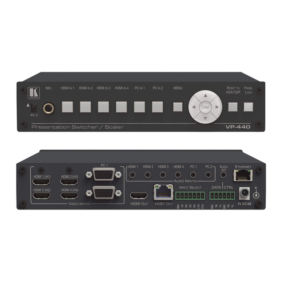
VP-440
The
Presentation Switcher/Scaler
1 Power adapter
Mounting brackets
Step 2: Install the VP-440
Mount the machine in a rack or place on a table.
Step 3: Connect inputs and outputs
BluRay Disk
Player
For best results, we recommend that you always use Kramer high-performance cables to connect AV equipment to
the VP-440.
RJ-45 Pinout
For the Ethernet connector, see the proper wiring diagram below:
PIN
1
2
3
4
5
6
7
8
For optimum range and performance use Kramer's BC-HDKat6a
cable. These specially built cables significantly outperform
regular CAT 6 cables.
VP-440 Quick Start (P/N: 2900-300476QS REV 1)
Microphone
Analog Audio
Inputs
Computer
Laptop
Graphics
Source (PC)
EIA / TIA 568B
Wire Color
Orange / White
Orange
Green / White
Blue
Blue / White
Green
Brown / White
Brown
to download the latest manual or scan the QR code on
4 Rubber feet
1 Quick start guide
Always switch OFF the power on each device
before connecting it to your VP-440.
LCD
Projector
Display
PC Control
Device
The Microphone Pinout:
For a condenser
microphone:
For a dynamic
microphone:
Analog Audio
Inputs
Rev:
2 9 0 0 - 3 0 0 4 7 6 QS
o
Microphone +
Microphone -
Ground
Microphone
Ground
Rev:
1
Advertisement

Related Manuals for Kramer VP-440


Summary of Contents for Kramer VP-440
- Page 1 Display Source (PC) PC Control Device For best results, we recommend that you always use Kramer high-performance cables to connect AV equipment to the VP-440. RJ-45 Pinout The Microphone Pinout: For the Ethernet connector, see the proper wiring diagram below:...
- Page 2 Step 4: Connect the power Connect the 5V DC power adapter to the rear of the VP-440 and connect the adapter to the mains electricity Step 5: Set operation parameters via OSD menu Menu Item Function Enter the OSD menu via the MENU button...
Need help?
Do you have a question about the VP-440 and is the answer not in the manual?
Questions and answers