Table of Contents
Advertisement
Quick Links
Download this manual
See also:
User Manual
Advertisement
Table of Contents

Subscribe to Our Youtube Channel
Related Manuals for Kramer VP-444


Summary of Contents for Kramer VP-444
- Page 1 USER MANUAL MODEL: VP-444 Presentation Switcher/Scaler P/N: 2900-300305 Rev 9 www.kramerAV.com...
-
Page 2: Table Of Contents
Overview Defining VP-444 Presentation Switcher/Scaler Mounting VP-444 Connecting VP-444 Connecting Balanced Stereo Audio Output Microphone Pinout Connecting to VP-444 via RS-232 Operating VP-444 Using Front Panel Buttons Using OSD Menu Operating via Ethernet Controlling via Infrared Remote Control Transmitter Using Embedded Web Pages... -
Page 3: Introduction
Kramer Electronics Ltd. Introduction Welcome to Kramer Electronics! Since 1981, Kramer Electronics has been providing a world of unique, creative, and affordable solutions to the vast range of problems that confront the video, audio, presentation, and broadcasting professional on a daily basis. In recent years, we have redesigned and upgraded most of our line, making the best even better! Congratulations on purchasing your Kramer VP-444 Presentation Switcher/Scaler. -
Page 4: Overview
European Advanced Recycling Network (EARN) and will cover any costs of treatment, recycling and recovery of waste Kramer Electronics branded equipment on arrival at the EARN facility. For details of Kramer’s recycling arrangements in your particular country go to our recycling pages at www.kramerav.com/support/recycling. - Page 5 • Via the Ethernet with built-in Web pages. The VP-444 is housed in a 19” 1U rack mountable enclosure, with rack “ears” included, and is fed from a 100-240 VAC universal switching power supply. For optimum range and performance use the recommended Kramer shielded twisted pair cables available at www.kramerav.com/product/VP-444.
-
Page 6: Defining Vp-444 Presentation Switcher/Scaler
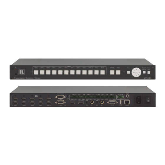
Kramer Electronics Ltd. Defining VP-444 Presentation Switcher/Scaler This section defines the VP-444. Figure 1: VP-444 Presentation Switcher/Scaler Front Panel Feature Function IR LED Lights when the unit accepts IR remote commands IR Receiver Receives signals from the remote control transmitter... - Page 7 Kramer Electronics Ltd. Figure 2: VP-444 Presentation Switcher/Scaler Rear Panel Feature Function VIDEO INPUT HDMI Connect to the HDMI source (from 1 to Connectors PC 15-pin HD Connect to the computer graphics source (from 1 to 2) AUDIO INPUT HDMI...
-
Page 8: Mounting Vp-444
Kramer Electronics Ltd. Mounting VP-444 This section provides instructions for mounting VP-444. Before installing, verify that the environment is within the recommended range: • Operation temperature – 0 to 40C (32 to 104F). • Storage temperature – -40 to +70C (-40 to +158F). -
Page 9: Connecting Vp-444
Kramer Electronics Ltd. Connecting VP-444 Always switch off the power to each device before connecting it to your VP-444. After connecting your VP-444, connect its power and then switch on the power to each device. Figure 3: Connecting the VP-444 Presentation Switcher / Scaler You do not have to connect all the inputs and outputs, connect only those that are required. -
Page 10: Connecting Balanced Stereo Audio Output
The microphone 6mm jack pinout for a Dynamic microphone. Figure 7: Dynamic Microphone Pinout Connecting to VP-444 via RS-232 You can connect to the VP-444 via an RS-232 connection using, for example, a PC. Note that a null-modem adapter/connection is not required. VP-444 – Connecting VP-444... - Page 11 Kramer Electronics Ltd. To connect to the VP-444 via RS-232, connect the RS-232 9-pin D-sub rear panel port on the product unit via a 9-wire straight cable (only pin 2 to pin 2, pin 3 to pin 3, and pin 5 to pin 5 need to be connected) to the RS-232 9-pin D-sub port on your PC VP-444 –...
-
Page 12: Operating Vp-444
Controlling via Infrared Remote Control Transmitter on page 17). Using Front Panel Buttons The VP-444 includes the following front panel buttons: • Input selector buttons for selecting the required input: HDMI (1 to 10) and PC (1 and 2). •... -
Page 13: Using Osd Menu
The front panel buttons can also be locked via the Advanced webpage (see Defining Panel Lock Button on page 31). Using OSD Menu The control buttons let you control the VP-444 via the OSD menu. Press: • MENU to enter the menu. The default timeout is set to 10 seconds. •... - Page 14 Hold Time period MIC GAIN BOOST – set to ON or OFF. Some versions of the VP-444 include this selection. In the case that the setting selected is not supported...
- Page 15 Lock the MENU (and navigation) front panel buttons only ALL & SAVE Lock all the front panel buttons. The lock status is saved when the VP-444 is powered down MENU ONLY & Lock the MENU (and navigation) front panel buttons SAVE only.
-
Page 16: Operating Via Ethernet
Connecting the Ethernet Port Directly to a PC You can connect the Ethernet port of the VP-444 directly to the Ethernet port on your PC using a crossover cable with RJ-45 connectors. This type of connection is recommended for identifying the VP-444 with the factory configured default IP address. - Page 17 4. Highlight either Internet Protocol Version 6 (TCP/IPv6) or Internet Protocol Version 4 (TCP/IPv4) depending on the requirements of your IT system. 5. Click Properties. The Internet Protocol Properties window relevant to your IT system appears. Figure 9: Internet Protocol Version 4 Properties Window VP-444 – Operating VP-444...
- Page 18 8. Click Close. Connecting the Ethernet Port via a Network Hub or Switch You can connect the Ethernet port of the VP-444 to the Ethernet port on a network hub or using a straight-through cable with RJ-45 connectors. Configuring the Ethernet Port You can set the Ethernet parameters via the embedded Web pages.
-
Page 19: Controlling Via Infrared Remote Control Transmitter
Kramer Electronics Ltd. Controlling via Infrared Remote Control Transmitter You can control the VP-444 from the infrared remote control transmitter: Keys Function POWER Toggle the power save mode ON or OFF HDMI Select the HDMI input (from 1 to 10) -
Page 20: Using Embedded Web Pages
Kramer Electronics Ltd. Using Embedded Web Pages The VP-444 can be operated remotely using the embedded Web pages. The Web pages are accessed using a Web browser and an Ethernet connection. Before attempting to connect: • Perform the procedures in... -
Page 21: Loading And Saving Configurations
3. Click the tabs on the left side of the screen to access the relevant web page. Loading and Saving Configurations VP-444 enables you to save a configuration for easy recall in the future. Saving Configurations To save the current configuration: 1. -
Page 22: Entering Standby Mode
The device is configured according to the saved preset. Entering Standby Mode VP-444 features a power saving standby mode that consumes less power without having to power off. Standby mode puts the device in a low power consumption mode without turning it off. - Page 23 Embedded – The embedded audio in the HDMI signal is selected. 6. Adjust the volume using the slider or entering a value. 7. Upon completion, save the changes ( ) and click the exit icon ( ). VP-444 – Using Embedded Web Pages...
-
Page 24: Selecting Input To Be Switched To Outputs
1. Click Input Select on the Navigation List. The Input Select page appears (Figure 13). 2. Use the slider controls in the Volume area of the web page. 3. Click to mute the output. VP-444 – Using Embedded Web Pages... -
Page 25: Configuring Network Settings
Kramer Electronics Ltd. Configuring Network Settings VP-444 enables you to use DHCP mode or to turn DHCP mode off and change network settings. To configure network settings: 1. Click Device Settings on the Navigation List. The Device Settings page appears. -
Page 26: Upgrading Firmware
Figure 20: Device Settings Page – Uploading the New Firmware File 5. Once the file is uploaded follow the instructions on the web page: The new firmware is uploaded: Figure 21: Device Settings Page – New Firmware File Uploading Complete VP-444 – Using Embedded Web Pages... -
Page 27: Configuring Video Output Settings
7. Make sure that the new version appears on the lower left side of the web page. Figure 22: Current Firmware Information Display Configuring Video Output Settings VP-444 enables you to configure settings for the video that is passed through the HDBT and HDMI outputs. To configure video output settings: 1. -
Page 28: Configuring Hdcp Per Input/Output
▪ Phase ▪ Clock Configuring HDCP per Input/Output VP-444 enables you to configure HDCP individually for each input/output. To configure HDCP: 1. Click HDCP on the Navigation List. The HDCP page appears. Figure 24: The HDCP Page VP-444 – Using Embedded Web Pages... -
Page 29: Managing Edid
3. In the On Input area, click ON or OFF for each of the four inputs to turn on or off the HDCP encryption for that input. Managing EDID VP-444 enables you to individually configure and manage EDID settings for each of the 6 inputs. To manage EDID: 1. -
Page 30: Adjusting Audio Input Settings
Figure 26: The EDID Page –The Copy EDID Results 5. Click Close. Adjusting Audio Input Settings VP-444 enables you to individually define the audio volume and source for each of the inputs. To adjust audio input settings: 1. Click Audio on the Navigation List. -
Page 31: Adjusting Microphone Settings
4. In the Input area, use the slider controls or enter a number from 0 to 100 in the field to adjust the volume of each of the inputs. Adjusting Microphone Settings VP-444 enables you to define settings for a microphone connected to the MIC jack such as talkover/mixer mode, Depth and Trigger. To adjust microphone settings: 1. -
Page 32: Configuring Automatic Switching Settings
4. Set Scan Priority to PC or HDMI (once the auto scan is enabled). 5. Set Volume bar display – enable or disable display of volume bar when output is changed. VP-444 – Using Embedded Web Pages... -
Page 33: Defining Panel Lock Button
Menu Only ▪ All & Save ▪ Menu Only & Save Viewing About Page The VP-444 About page lets you view the Web page version and Kramer Electronics Ltd details. Figure 29: The About Page VP-444 – Using Embedded Web Pages... -
Page 34: Technical Specifications
RS-232 Baud Rate: 9,600 Data Bits: Stop Bits: Parity: None Ethernet To reset the IP settings to the factory reset values go to: Menu-> Factory-> RESET->Change the option to YES and press Enter IP Address: 192.168.1.39 VP-444 – Technical Specifications... -
Page 35: Input Resolutions
640x480 (60/72/75/85Hz) 800x600 (56/60/72/75/85Hz) 1024x768 (60/70/75/85Hz) 1280x720 60Hz 1280x800 60Hz 1280x1024 (60/75/85Hz) 1366x768 60Hz 1400x1050 60Hz 1440x900 60Hz 1600x1200 60Hz 1600x900 RB 60Hz 1680x1050 RB 60Hz 1920x1080 60Hz 1920x1200 RB 60Hz 480I/576I 480P/576P 720P(50/60Hz) 1080I(50/60Hz) 1080P(24/25/30Hz) 1080P(50/60Hz) VP-444 – Technical Specifications... -
Page 36: Rs-232/Ethernet (Udp) Communication Protocol
Kramer Electronics Ltd. RS-232/Ethernet (UDP) Communication Protocol The VP-444 can be operated using serial commands from a PC, remote controller, or touch screen. The unit communicates using the default Kramer Protocol 3000. • Kramer Protocol 3000 syntax (see Kramer Protocol 3000 Syntax on page 34) •... - Page 37 Kramer device. To enter CR press the Enter key. (LF is also sent but is ignored by command parser). For commands sent from some non-Kramer controllers like Crestron, some characters require special coding (such as, /X##). Refer to the controller manual.
-
Page 38: Kramer Protocol 3000 - Command List
Get DHCP mode #ROUTE Set layer routing #ROUTE? Get layer routing #DISPLAY? Get output HPD status #LOCK-FP Lock front panel #LOCK-FP? LCK? GET Lock front panel #HDCP-MOD Set HDCP mode #HDCP-MOD? Get HDCP mode VP-444 – RS-232/Ethernet (UDP) Communication Protocol... -
Page 39: Kramer Protocol 3000 - Detailed Commands
HDMI 2 HDMI 2 HDMI 2 HDMI 3 HDMI 3 HDMI 4 HDMI 4 HDMI 5 HDMI 5 HDMI 6 HDMI 6 HDMI 7 HDMI 7 HDMI 8 HDMI 8 HDMI 9 HDMI 9 VP-444 – RS-232/Ethernet (UDP) Communication Protocol... - Page 40 720p @60Hz 1360x768 @60Hz 1080i @60Hz 1280x720 @60Hz 1080p @60Hz 1280x800 @60Hz 576p @50Hz 1280x1024 @60Hz 720p @50Hz 1440x900 @60Hz 1080i @50Hz 1400x1050 @60Hz 1080p @50Hz 1680x1050 @60Hz NATIVE OUT1 1600x1200 @60Hz NATIVE OUT2 VP-444 – RS-232/Ethernet (UDP) Communication Protocol...
- Page 41 Read device build date #BUILD-DATE?␍ Get: Response ~nn@BUILD-DATE␠date␠time␍␊ Parameters date – Format: YYYY/MM/DD where YYYY = Year, MM = Month, DD = Day time – Format: hh:mm:ss where hh = hours, mm = minutes, ss = seconds VP-444 – RS-232/Ethernet (UDP) Communication Protocol...
- Page 42 – String of up to 19 printable ASCII chars PROT-VER? Function Permission Transparency Set: PROT-VER? Get: End User Description Syntax Set: Get: Get protocol version #PROT-VER?␍ Response ~nn@PROT-VER␠3000:version␍␊ Parameters Version – Format: XX.XX where X is a decimal digit VP-444 – RS-232/Ethernet (UDP) Communication Protocol...
- Page 43 – Format: XX.XX.XXXX where the digits group are: major.minor.build version Function Permission Transparency Set: Get: End User Public Description Syntax Set: #SN?␍ Get: Get device serial number Response ~nn@SN␠serial_number␍␊ Parameters serial_number - 14 decimal digits, factory assigned VP-444 – RS-232/Ethernet (UDP) Communication Protocol...
- Page 44 End User Description Syntax Set: #NET-IP␠P1␍ Set device IP address Get: #NET-IP?␍ Get device IP address Response Set: ~nn@NET-IP␠ip_address␠OK␍␊ Get: ~nn@NET-IP␠ip_address␍␊ Parameters P1 (valid IP address)= xxx.xxx.xxx.xxx Notes For proper settings consult your network administrator. VP-444 – RS-232/Ethernet (UDP) Communication Protocol...
- Page 45 Get device subnet mask #NET-MASK?␍ Response Set: ~nn@NET-MASK␠P1␠OK␍␊ Get: ~nn@NET-MASK␠net_mask␍␊ Parameters P1 (valid IP address)=xxx.xxx.xxx.xxx Response triggers The subnet mask limits the Ethernet connection within the local network. For proper settings consult your network administrator. VP-444 – RS-232/Ethernet (UDP) Communication Protocol...
- Page 46 P3 (Route from, valid values are in accordance to the selected layer and Route to selected according to P1 and P2) – video inputs = (0~11); see Port Number Key on page Notes This command replaces all other routing commands. VP-444 – RS-232/Ethernet (UDP) Communication Protocol...
- Page 47 LOCK-FP Function Permission Transparency LOCK-FP Set: End User LOCK-FP? Get: End User Description Syntax Set: Lock front panel #LOCK-FP␠P1␍ Get: Get front panel lock state #LOCK-FP?␍ Response ~nn@LOCK-FP␠P1␠OK␍␊ Parameters P1– 0=No; 1=Yes VP-444 – RS-232/Ethernet (UDP) Communication Protocol...
- Page 48 Device sends as answer actual VIC ID of native resolution “Get” command with is_native=ON returns native resolution VIC, with is_native=OFF returns current resolution To use “custom resolutions” (entries 100-105), define them using command DEF-RES VP-444 – RS-232/Ethernet (UDP) Communication Protocol...
- Page 49 (Input/Output number valid according to the selected Input/Output according to P1) – audio inputs=0~11; Audio outputs=0; (see Port Number Key on page 37) volume – 0~100 Audio parameter in Kramer units, minus sign precedes negative values. ++ increase current value, -- decrease current value VP-444 – RS-232/Ethernet (UDP) Communication Protocol...
- Page 50 Response is sent to the com port from which the Set (before execution)/Get command was received After execution, response is sent to all com ports if AUD-EMB was set by any other external control device (button press, device menu and similar) VP-444 – RS-232/Ethernet (UDP) Communication Protocol...
- Page 51 After execution, response is sent to all com ports if CMD-NAME was set any other external control device (button press, device menu and similar) or genlock status was changed Notes Sets the image properties of the selected scaler VP-444 – RS-232/Ethernet (UDP) Communication Protocol...
- Page 52 After execution, response is sent to all com ports if CMD-NAME was set any other external control device (button press, device menu and similar) or genlock status was changed Notes Sets the audio delay for the selected audio output VP-444 – RS-232/Ethernet (UDP) Communication Protocol...
- Page 53 P1 (always 0) – 0 P2 – 0=Mic 1; 1=Mic 2 P3 (level) – 0 to 100 Level – 0~100 Audio parameter in Kramer units, minus sign precedes negative values. ++ increase current value, -- decrease current value Response Triggers...
- Page 54 Public Description Syntax Set: Select the microphone #MIC-SELECT␠P1,P2␍ #MIC-SELECT?␠P1 ␍ Get: Get the microphone Response Set / Get: ~ nn @MIC-SELECT␠P1,P2,␍␊ Parameters P1 – Scaler=1 P2 – Mic mode OFF=[], MIC1=1, MIC2=2, Both=[1,2], [2,1] VP-444 – RS-232/Ethernet (UDP) Communication Protocol...
- Page 55 Electronics products, this product must be insured during shipment, with the insurance and shipping charges prepaid by you. If this product is returned uninsured, you assume all risks of loss or damage during shipment. Kramer Electronics will not be responsible for any costs related to the removal or re- installation of this product from or into any installation.
- Page 56 SAFETY WARNING Disconnect the unit from the power supply before opening and servicing For the latest information on our products and a list of Kramer distributors, visit our Web site where updates to this user manual may be found. We welcome your questions, comments, and feedback.
Need help?
Do you have a question about the VP-444 and is the answer not in the manual?
Questions and answers