
Related Manuals for Kramer VP-445


Summary of Contents for Kramer VP-445
-
Page 1: User Manual
USER MANUAL MODEL: VP-445 Presentation Switcher/Scaler P/N: 2900-300502 Rev 3 www.KramerAV.com... -
Page 6: Table Of Contents
Figure 1: VP-445 Presentation Switcher/Scaler Front Panel Figure 2: VP-445 Presentation Switcher/Scaler Rear Panel Figure 3: Connecting the VP-445 Presentation Switcher / Scaler Figure 4: Connecting the Balanced Stereo Audio Output Figure 5: Connecting an Unbalanced Stereo Audio Acceptor to the Balanced Output... - Page 7 Figure 12: Internet Protocol Properties Window Figure 13: Infrared Remote Control Transmitter Figure 14: Input Select Page Figure 15: VP-445 Standby Mode Figure 16: HDMI Input Edit Window Figure 17: PC and CV Input Edit Window Figure 18: Device Settings Page Figure 19: Device Settings Page –...
-
Page 8: Introduction
Introduction Welcome to Kramer Electronics! Since 1981, Kramer Electronics has been providing a world of unique, creative, and affordable solutions to the vast range of problems that confront video, audio, presentation, and broadcasting professionals on a daily basis. In recent years, we have redesigned and upgraded most of our... -
Page 9: Getting Started
Avoid interference from neighbouring electrical appliances that may adversely influence signal quality. Position your Kramer VP-445 away from moisture, excessive sunlight and dust. This equipment is to be used only inside a building. It may only be connected to other equipment that is installed inside a building. -
Page 10: Safety Instructions
Kramer Electronics has made arrangements with the European Advanced Recycling Network (EARN) and will cover any costs of treatment, recycling and recovery of waste Kramer Electronics branded equipment on arrival at the EARN facility. For details of Kramer’s recycling arrangements in your particular country go to our recycling pages at www.kramerav.com/support/recycling/. -
Page 11: Overview
Overview The VP-445 is a high-performance presentation scaler/switcher for HDMI, computer graphics and composite video signals. The unit scales the video, embeds the audio, and outputs the signal to two HDMI (with embedded audio) outputs (with S/PDIF and balanced stereo audio) simultaneously. -
Page 12: Defining The Vp-445 Presentation Switcher/Scaler
Via the Ethernet with built-in Web pages. Via ETH using TCP. The VP-445 is housed in a 19” 1U rack mountable enclosure, with rack “ears” included, and is fed from a 100-240 VAC universal switching power supply. Defining the VP-445 Presentation Switcher/Scaler This section defines the VP-445. -
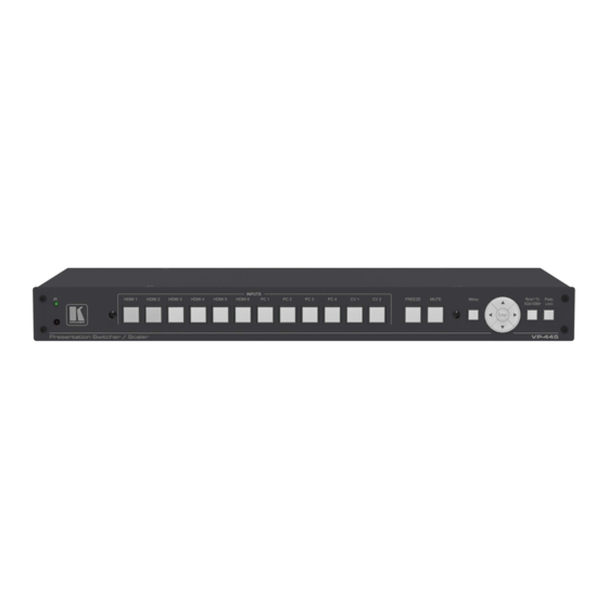
Page 13: Figure 1: Vp-445 Presentation Switcher/Scaler Front Panel
Figure 1: VP-445 Presentation Switcher/Scaler Front Panel Feature Function IR LED Lights when the unit accepts IR remote commands IR Receiver Receives signals from the remote control transmitter INPUT Selector HDMI Press to select the HDMI input (from 1 to 6) -
Page 14: Figure 2: Vp-445 Presentation Switcher/Scaler Rear Panel
Figure 2: VP-445 Presentation Switcher/Scaler Rear Panel Feature Function VIDEO INPUT HDMI Connects to an HDMI source (from 1 to 6) Connectors PC 15-pin HD Connects to a computer graphics source (from 1 to 4) CV RCA Connects to a composite video source (from 1 to 2) -
Page 15: Installing In A Rack
Installing in a Rack This section provides instructions for rack mounting the unit. VP-445 - Installing in a Rack... -
Page 16: Connecting The Vp-445
INPUT connector (from 1 to 6). Alternatively, you can connect the DVI connector on the DVD player to the HDMI connector on the VP-445 via a DVI-HDMI adapter. When using this adapter, you can connect the audio signal via the terminal block connector 2. -
Page 17: Figure 3: Connecting The Vp-445 Presentation Switcher / Scaler
9. If required, connect: A PC via RS-232, see Section 6 .3 The ETHERNET port, see Section 6 .4 Figure 3: Connecting the VP-445 Presentation Switcher / Scaler VP-445 - Connecting the VP-445... -
Page 18: Connecting The Balanced Stereo Audio Output
Audio Acceptor to the Balanced Output Stereo Audio Output Microphone Pinout The microphone 6mm jack pinout for a condenser microphone. Figure 6: Condenser Microphone Pinout The microphone 6mm jack pinout for a dynamic microphone. Figure 7: Dynamic Microphone Pinout VP-445 - Connecting the VP-445... -
Page 19: Controlling The Vp-445
FINETUNE menu (see .2.1). Using the OSD Menu The control buttons let you control the VP-445 via the OSD menu. Press the: MENU button to enter the menu The default timeout is set to 10 seconds ... -
Page 20: Main Menu
HDMI 4, HDMI 5, HDMI 6, PC1, PC2, CV1 and CV2 OUTPUT Set the output volume VOLUME: SETTINGS Set the BASS and TREBLE values Set the delay to OFF, 40ms, 110ms or 150ms (default is OFF) MUTE: Select the sound mute options: ON, OFF (default) VP-445 - Controlling the VP-445... -
Page 21: Figure 8: Talkover Mode
RELEASE TIME – to define the transition time for the audio level to return from its reduced level to its normal level after the Hold Time period MIC VOLUME Set the microphone volume for MIC1 and MIC2 Figure 8: Talkover Mode VP-445 - Controlling the VP-445... - Page 22 IP MODE is STATIC, provide the STATIC IP ADDRESS ( following IP ADDRESS Enter the IP address (192.168.1.39) SUBNET Enter the subnet (255.255.0.0) GATEWAY Enter the gateway (0.0.0.0) REMOTE PORT Enter the remote port (1~65535) MAC ADDRESS MAC address appears VP-445 - Controlling the VP-445...
-
Page 23: Connecting To The Vp-445 Via Rs-232
To connect to the VP-445 via RS-232, connect the RS-232 9-pin D-sub rear panel port on the VP-445 via a 9-wire straight cable (only connect pin 2 to pin 2, pin 3 to pin 3, and pin 5 to pin 5) to the RS-232 9-pin D-sub port on your PC. -
Page 24: Figure 9: Local Area Connection Properties Window
After connecting the VP-445 to the Ethernet port, configure your PC as follows: 1. Click Start > Control Panel > Network and Sharing Center. 2. Click Change Adapter Settings. 3. Highlight the network adapter you want to use to connect to the device and click Change settings of this connection. -
Page 25: Figure 10: Internet Protocol Version 4 Properties Window
5. Click Properties. The Internet Protocol Properties window relevant to your IT system appears as shown in Figure 10 Figure Figure 10: Internet Protocol Version 4 Properties Window Figure 11: Internet Protocol Version 6 Properties Window VP-445 - Controlling the VP-445... -
Page 26: Figure 12: Internet Protocol Properties Window
6.4.2 Connecting the Ethernet Port via a Network Hub or Switch You can connect the Ethernet port of the VP-445 to the Ethernet port on a network hub or using a straight-through cable with RJ-45 connectors. 6.4.3 Configuring the Ethernet Port You can set the Ethernet parameters via the embedded Web pages. -
Page 27: Using The Infrared Remote Control Transmitter
Using the Infrared Remote Control Transmitter You can control the VP-445 from the infrared remote control transmitter: Keys Function POWER Toggle the power save mode ON or OFF HDMI Select the HDMI input (from 1 to 6) Select the PC input (from 1 to... -
Page 28: Using The Embedded Web Pages
Using the Embedded Web Pages The VP-445 can be operated remotely using the embedded Web pages. The Web pages are accessed using a Web browser and an Ethernet connection. Before attempting to connect: Perform the procedures in Section ... -
Page 29: Input Select Page
The model name, FW version and IP address appear on the lower left side of the main page. The lower part of the screen lets you save the settings and upload a saved setting. Figure 14: Input Select Page VP-445 - Using the Embedded Web Pages... -
Page 30: Figure 15: Vp-445 Standby Mode
The input edit window lets you set the HDCP, change the name of the input as you want it to appear in the Web page (click to save the name), set the audio source and its volume. Click the exit icon ( ) to exit the window. VP-445 - Using the Embedded Web Pages... -
Page 31: Figure 17: Pc And Cv Input Edit Window
Figure 17 shows the PC and CV edit window. Click the exit icon ( ) to exit the window. Figure 17: PC and CV Input Edit Window VP-445 - Using the Embedded Web Pages... -
Page 32: Device Settings Page
18) lets you upgrade the firmware and set the Ethernet parameters. Figure 18: Device Settings Page Any change in the device settings requires confirmation, as illustrated in the example in Figure Figure 19: Device Settings Page – Static IP Confirmation. VP-445 - Using the Embedded Web Pages... -
Page 33: Figure 20: Device Settings Page - Uploading The New Firmware File
1. In the Firmware update field click the Choose File button to choose the firmware file. 2. Click the Upgrade button. The new firmware is uploaded: Figure 20: Device Settings Page – Uploading the New Firmware File VP-445 - Using the Embedded Web Pages... -
Page 34: Figure 21: Device Settings Page - Uploading Process
4. After restarting the system upload the Web page once again. 5. Verify that the new version appears on the lower left corner of the Web page: Figure 22: Device Settings Page – New Firmware Updated VP-445 - Using the Embedded Web Pages... -
Page 35: Output Settings Page
Output Settings page: Figure 23: Output Settings Page The output settings include the Resolution and Size of the image, the picture settings, and the Finetune items (which are enabled for VGA inputs). VP-445 - Using the Embedded Web Pages... -
Page 36: Hdcp Page
The HDCP page lets you set the HDCP on the output (follow input or follow output) and the HDCP status for each of the HDMI inputs. Figure 24 shows the HDCP page: Figure 24: HDCP Page VP-445 - Using the Embedded Web Pages... -
Page 37: Edid Page
EDID Page The EDID page lets you copy a selected resolution (Native Timing) or the default resolution (HDMI or VGA) to one or more selected inputs. Figure 25: EDID Page VP-445 - Using the Embedded Web Pages... -
Page 38: Figure 26: Edid Page - Copying A Selected Input Resolution
The EDID page displays the machine name, selected resolution, audio channels and deep color support. After clicking Copy, the EDID page shows the copy EDID results: Figure 27: EDID Page – Copying EDID Results VP-445 - Using the Embedded Web Pages... -
Page 39: Figure 28: Edid Page - Copying Edid From An Output
In the same way you can read the EDID from one of the outputs. To do so, select an output and click Copy: Figure 28: EDID Page – Copying EDID from an Output VP-445 - Using the Embedded Web Pages... -
Page 40: Audio Page
The Audio page also enables you to set mute follow freeze and lip sync as well as the audio source (automatic, analog or embedded for the HDMI inputs) and volume level for each input. Figure 29: Audio Page VP-445 - Using the Embedded Web Pages... -
Page 41: Advanced Page
(Off), set the auto switching to Off, Auto Scan or HDMI Last connected, set the input priority to PC or HDMI (once the auto scan is enabled), and set the Lock Mode, see Figure Figure 30: Advanced Page VP-445 - Using the Embedded Web Pages... -
Page 42: Rs-232 Page
RS-232 Page The RS-232 lets you set RS-232 to control VP-445 or to control an external device, for example a projector that is connected to the output or any other RS-232 controlled device. Figure 31: RS-232 Page To control an external device via VP-445: 1. -
Page 43: About Page
8. In the same way type as many commands as required. 7.10 About Page The VP-445 About page lets you view the Web page version and Kramer Electronics Ltd details. Figure 34: About Page VP-445 - Using the Embedded Web Pages... -
Page 44: Technical Specifications
10% to 90%, RHL non-condensing Dimensions: 19" x 7" x 1U (W, D, H) rack mountable Weight: 1.8kg (4lbs) approx. Included Accessories: Power cord, rack ears, IR remote control Specifications are subject to change without notice at www.kramerav.com VP-445 - Technical Specifications... -
Page 45: Default Communication Parameters
Example (Route the video HDMI3 input to the output ports): #ROUTE 1,1,3<cr> Input Resolutions Resolution/Refresh Rate Composite HDMI 480I/576I 480P/576P 720P@(50/60) 1080I@(50/60) 1080P@(50/60) 1080P@(24/25/30) VGA@(60/67/72/75/85) SVGA@(56/60/72/75) XGA@(60/70/75) SXGA@(60/75) 1280X960@60 1280x720@60 1920X1080@60 UXGA@60 ( 1600X1200 ) WXGA@60(1280x800) WXGA+@60(1440x900) WXGA@60(1366x768) SXGA+@60(1400x1050) 1600X900@60 RB WSXGA@60 RB(1680x1050 RB) VP-445 - Technical Specifications... -
Page 46: The Rs-232/Ethernet (Tcp) Communication Protocol
The VP-445 Presentation Switcher/Scaler can be operated using the Kramer Protocol 3000 serial commands. The command framing varies according to how you interface with the VP-445. In the following example, a basic video input switching command that routes a layer 1 video signal to HDBT out 1 from HDMI input 2 (ROUTE 1,1,2), is entered as follows: ... -
Page 47: Understanding Protocol 3000
You can enter commands directly using terminal communication software (e.g., Hercules) by connecting a PC to the serial or Ethernet port on the VP-445. To enter CR press the Enter key (LF is also sent but is ignored by the command parser). - Page 48 Spaces between parameters or command terms are ignored. Commands in the string do not execute until the closing character is entered. A separate response is sent for every command in the chain. VP-445 - The RS-232/Ethernet (TCP) Communication Protocol...
-
Page 49: Kramer Protocol 3000 Syntax
Kramer Protocol 3000 Syntax The Kramer Protocol 3000 syntax uses the following delimiters: CR = Carriage return (ASCII 13 = 0x0D) LF = Line feed (ASCII 10 = 0x0A) SP = Space (ASCII 32 = 0x20) Some commands have short name syntax in addition to long name syntax to enable faster typing. -
Page 50: Protocol 3000 Commands
Protocol handshaking Get: Response ~nn@ CR LF Notes Validates the Protocol 3000 connection and gets the machine number Step-in master products use this command to identify the availability of a device K-Config Example “#”,0x0D VP-445 - The RS-232/Ethernet (TCP) Communication Protocol... - Page 51 This command deletes all user data from the device. The deletion can take some time. Your device may require powering off and powering on for the changes to take effect. K-Config Example Reset the device to its factory default configuration: “#FACTORY”,0x0D VP-445 - The RS-232/Ethernet (TCP) Communication Protocol...
- Page 52 This command identifies equipment connected to Step-in master products and notifies of identity changes to the connected equipment. The Matrix saves this data in memory to answer REMOTE-INFO requests K-Config Example Get device model: “#MODEL?”,0x0D VP-445 - The RS-232/Ethernet (TCP) Communication Protocol...
- Page 53 To avoid locking the port due to a USB bug in Windows, disconnect USB connections immediately after running this command. If the port was locked, disconnect and reconnect the cable to reopen the port. K-Config Example Reset the device: “#RESET?”,0x0D VP-445 - The RS-232/Ethernet (TCP) Communication Protocol...
- Page 54 End User Public Description Syntax Set: #VERSION?CR Get: Get version number Response ~nn@VERSIONSPfirmware_versionCR LF Parameters firmware_version – Format: XX.XX.XXXX where the digits group are: major.minor.build version K-Config Example Get the firmware version number: “#VERSION?”,0x0D VP-445 - The RS-232/Ethernet (TCP) Communication Protocol...
- Page 55 – HDCP_ON [default] HDCP supported HDCP not supported – HDCP OFF HDCP support changes following detected sink – MIRROR OUTPUT K-Config Example Set HDCP mode on HDMI 1 output to Follow out “#HDCP-MOD 1,0,3”,0x0D VP-445 - The RS-232/Ethernet (TCP) Communication Protocol...
- Page 56 P2 – Scaler: 1 P3 – Video inputs: 0~11 (see Section 9 .4.1) Notes This command replaces all other routing commands. K-Config Example Select the HDMI 2 input to route to the outputs: “#ROUTE 1,1,2”,0x0D VP-445 - The RS-232/Ethernet (TCP) Communication Protocol...
- Page 57 End User Description Syntax #ROUTESPParamCR Set: Set menu navigation Get: Response nn@MENU_CMDSPParamCR LF Parameters Param – Menu=1, Enter=2, Up=4, Down=5, Right=6, Left=7) Notes This command emulates menu navigation K-Config Example Select menu: “#MENU-CMD 1”,0x0D VP-445 - The RS-232/Ethernet (TCP) Communication Protocol...
-
Page 58: Video Commands
“Get” command with is_native=ON returns native resolution VIC, with is_native=OFF returns current resolution To use “custom resolutions” (entries 100-105), define them using command DEF-RES K-Config Example Set video resolution on output to 1360x768 @60Hz “#VID-RES 1,1,0,204”,0x0D VP-445 - The RS-232/Ethernet (TCP) Communication Protocol... - Page 59 Get freeze on output status Response Set / Get: ~nn@VFRSPP1,P2CR LF Parameters P1 – 1 (Scaler) P2 – freeze status: 0 (Off), 1 (On) K-Config Example Set freeze video output to off: “#TREBLE 1,0”,0x0D VP-445 - The RS-232/Ethernet (TCP) Communication Protocol...
- Page 60 After execution, response is sent to all com ports if CMD-NAME was set any other external control device (button press, device menu and similar) or genlock status was changed Notes Sets the image properties of the selected scaler K-Config Example Set the image size to PanScan: “#IMAGE-PROP 1,3”,0x0D VP-445 - The RS-232/Ethernet (TCP) Communication Protocol...
- Page 61 (button press, device menu and similar) or genlock status was changed Notes Sets the PC Auto sync of the selected scaler K-Config Example Set the PC auto sync of the scaler to yes: “#SCLR-PCAUTO 1,1”,0x0D VP-445 - The RS-232/Ethernet (TCP) Communication Protocol...
- Page 62 Note that you can choose an input channel or the output, based on the selected P1. P3 – 0-100 (audio level) minus sign precedes negative values. ++ increase current value, -- decrease current value K-Config Example Set the HDMI 45 input AUD-LVL to 75: “#AUD-LVL 0,3,75”,0x0D VP-445 - The RS-232/Ethernet (TCP) Communication Protocol...
- Page 63 After execution, response is sent to all com ports if CMD-NAME was set any other external control device (button press, device menu and similar) or genlock status was changed Notes Mutes the selected audio output K-Config Example Mute the output: “#MUTE 1,1”,0x0D VP-445 - The RS-232/Ethernet (TCP) Communication Protocol...
- Page 64 Response ~nn@BASSSPchannel,bass_levelCR LF Parameters channel – 1 (scaler) bass_level – 0-30 (value) audio parameter in Kramer units, minus sign precedes negative values ++ increase current value -- decrease current value K-Config Example Set the bass level to 15: “#BASS 1,15”,0x0D 9.3.4.5...
- Page 65 (button press, device menu and similar) or genlock status was changed Notes Sets the Auto Sync features for the selected Scaler K-Config Example Set the auto sync off timer to slow: “#SCLR-AS 1,2”,0x0D VP-445 - The RS-232/Ethernet (TCP) Communication Protocol...
- Page 66 (button press, device menu and similar) or genlock status was changed Notes Sets the audio delay for the selected audio output K-Config Example Set the scaler audio delay to 40ms: “#SCLR-AUDIO-DELAY 1,1”,0x0D VP-445 - The RS-232/Ethernet (TCP) Communication Protocol...
- Page 67 Get audio talkover mode status Response ~nn@TLKSPchannel,talkover_modeCR LF Parameters channel – 1 (Scaler) talkover_mode – 0 (Off), 1 (Mixer), 2 (Talkover), 3 (Mic only) K-Config Example Set the scaler audio talkover mode to Mic only: “#TLK 1,3”,0x0D VP-445 - The RS-232/Ethernet (TCP) Communication Protocol...
- Page 68 Set: #MIC- SELECT?SPP1CR Get the microphone Get: Response ~nn@MIC- SELECT SPp1,p2CR LF Parameters P1 –scaler=1 P2 – Mic mode OFF=[], MIC1=1, MIC2=2, Both=[1, 2], [2, 1] K-Config Example Select microphone 1: “#MIC-SELECT 1,1”,0x0D VP-445 - The RS-232/Ethernet (TCP) Communication Protocol...
-
Page 69: Communication Commands
Communication Description Syntax Set: #NET-MAC?CR Get: Get MAC address Response ~nn@NET-MACSPmac_addressCR LF Parameters mac_address – Unique MAC address. Format: XX-XX-XX-XX-XX-XX where X is hex digit. K-Config Example Get the MAC address: “#NET-MAC? XX-XX-XX-XX-XX-XX”,0x0D VP-445 - The RS-232/Ethernet (TCP) Communication Protocol... - Page 70 A network gateway connects the device via another network and maybe over the Internet. Be careful of security problems. For proper settings consult your network administrator K-Config Example Set the gateway IP address to 192.168.0.1: “#NET-GATE 192.168.000.001”,0x0D VP-445 - The RS-232/Ethernet (TCP) Communication Protocol...
- Page 71 “NAME”. You can also get an assigned IP by direct connection to USB or RS-232 protocol port if available. For proper settings consult your network administrator. K-Config Example Set the DHCP mode to static: “#NET-DHCP 0”,0x0D VP-445 - The RS-232/Ethernet (TCP) Communication Protocol...
- Page 72 Set Ethernet port protocol # ETH-PORT?SPporttypeCR Get: Get Ethernet port protocol Response Set: ~nn@ ETH-PORT SPporttype,ethportCR LF Parameters porttype – TCP=0 ethport – 1 to 65535 K-Config Example Set TCP to 2: “#ETH-PORT 0,2”,0x0D VP-445 - The RS-232/Ethernet (TCP) Communication Protocol...
-
Page 73: Kramer Protocol 3000 -Command Keys
720p @60Hz 1360x768 @60Hz 1080i @60Hz 1280x720 @60Hz 1080p @60Hz 1280x800 @60Hz 576p @50Hz 1280x1024 @60Hz 720p @50Hz 1440x900 @60Hz 1080i @50Hz 1400x1050 @60Hz 1080p @50Hz NATIVE OUT1 1680x1050 @60Hz NATIVE OUT2 1600x1200 @60Hz VP-445 - The RS-232/Ethernet (TCP) Communication Protocol... -
Page 75: Safety Warning
SAFETY WARNING Disconnect the unit from the power supply before opening and servicing For the latest information on our products and a list of Kramer distributors, visit our Web site where updates to this user manual may be found. We welcome your questions, comments, and feedback.
Need help?
Do you have a question about the VP-445 and is the answer not in the manual?
Questions and answers