
Subscribe to Our Youtube Channel
Related Manuals for Kramer VP-444


Summary of Contents for Kramer VP-444
-
Page 1: User Manual
K R A ME R E LE CT R O N IC S L TD . USER MANUAL MODEL: VP-444 Presentation Switcher/Scaler P/N: 2900-300305 Rev 1... -
Page 4: Table Of Contents
Microphone Pinout Controlling the VP-444 Controlling via the Front Panel Buttons Using the OSD Menu Connecting to the VP-444 via RS-232 Operating via Ethernet Controlling via the Infrared Remote Control Transmitter Using the Embedded Web Pages Browsing the VP-444 Web Pages... - Page 5 Figure 1: VP-444 Presentation Switcher/Scaler Front Panel Figure 2: VP-444 Presentation Switcher/Scaler Rear Panel Figure 3: Connecting the VP-444 Presentation Switcher / Scaler Figure 4: Connecting the Balanced Stereo Audio Output Figure 5: Connecting an Unbalanced Stereo Audio Acceptor to the Balanced Output...
-
Page 6: Introduction
1 Introduction Welcome to Kramer Electronics! Since 1981, Kramer Electronics has been providing a world of unique, creative, and affordable solutions to the vast range of problems that confront video, audio, presentation, and broadcasting professionals on a daily basis. In recent years, we have redesigned and upgraded most of our... -
Page 7: Getting Started
Avoid interference from neighboring electrical appliances that may adversely influence signal quality Position your Kramer VP-444 away from moisture, excessive sunlight and dust This equipment is to be used only inside a building. It may only be connected to other equipment that is installed inside a building. -
Page 8: Safety Instructions
Kramer Electronics has made arrangements with the European Advanced Recycling Network (EARN) and will cover any costs of treatment, recycling and recovery of waste Kramer Electronics branded equipment on arrival at the EARN facility. For details of Kramer’s recycling arrangements in your particular country go to our recycling pages at http://www.kramerelectronics.com/support/recycling/. -
Page 9: Overview
3 Overview The VP-444 is a high−performance presentation scaler/switcher for HDMI and computer graphics signals. The unit scales the video, embeds the audio, and outputs the signal to two HDMI (with embedded audio) outputs (with S/PDIF and balanced stereo audio) simultaneously. -
Page 10: Defining The Vp-444 Presentation Switcher/Scaler
Via the Ethernet with built-in Web pages The VP-444 is housed in a 19” 1U rack mountable enclosure, with rack “ears” included, and is fed from a 100-240 VAC universal switching power supply. Defining the VP-444 Presentation Switcher/Scaler This section defines the VP-444. -
Page 11: Figure 1: Vp-444 Presentation Switcher/Scaler Front Panel
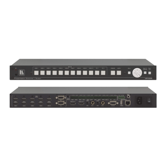
Figure 1: VP-444 Presentation Switcher/Scaler Front Panel Feature Function IR LED Lights when the unit accepts IR remote commands IR Receiver Receives signals from the remote control transmitter INPUT Selector HDMI Press to select the HDMI input (from 1 to 10) -
Page 12: Figure 2: Vp-444 Presentation Switcher/Scaler Rear Panel
Figure 2: VP-444 Presentation Switcher/Scaler Rear Panel Feature Function VIDEO INPUT HDMI Connect to the HDMI source (from 1 to 10) Connectors PC 15-pin HD Connect to the computer graphics source (from 1 to 2) AUDIO INPUT Unbalanced HDMI Connect to the analog audio HDMI source (from 1 to 10) -
Page 13: Installing In A Rack
4 Installing in a Rack This section provides instructions for rack mounting the unit. VP-444 - Installing in a Rack... -
Page 14: Connecting The Vp-444
VIDEO INPUT connector (from 1 to 10). Alternatively, you can connect the DVI connector on the DVD player to the HDMI connector on the VP-444 via a DVI-HDMI adapter. When using this adapter, you can connect the audio signal via the terminal block connector 2. -
Page 15: Figure 3: Connecting The Vp-444 Presentation Switcher / Scaler
Figure 3: Connecting the VP-444 Presentation Switcher / Scaler VP-444 - Connecting the VP-444... -
Page 16: Connecting The Balanced Stereo Audio Output
Audio Acceptor to the Balanced Output Microphone Pinout The microphone 6mm jack pinout for a condenser microphone. Figure 6: Condenser Microphone Pinout The microphone 6mm jack pinout for a Dynamic microphone. Figure 7: Dynamic Microphone Pinout VP-444 - Connecting the VP-444... -
Page 17: Controlling The Vp-444
FINETUNE menu (see Section 6.2.1). Using the OSD Menu The control buttons let you control the VP-444 via the OSD menu. Press the: MENU button to enter the menu The default timeout is set to 10 seconds ... -
Page 18: The Main Menu
AUDIO: AUTOMATIC: the embedded audio on the HDMI input is selected for an HDMI signal, or the analog audio input is selected if the input is not HDMI (for example, for a DVI input signal) VP-444 - Controlling the VP-444... - Page 19 CONTROL PORT Enter the control port MAC ADDRESS MAC address FACTORY RESET Select NO or YES INFORMATION Displays the INPUT RESOLUTION, the OUTPUT RESOLUTION, INPUT HDCP (HDCP/NONE), OUTPUT 1/2 HDCP (HDCP/NONE) VERSION and the IP ADDRESS VP-444 - Controlling the VP-444...
-
Page 20: Connecting To The Vp-444 Via Rs-232
6.4.1 Connecting the Ethernet Port Directly to a PC You can connect the Ethernet port of the VP-444 directly to the Ethernet port on your PC using a crossover cable with RJ-45 connectors. This type of connection is recommended for identifying the VP-444 with the factory configured default IP address. -
Page 21: Figure 8: Local Area Connection Properties Window
4. Highlight either Internet Protocol Version 6 (TCP/IPv6) or Internet Protocol Version 4 (TCP/IPv4) depending on the requirements of your IT system. 5. Click Properties. The Internet Protocol Properties window relevant to your IT system appears as shown in Figure 9 Figure VP-444 - Controlling the VP-444... -
Page 22: Figure 9: Internet Protocol Version 4 Properties Window
Figure 9: Internet Protocol Version 4 Properties Window Figure 10: Internet Protocol Version 6 Properties Window VP-444 - Controlling the VP-444... -
Page 23: Figure 11: Internet Protocol Properties Window
8. Click Close. 6.4.2 Connecting the Ethernet Port via a Network Hub or Switch You can connect the Ethernet port of the VP-444 to the Ethernet port on a network hub or using a straight-through cable with RJ-45 connectors. 6.4.3 Configuring the Ethernet Port You can set the Ethernet parameters via the embedded Web pages. -
Page 24: Controlling Via The Infrared Remote Control Transmitter
Controlling via the Infrared Remote Control Transmitter You can control the VP-444 from the infrared remote control transmitter: Keys Function POWER Toggle the power save mode ON or OFF HDMI Select the HDMI input (from 1 to 10) Select the PC 1 input... -
Page 25: Using The Embedded Web Pages
7 Using the Embedded Web Pages The VP-444 can be operated remotely using the embedded Web pages. The Web pages are accessed using a Web browser and an Ethernet connection. Before attempting to connect: Perform the procedures in Section 6.4. -
Page 26: Browsing The Vp-444 Web Pages
The HDCP page (see Section 7.5) The EDID page (see Section 7.6) The Audio page (see Section 7.7) The Advanced page (see Section 7.8) The About page (see Section 7.9) VP-444 - Using the Embedded Web Pages... -
Page 27: The Input Select Page
) lets you mute ( ) or unmute the audio output level. Use the freeze icon ( ) to freeze a selected input. Use the edit icon ( ) to edit the input. VP-444 - Using the Embedded Web Pages... -
Page 28: Figure 14: Edit Input Buttons
Web page and save it, and also set the audio source and its volume. When selecting a PC input you can change the inputs’ name and set the input volume. Upon completion, save the changes and click the exit icon ( VP-444 - Using the Embedded Web Pages... -
Page 29: The Device Settings Page
15) lets you upgrade the firmware and set the Ethernet parameters. Figure 15: The Device Settings Page Any change in the device settings requires confirmation, as illustrated in the example Figure Figure 16: The Device Settings Page – Static IP Confirmation. VP-444 - Using the Embedded Web Pages... -
Page 30: Figure 17: The Device Settings Page - Uploading The New Firmware File
3. Once the file is uploaded follow the instructions on the Web page: The new firmware is uploaded: Figure 18: The Device Settings Page – Uploading the New Firmware File 4. After restarting the system you need to upload the Web page once again. VP-444 - Using the Embedded Web Pages... -
Page 31: The Output Settings Page
Figure 20 shows the Output Settings page: Figure 20: The Output Settings Page The output settings, include the Resolution and Size, the Finetune items (which are enabled for VGA inputs), and the picture settings. VP-444 - Using the Embedded Web Pages... -
Page 32: The Hdcp Page
The HDCP page lets you set the HDCP on the output (follow input or follow output) and the HDCP status for each of the HDMI inputs. Figure 21 shows the HDCP page: Figure 21: The HDCP Page VP-444 - Using the Embedded Web Pages... -
Page 33: The Edid Page
(HDMI or VGA) to one or more selected inputs. Figure 22: The EDID Page Figure 23 shows how to select a resolution from the list and select one or more inputs. To copy, click the Copy button: VP-444 - Using the Embedded Web Pages... -
Page 34: Figure 23: The Edid Page - Copying The Default
Figure 23: The EDID Page – Copying the Default The EDID page displays the machine name, selected resolution, the audio channels and deep color support. After clicking the Copy button, the EDID page shows the copy EDID results: VP-444 - Using the Embedded Web Pages... -
Page 35: Figure 24: The Edid Page -The Copy Edid Results
Figure 24: The EDID Page –The Copy EDID Results Click Close to complete the EDID procedure. VP-444 - Using the Embedded Web Pages... -
Page 36: The Audio Settings Page
The Advanced setting page lets you set the auto sync off speed (either slow or fast) or disable it (Off), set the auto switching to Off, Auto Scan or Last Connected and set the input priority to PC or HDMI (once the auto scan is enabled), see Figure VP-444 - Using the Embedded Web Pages... -
Page 37: The About Page
Figure 26: The Advanced Page The About Page The VP-444 About page lets you view the Web page version and Kramer Electronics Ltd details. Figure 27: The About Page VP-444 - Using the Embedded Web Pages... -
Page 38: Technical Specifications
10% to 90%, RHL non-condensing DIMENSIONS: 19" x 7" x 1U (W, D, H) rack mountable WEIGHT: 2.7kg (6lbs) approx. INCLUDED ACCESSORIES: Power cord, rack ears, IR remote control Specifications are subject to change without notice at http://www.kramerelectronics.com VP-444 - Technical Specifications... -
Page 39: Default Communication Parameters
640x480 (60/72/75/85Hz) 800x600 (56/60/72/75/85Hz) 1024x768 (60/70/75/85Hz) 1280x720 60Hz 1280x800 60Hz 1280x1024 (60/75/85Hz) 1366x768 60Hz 1400x1050 60Hz 1440x900 60Hz 1600x1200 60Hz 1600x900 RB 60Hz 1680x1050 RB 60Hz 1920x1080 60Hz 1920x1200 RB 60Hz 480I/576I 480P/576P 720P(50/60Hz) 1080I(50/60Hz) 1080P(24/25/30Hz) 1080P(50/60Hz) VP-444 - Technical Specifications... -
Page 40: The Vp-444 Rs-232 Communication Protocol
The VP-444 RS-232 Communication Protocol The VP-444 can be operated using serial commands from a PC, remote controller, or touch screen. The unit communicates using the default Kramer Protocol 3000. Kramer Protocol 3000 syntax (see Section 9.1) Kramer Protocol 3000 commands (see Section 9.2) - Page 41 CRLF – For machine messages; carriage return (ASCII 13) + line-feed (ASCII 10) Command chain separator character When a message string contains more than one command, a pipe ( '|' ) character separates each command. Spaces between parameters or command terms are ignored. VP-444 - The VP-444 RS-232 Communication Protocol...
- Page 42 You can directly enter all commands using a terminal with ASCII communications software, such as HyperTerminal, Hercules, etc. Connect the terminal to the serial or Ethernet port on the Kramer device. To enter CR press the Enter key. ( LF is also sent but is ignored by command parser).
-
Page 43: Kramer Protocol 3000 - Command List
#HDCP-MOD #HDCP-MOD? #VID-RES Set input/output resolution #VID-RES? Get input/output resolution #VFRZ #VFRZ? #AUD-LVL Set audio level #AUD-LVL? Get audio level #MIX #MIX? #MUTE #MUTE? #SCLR-AS #SCLR-AS? #IMAGE-PROP #IMAGE-PROP? #SCLR-PCAUTO #SCLR-AUDIO-DELAY #SCLR-AUDIO-DELAY? #MIC-GAIN #MIC-GAIN? VP-444 - The VP-444 RS-232 Communication Protocol... -
Page 44: Kramer Protocol 3000 - Detailed Commands
720p @60Hz 1360x768 @60Hz 1080i @60Hz 1280x720 @60Hz 1080p @60Hz 1280x800 @60Hz 576p @50Hz 1280x1024 @60Hz 720p @50Hz 1440x900 @60Hz 1080i @50Hz 1400x1050 @60Hz 1080p @50Hz NATIVE OUT1 1680x1050 @60Hz NATIVE OUT2 1600x1200 @60Hz VP-444 - The VP-444 RS-232 Communication Protocol... - Page 45 End User Get: Description Syntax Set: Reset device to factory defaults configuration #FACTORY␍ Get : Response ~nn@BUILD-DATE␠date␠time␍␊ Notes This command deletes all user data from the device. The deletion can take some time. VP-444 - The VP-444 RS-232 Communication Protocol...
- Page 46 Command Command Name Permission Transparency Set: Get: VERSION? End User Description Syntax Set: Get : Get version number #VERSION?␍ Response ~nn@VERSION␠firmware_version␍␊ Parameters firmware_version – Format: XX.XX.XXXX where the digits group are: major.minor.build version VP-444 - The VP-444 RS-232 Communication Protocol...
- Page 47 Get: ~nn@ NET-GATE ␠ ip_address ␍␊ Parameters P1 (valid IP address)=xxx.xxx.xxx.xxx Notes A network gateway connects the device via another network and maybe over the Internet. Be careful of security problems. For proper settings consult your network administrator VP-444 - The VP-444 RS-232 Communication Protocol...
- Page 48 To connect with a randomly assigned IP by DHCP, specify the device DNS name (if available) using the command “NAME”. You can also get an assigned IP by direct connection to USB or RS-232 protocol port if available. For proper settings consult your network administrator. VP-444 - The VP-444 RS-232 Communication Protocol...
- Page 49 Response is sent after every change in output HPD status ON to OFF Response is sent after every change in output HPD status OFF to ON and ALL parameters (new EDID, etc.) are stable and valid VP-444 - The VP-444 RS-232 Communication Protocol...
- Page 50 (button press, device menu and similar) or genlock status changed Notes Set HDCP working mode on device input : – HDCP_ON [default] HDCP supported HDCP not supported – HDCP OFF HDCP support changes following detected sink – MIRROR OUTPUT VP-444 - The VP-444 RS-232 Communication Protocol...
- Page 51 Get : Get freeze on output status # VFRZ? ␠ P1 ␍ Response Set / Get : ~ nn@ VFRZ ␠ P1,P2 ␍␊ Parameters P1 (Scaler number) – 1=Scaler P2 (Off/On) – 0=Off; 1=On VP-444 - The VP-444 RS-232 Communication Protocol...
- Page 52 #MIX␠ P1,P2 ␍ Set audio MIX Get : #MIX? ␠ P1 ␍ Get audio MIX Response ~nn@MIX␠ channel, mix_mode ␍␊ Parameters P1 (Output number) – 1=Scaler P2 (Off/On)– 0=Off; 1=Mic 1; 2=Mic 2; 3=both VP-444 - The VP-444 RS-232 Communication Protocol...
- Page 53 After execution, response is sent to all com ports if CMD-NAME was set any other external control device (button press, device menu and similar) or genlock status was changed Notes Sets the Auto Sync features for the selected Scaler VP-444 - The VP-444 RS-232 Communication Protocol...
- Page 54 After execution, response is sent to all com ports if CMD-NAME was set any other external control device (button press, device menu and similar) or genlock status was changed Notes Sets the PC Auto sync of the selected scaler VP-444 - The VP-444 RS-232 Communication Protocol...
- Page 55 After execution, response is sent to all com ports if CMD-NAME was set any other external control device (button press, device menu and similar) or genlock status was changed Notes Sets the Microphone input audio gain VP-444 - The VP-444 RS-232 Communication Protocol...
- Page 57 For the latest information on our products and a list of Kramer distributors, visit our Web site where updates to this user manual may be found. We welcome your questions, comments, and feedback. Web site: www.kramerelectronics.com E-mail: info@kramerel.com SAFETY WARNING...
Need help?
Do you have a question about the VP-444 and is the answer not in the manual?
Questions and answers