Advertisement
Quick Links
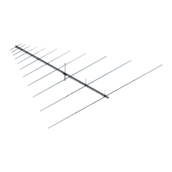
SPECIFICATIONS:
Model ......................................... 6-30LP11
Frequency Range ....................... 6 To 30 MHz
*Gain .......................................... 5 To 6.2 dBi
Front to back .............................. 10 To 20 dB Typical
Feed Impedance. ....................... 50 Ohms Unbalanced
Maximum VSWR ........................ 1.8:1 Max, Under 1.5
I
FEATURES:
The 6-30lp11 log periodic is a modern design both mechanically and electrically. Top quality materials combined
with many CNC machined parts will keep it trouble free for years or operation. Performance is excellent and specific path
gain can be as much as 12 dB with ground gain factored in. The 6-30LP11 is available individually or in a turnkey system,
complete with support tower, rotation mechanism and controller. Many options exist within the turnkey system such as
height and type of tower, rotator mechanism, and controller type. As pictured above and originally supplied to NASA at
Edwards air Force Base in Edwards California, the tower was a special, massive, motorized, self supporting 72 foot tower
supplied by US tower Corp to M
band antennas.
M2 Antenna Systems, Inc. 4402 N. Selland Ave. Fresno, CA 93722
M2 Antenna Systems, Inc.
Model No: 6-30LP11
*Subtract 2.14 from dBi for dBd
2
specifications. The 6-30LP11 is the latest Log to join the M
Tel: (559) 432-8873 Fax: (559) 432-3059 Web: www.m2inc.com
©2015 M2 Antenna Systems Incoporated
Input Connector .......................... "N" Female
Power Handling .......................... 3 Kw, Higher Optional
Boom Length / Type ................... 80' / Steel Tower
Turning Radius: .......................... 65'
Wind area / Survival ................... 125 MPH
Weight / Ship Wt. ........................ 1,228 Lbs.
2
Family of high quality broad
06/09/15
Rev.01
Advertisement

Related Manuals for M2 Antenna Systems 6-30LP11


Summary of Contents for M2 Antenna Systems 6-30LP11
-
Page 1: Specifications
CNC machined parts will keep it trouble free for years or operation. Performance is excellent and specific path gain can be as much as 12 dB with ground gain factored in. The 6-30LP11 is available individually or in a turnkey system, complete with support tower, rotation mechanism and controller. - Page 2 6-30LP11 ASSEMBLY MANUAL BEFORE YOU BEGIN: Look over the ELEMENT ASSEMBLY sheets to get familiar with the various parts of the log periodic. These written instructions attempt to give some order and efficiency to the overall assembly and make you aware of critical areas. TWO CUPS OF ZINC PASTE HAS BEEN PROVIDED AND SHOULD BE USED AT EACH JOINT WHERE MACHINED PARTS JOIN ALUMINUM RODS OR TUBES AND GENERALLY AT EACH ELECTRICAL CONNECTION POINT.
- Page 3 6-30LP11 ASSEMBLY MANUAL 4. Element #6 is similar as well but has internal sleeves to strengthen the element. It has a 1-1/4” diameter element butt and needs a 1” FIBERGLASS ROD, POLY DISCS with 1” hole and PHASE LINE CLAMPS with 1-1/4” hole.
- Page 4 6-30LP11 ASSEMBLY MANUAL 7. Assemble the three inner section of ELEMENT #3. NOTE that the PHASE LINE CLAMPS and PHASING LINE CLAMP CAPS have been replaced with pairs of 3/8” CLAMP BLOCKS held in place with the same bolt that keeps the element on the 2” FIBERGLASS ROD. These 3/8”...
- Page 5 6-30LP11 BOOM TOWERASSEMBLY 1. Use 1/2-13 X 2” (grade 5) galvanized bolts, 1/2-13 galvanized nut & 1/2-13 galvanized pal nut for all tower boom section joints. 2. Shims (as shown) are supplied with tower sections to help align. Use as needed.
- Page 6 6-30LP11 ELEMENT ASSEMBLY #4-11...
- Page 7 6-30LP11 ELEMENT ASSEMBLY #3...
- Page 8 6-30LP11 ELEMENT ASSEMBLY #2...
- Page 9 6-30LP11 ELEMENT ASSEMBLY #1...
- Page 10 6-30LP11 ELEMENT INSTALLATION 1. Begin by installing element #11, the smallest element. Locate the bag of twenty (20) HD CRA- DLES with 7/8” radius to fit the 7/8” fiberglass rods. These cradles have clearance holes for 5/16” diameter bolts. Drop four (4) 5/16-24 x 4” bolts down through the element #11 mounting plate.
- Page 11 6-30LP11 OVERHEAD SUPPORT 1. INSTALLING THE ELEMENT VERTICAL SUPPORT BRACKETS AND ELEMENT VERTICAL SUPPORT MASTS ON ELEMENT #2 AND #1. Set the bracket over element #2 as shown. Mount the VERTICAL ELEMENT SUPPORT MAST using 1-1/2” U-bolts and rotate the mast so the holes in the top flag are over the element.
- Page 12 6-30LP11 BALUN & PHASE LINE 1. Mount the 4:1 BALUN MOUNTING PLATE assembly to the TOWER BOOM just behind element #11 as shown above. Route the balun leads to the 1/4-20 x 1-1/2 bolts through the element butts and tighten securely.
- Page 13 6-30LP11 BALUN & PHASE LINE 5. Continue adding these 3/16” rod phasing line assemblies until you reach and finish Element #4. Tighten the 3/16” PHASE LINE CLAMPS on element #4. Note: 3/8” tube phasing lines are used between element #4 through element #1.
- Page 14 6-30LP11 BOOM OVERHEAD SUPPORT 1. The physical balance point of the antenna is about 30” to the rear of the center TOWER BOOM joint as shown below. The DRIVE MAST BRACKET (sold separate), will mount just below the MAST PLATE “L” & “R” that bolt on to the OVERHEAD MAST BRACKET (shown below).
- Page 15 6-30LP11 PARTS & HARDWARE ELEMENT #1 12-18-08 DESCRIPTION ELE 1 SEC 1, 3” X .125 X 120” SOE, 6061-T6 ELE 1 SEC 2, 2-1/2 X .125 X 116”, SOE 6061-T6 ELE 1 SEC 3, 2” X .125 X 110” SOE, 6061-T6 ELE 1 SEC 4, 1-1/2”...
- Page 16 6-30LP11 PARTS & HARDWARE ELEMENT #2 12-18-08 DESCRIPTION ELE 2 SEC 1, 3” X .125 X 74” SOE, 6061-T6 ELE 2 SEC 2, 2-1/2 X .125 X 79”, SOE 6061-T6 ELE 2 SEC 3, 2” X .125 X 64” SOE 6061-T6 ELE 2 SEC 4, 1-1/2 X .058 X 63”...
- Page 17 6-30LP11 PARTS & HARDWARE ELEMENT #3 12-18-08 DESCRIPTION ELE 3 SEC 1, 3” X .125 X 36” SOE, 6061-T6 ELE 3 SEC 2, 2-1/2 X .125 X 41”, SOE 6061-T6 ELE 3 SEC 3, 2” X .125 X 49” SOE 6061-T6 ELE 3 SEC 4, 1-1/2 X .058 X 63”...
- Page 18 6-30LP11 PARTS & HARDWARE 6-30LP11 BOOM 12-18-08 DESCRIPTION BOOM TOWER SECTION #1 BOOM TOWER SECTION #2 BOOM TOWER SECTION #3 BOOM TOWER SECTION #4 DRIVE MAST WELDMENT, ZINC 1 OPTIONAL MAST PLATE, WELDMENT, ZINC MAST PLATE “L” MAST PLATE “R”...
- Page 19 6-30LP11 PARTS & HARDWARE PHASING LINE SYSTEM & FEED 12-18-08 DESCRIPTION 3/8” X 204” TUBE, BENT, 6063-T832 3/8” X 172” TUBE, BENT, 6063-T832 3/8” X 137” TUBE, BENT, 6063-T832 3/16” X ROD, BENT, 6061-T6 3/16” X ROD, BENT, 6061-T6 3/16” X ROD, BENT, 6061-T6 3/16”...
- Page 20 6-30LP11 PARTS & HARDWARE ELEMENT #4 TO #11 12-18-08 DESCRIPTION SLEEVE, 1-5/8” X .058 X 56” ELE 4 SEC 1A, 1-1/2” X .058 X 60” SOE ( 1/4 HOLE, TO FIT SELF) ELE 4 SEC 2B, 1-1/2” X .058 X 60” SOE (TO EXCEPT 1 1/4) ELE 5 SEC 1, 1-1/2”...
- Page 21 6-30LP11 PARTS & HARDWARE ELEMENT #4 TO #11 CONTINUED 12-18-08 HARDWARE BOLT, 5/16-24 X 4 1/2 ” GRADE 5 BOLT, 5/16-24 X 4” GRADE 5 NUT, 5/15-24 LOCKING,ZINC BOLT, 1/4-20 2-1/2” SS BOLT, 1/4-20 X 2” SS BOLT, 1/4-20 X 1-1/2” SS SCREW, 1/4-20 X 1”...
- Page 22 6-30LP11 PARTS IDENTIFICATION...
- Page 23 6-30LP11 SPARE PARTS 1-15-09 DESCRIPTION BOLT, 3/8-16 X 4”, SS ............2 BOLT, 3/8-16 X 3-1/2”, SS ........... 2 NUT, LOCKING, 3/8-16, SS ..........6 BOLT, 3/8-24 X 5”, GRADE 5 ..........12 NUT, LOCKING, 3/8-24, ZINC ..........10 BOLT, 1/4-20 X 3-1/4”, SS ........... 4 BOLT, 1/4-20 X 2-3/4”, SS ...........
Need help?
Do you have a question about the 6-30LP11 and is the answer not in the manual?
Questions and answers