Table of Contents
Advertisement
Quick Links
Advertisement
Table of Contents

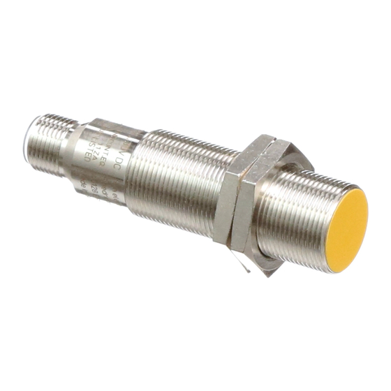
Summary of Contents for IFM Efector 100 GG712S
- Page 1 Original operating instructions Fail-safe inductive sensor GG712S ...
-
Page 2: Table Of Contents
Contents 1 Preliminary note ���������������������������������������������������������������������������������������������������3 1�1 Explanation of symbols ����������������������������������������������������������������������������������3 2 Safety instructions �����������������������������������������������������������������������������������������������4 2�1 Safety-related requirements regarding the application ����������������������������������4 3 Items supplied������������������������������������������������������������������������������������������������������5 4 Functions and features ����������������������������������������������������������������������������������������5 5 Functions �������������������������������������������������������������������������������������������������������������6 5�1 Enable zone ���������������������������������������������������������������������������������������������������6 6 Installation������������������������������������������������������������������������������������������������������������7 7 Electrical connection ��������������������������������������������������������������������������������������������8 7�1 Operation as 4-wire unit ��������������������������������������������������������������������������������8 7�2 Operation as 3-wire unit ��������������������������������������������������������������������������������8 8 Operation �������������������������������������������������������������������������������������������������������������9... -
Page 3: Preliminary Note
1 Preliminary note The instructions are part of the unit� They are intended for authorised persons according to the EMC and Low Voltage Directive and safety regulations� The instructions contain information about the correct handling of the product� Read the instructions before use to familiarise yourself with operating conditions, installation and operation�... -
Page 4: Safety Instructions
2 Safety instructions • Follow the operating instructions� • Improper use may result in malfunctions of the unit� This can lead to personal injury and/or damage to property during operation of the machine� For this reason note all remarks on installation and handling given in these instructions� Also adhere to the safety instructions for the operation of the whole installation�... -
Page 5: Items Supplied
1 fail-safe sensor GG712S with 2 mounting nuts M18, 1 operating instructions GG712S, ident no� 704229� If one of the above-mentioned components is missing or damaged, please contact one of the ifm branch offices� 4 Functions and features The fail-safe inductive sensor GG712S detects metal without contact�... -
Page 6: Functions
5 Functions LEDs fail-safe sensor close zone enable zone safe switch-off distance s damping element Yellow signal LED: switching status Green power LED: operating voltage 5.1 Enable zone The outputs (OSSD) are only enabled when a damping target is present in the enable zone�... -
Page 7: Installation
Depending on the characteristics of the damping element there may be no close zone� 6 Installation The unit can be flush mounted according to IEC 60947-5-2, type I1A18SP2� ► Ensure the unit cannot work loose� Maximum tightening torque: 30 Nm ► Adhere to the installation conditions in accordance with the figures 1 to 3: 56 mm 21 mm 18 mm... -
Page 8: Electrical Connection
7 Electrical connection ► Disconnect power� Also disconnect any independently supplied relay load circuits� ► Supply voltage: connect L+ to pin 1 and L– to pin 3 of the connector� The nominal voltage is 24 V DC� This voltage may vary between 19�2 V and 30 V incl�... -
Page 9: Operation
In case of operation as 3-wire unit only A2 must be used as output (OSSD). Otherwise the safety function of the sensor will be impaired or prevented. ► Connect output A1 to supply voltage� ► Make absolutely sure to exclude cross faults and short circuits between the supply voltage and output A2 by means of appropriate installation! The indicated values regarding the safety function (→ 10 Technical data) remain unchanged�... -
Page 10: 8�2 Response Times
8.2 Response times Response time on safety request ≤ 1 ms (removal from the enable zone) Response time when approaching the enable zone ≤ 1 ms (enable time) Risk time / response time for safety-related faults ≤ 20 ms Simultaneity of switching on and off of the outputs in case of a safety ≤... -
Page 11: Scale Drawing
9 Scale drawing 70,5 LED 2 x 180° 10 Technical data GG712S GIGA4005-2PS/SIL2/US Fail-safe inductive sensor Metal thread M18 x 1 M12 connector Enable zone: ≤ 1 ��� ≥ 5 mm Conforms to the requirements of: SIL 2 to IEC 61508, SILcl 2 to IEC 62061, PL d to EN ISO 13849-1 flush mountable Operating voltage 24 V DC (19�2���30 V) - Page 12 Response time response time on safety request (removal from the enable zone) ≤ 1 ms response time when approaching the enable zone (enable time): ≤ 1 ms Risk time (response time for safety-related ≤ 20 ms faults) Power-on delay time Safe switch-off distance s >...
- Page 13 Wiring (BN) +24 V (WH) (BU) (BK) Evaluation unit or PLC Core colours: BK: black BN: brown BU: blue WH: white Remarks: Unless stated otherwise, all data refer to the 18 x 18 x 1 mm reference target plate to IEC 60947-5-2 (FE360 = mild steel) over the whole temperature range�...
-
Page 14: Troubleshooting
11 Troubleshooting → 8�3 LED display Problem Possible cause Troubleshooting No LED display No voltage supply Apply voltage Power LED flashes and • Undervoltage Correct the voltage sensor does not switch • Overvoltage (→ 10 Technical data) Sensor does not switch, Sensor was brought into the •... -
Page 15: Approvals/Standards
13 Approvals/standards The following standards and directives have been applied: • 2006/42/EC European machinery directive • 2004/108/EC EMC directive • EN ISO 13849-1 PL d (2006) Safety of machinery - Safety-related parts of control systems • IEC 60947-5-2 (2008) low voltage switchgear and controlgear: control circuit devices and switching elements - proximity switches •...


Need help?
Do you have a question about the Efector 100 GG712S and is the answer not in the manual?
Questions and answers