Table of Contents
Advertisement
Quick Links
Advertisement
Table of Contents

Related Manuals for IFM efector 160 LR3000


Summary of Contents for IFM efector 160 LR3000
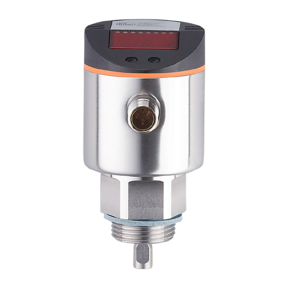
- Page 1 Operating instructions Electronic level sensor LR3000...
-
Page 2: Table Of Contents
Contents 1 Preliminary note ���������������������������������������������������������������������������������������������������4 1�1 Symbols used ������������������������������������������������������������������������������������������������4 2 Safety instructions �����������������������������������������������������������������������������������������������4 3 Items supplied������������������������������������������������������������������������������������������������������5 4 Functions and features ����������������������������������������������������������������������������������������6 4�1 Operation with single probe ���������������������������������������������������������������������������6 4�2 Operation with coaxial probe �������������������������������������������������������������������������6 4�3 Applications ���������������������������������������������������������������������������������������������������7 5 Function ���������������������������������������������������������������������������������������������������������������8 5�1 Measuring principle ���������������������������������������������������������������������������������������8 5�2 Features of the unit ����������������������������������������������������������������������������������������8 6 Installation����������������������������������������������������������������������������������������������������������12 6�1 Installation location / environment ���������������������������������������������������������������12... - Page 3 10 Parameter setting ��������������������������������������������������������������������������������������������25 10�1 General parameter setting �������������������������������������������������������������������������25 10�2 Basic settings (unit on delivery) �����������������������������������������������������������������27 10�2�1 Entering the probe length �����������������������������������������������������������������27 10�2�2 Setting to the medium �����������������������������������������������������������������������27 10�2�3 Entering the type of probe used �������������������������������������������������������27 10�3 Configuration of the display �����������������������������������������������������������������������28 10�4 Offset setting ����������������������������������������������������������������������������������������������28 10�5 Setting of output signals ����������������������������������������������������������������������������28 10�5�1 Setting of the output function for OUT1 ��������������������������������������������28...
-
Page 4: Preliminary Note
Preliminary note Symbols used ► Instruction > Reaction, result […] Designation of pushbuttons, buttons or indications → Cross-reference Important note Non-compliance can result in malfunctions or interference� Information Supplementary note� Safety instructions • Please read this document prior to set-up of the unit� Ensure that the product is suitable for your application without any restrictions�... -
Page 5: Items Supplied
Items supplied • Level sensor LR3000 • Operating instructions In addition, the following is necessary for installation and operation: • 1 rod (for operation of the unit with single probe→ 4.1) • plus 1 coaxial pipe (for operation of the unit with coaxial probe→ 4.2) • mounting material The following components are available as accessories: Rods Length (cm / inch) Order number 24 / 9�5 E43203 45 / 17�7... -
Page 6: Functions And Features
Only use rods and coaxial pipes from ifm electronic� The optimum function is not ensured when using components from other manufacturers� For the correct function when used with single probe, the unit needs a large enough metal launching plate� The flange plates that are available as accessories are not sufficient as launching plates (for suitable launching plates → 6.4.1 / 6.4.2). -
Page 7: 4�3 Applications
Applications • Water, water-based media • Oils, oil-based media (only for operation with coaxial probe) • Medium temperature: 0…80 °C (permanent); 0…90 °C (short-term) • Tank pressures: -1���4 bar Application examples: • Detection of coolant emulsion in a machine tool� •... -
Page 8: Function
Function Measuring principle The unit operates to the principle of guided wave radar� It measures the level using electromagnetic pulses in the nanosecond range� The pulses are transmitted by the sen- sor head and guided along the rod (fig� 1)� When they hit the medium to be detected they are reflected and guided back to the sensor (fig�... - Page 9 • The set unit of measurement and the switching status of the outputs are indi- cated by LEDs� Analogue function The unit provides an analogue signal proportional to level� The analogue output (OUT2) can be set as current or voltage output: •...
- Page 10 Curve of the analogue signal: (Measuring range scaled): I [mA] U [V] L = level; ASP = analogue start point; AEP = analogue end point A = active zone; I1 = inactive zone 1; I2 = inactive zone 2 ( → 12 Scale drawing) S1 = zero signal (4 mA / 0 V); S2 = full signal (20 mA / 10 V) Note the tolerances and accuracy limits during the evaluation of the analogue signal (→ 13 Technical data).
- Page 11 � �� �� �� � � ��� � � ��� � L = level; HY = hysteresis; FE = window • For the switching output a switch-off delay of max� 5 s can be set (e�g� for especially long pump cycles)� Offset for indicating the real level in the tank The zone between tank bottom and lower edge of the probe can be entered as offset value [OFS]�...
-
Page 12: Installation
Installation Installation location / environment • Vertical installation from the top is preferred� 6.1.1 Unit with single probe • For a safe function, the unit requires a launching plate (→ 6.4). • For optimum operation the unit should be installed as near as possible to the tank wall� Distance between the rod and the tank wall: minimum 40 mm, maximum 300 mm�... - Page 13 • For installation in pipes: The inside pipe diameter (d) must be at least 100 mm� Only install the unit in metal pipes� • For installation in connection pieces: The diameter of the connection piece (d) must be at least 50 mm� The height of the connection piece (h) must not exceed 40 mm�...
- Page 14 50mm • Strong foam formation and strongly moving surfaces can lead to malfunctions� Recommended remedies: use a coaxial probe, install a still pipe or bypass� Note: minimum diameter d = 100 mm� The upper access to the bypass (A) and the fill openings of the still pipe (B) must be above the maximum level�...
-
Page 15: 6�1�2 Unit With Coaxial Probe
6.1.2 Unit with coaxial probe • There are no minimum distances to the tank wall and the baffles (B) required� • Minimum distance to the bottom of the tank: 10 mm� • The vent hole (A) must not be covered by mounting elements or similar�... -
Page 16: 6�2�2 Installation Of The Coaxial Pipe
pound� Note: such substances may migrate into the medium� Make sure that they are harmless� When using mechanical means of securing (e�g� tooth lock washer), protruding edges must be avoided� They may cause interference reflection� 6.2.2 Installation of the coaxial pipe (only necessary if the unit is to be operated with coaxial probe) The coaxial pipe and the rod must be of the same end length�... -
Page 17: 6�3�2 Shortening Of The Coaxial Pipe
► Screw the rod to the unit again and tighten it� Recommended tightening torque: 4 Nm� ► Precisely measure the rod length L, note the value� It must be entered during parameter setting of the unit (→ 10. 2). 6.3.2 Shortening of the coaxial pipe The coaxial pipe and the rod must be of the same end length� ►... - Page 18 150 mm The lower edge of the process connec- tion should be flush with the installa- tion environment� Use seals or wash- ers (D) to reach the required height� When using the ifm flange plates flush installation is ensured�...
-
Page 19: 6�4�2 Installation In Plastic Tanks
6.4.2 Installation in plastic tanks To enable sufficient transfer of the measured signal, note in case of installation in plastic tanks or metal tanks with plastic lid: • A drill hole with a minimum diam- eter of 150 mm must be applied to the plastic lid�... -
Page 20: 6�5 Installation Of The Unit With Coaxial Probe In The Tank
► Arrange for a bore hole in the tank lid� It must have a minimum diameter (d) to enable sufficient transfer of the measured signal to the probe� The diameter depends on the wall thickness of the tank lid: Wall thickness [mm] 1���5 5���8 8���11... -
Page 21: Electrical Connection
� � � ������� � � � ������� Pin / connection Core colours for ifm sockets 1 L+ brown 2 OUT2 (analogue output) white 3 L- blue 4 OUT1 (switching output) black Note: when the unit is supplied with operating voltage for the first time, the probe length, the medium to be detected and the type of probe used must be entered�... -
Page 22: Operating And Display Elements
Operating and display elements 3 4 5 6 Mode/Enter 1 to 8: indicator LEDs - LED 1: green = indication of the level in cm� - LED 2: green = indication of the level in inch� - LED 3: green = indication of the level in % of the final value of the measuring range� - LED 4 - LED 7: not used�... -
Page 23: Menu
Menu Menu structure cm inch S... -
Page 24: 9�2 Explanation Of The Menu
Explanation of the menu SP1/rP1 Upper / lower limit value for the level at which OUT1 switches� FH1/FL1 Upper / lower limit for the acceptable range (monitored by OUT1)� Output function for OUT1: • Switching signal for the level limit values: hysteresis function [H ��] or window function [F ��], either normally open [�... -
Page 25: Parameter Setting
Parameter setting During parameter setting the unit remains in the operating mode internally� It continues its monitoring function with the existing parameters until the parameter setting has been completed� 10.1 General parameter setting 3 steps must be taken for each parameter setting: Selection of the parameter ►... - Page 26 • Change from menu level 1 to menu level 2: ► Press [Mode/Enter] until [EF] is displayed� ���������� ��� ► Press [Set] briefly� > The first parameter of the submenu is ���������� ��� displayed (here: [res])� • Locking / unlocking The unit can be locked electronically to prevent unintentional settings�...
-
Page 27: 10�2 Basic Settings (Unit On Delivery)
10.2 Basic settings (unit on delivery) On delivery of the unit, you must first enter the basic settings� The complete parameter setting menu cannot be accessed before this� Malfunctions may occur if wrong basic settings are entered� 10.2.1 Entering the probe length ►... -
Page 28: 10�3 Configuration Of The Display
10.3 Configuration of the display ► Select [Uni] and set the unit of measurement: [cm], [inch]� Factory setting: cm� ► Select [SELd] and set type of indication: [L] = The level is indicated in cm or inch� [L%] = The level is indicated in percent of the final value of the measur- ing range�... -
Page 29: 10�5�4 Setting Of The Switch-Off Delay
► Select [FL1] and set the lower limit of the acceptable range� FL1 is always lower than FH1� The unit only accepts values which are lower than FH1� 10.5.4 Setting of the switch-off delay ► Select [dr1] and set the value between 0�2 and 5�0 s� At 0�0 (= factory setting) the delay time is not active�... -
Page 30: 10�6 Reset Of All Parameters To Factory Setting
10.6 Reset of all parameters to factory setting ► Select [rES], then press [Set] and keep it pressed until [----] is displayed� ► Press [Mode/Enter] briefly� > During the storage operation the display goes out for several seconds� Then the unit restarts and the factory settings are restored� Note: On delivery the unit is not operational�... -
Page 31: 10�7�3 New Entering Of The Type Of Probe Used
10.7.3 New entering of the type of probe used ► Select [Prob] and set the value: [rod] for single probe� [COAX] for coaxial probe� • The detection of water and water-based media is possible with the single probe as well as with the coaxial probe� •... -
Page 32: 11�3 Changing The Display Unit In The Run Mode
11.3 Changing the display unit in the Run mode (= switching between length indication (cm / inch) and percentage)� ► Press [Set] briefly in the Run mode� > The selected unit is displayed for 15 s, the corresponding LED is lit� With each push of the button the display type is changed�... -
Page 33: 11�5 Output Response In Different Operating States
11.5 Output response in different operating states OUT1 OUT2 Initialisation according to the level and according to the level and Normal operation OU1 setting OU2 setting OFF for FOU1 = OFF; 4 mA / 0 V for FOU2 = OFF Fault (E�0xx) ON for FOU1 = on 20 mA / 10 V for FOU2 = on... -
Page 34: Scale Drawing
Scale drawing Dimensions in mm 1: display; 2: status LEDs; 3: programming buttons; 4: seal inch L (probe length) 4�0 A (active zone) 6 (4) L - 4 (L - 6) 2�4 (1�6) L - 1�6 (L - 2�4) I1 (inactive zone 1) 1�2 I2 (inactive zone 2) 1 (3) -
Page 35: Technical Data
Technical data Operating voltage [V] ���������������������������������������������������������������������������������������� 18 ��� 30 DC Current rating [mA] ����������������������������������������������������������������������������������������������������������200 Short-circuit protection, pulsed; protected against reverse polarity and overload Voltage drop [V] ������������������������������������������������������������������������������������������������������������ < 2�5 Current consumption [mA] ��������������������������������������������������������������������������������������������� < 80 Analogue output ����������������������������������� 4 ... 20 mA (max. 500 Ω) / 0 ... 10 V (min. 2000 Ω) Zero signal [mA / V] ����������������������������������������������������������������������������� 3�6 ��� 4�0 / 0�0 ��� 0�2 Full signal [mA / V] �����������������������������������������������������������������������20�0 ���... -
Page 36: 13�1 Setting Ranges
13.1 Setting ranges [LEnG] inch Setting range 10���160 4�0���63 Step increment 0�5 0�2 [OFS] inch Setting range 0���100 0���39�4 Step increment 0�5 0�2 The setting ranges for the switching limits (SP1, rP1, FH1, FL1) depend on the probe length (L)� In general the following applies: inch SP1 / FH1x 1�5 (3�5) -
Page 37: Maintenance
Maintenance ► Keep the process connection free of deposits and foreign bodies� ► In case of heavy soiling: clean the process connection and the probe at regular intervals� In case of longer operation separation layers can form in the medium (e�g� oil on water)�... -
Page 38: Factory Setting
FOU2 AEPmax SELd LEnG nonE MEdI nonE Prob nonE SP/FHmax = LEnG value minus 3� rP/FLmax = LEnG value minus 3�5� When the LEnG value is entered, the program calculates the basic setting� Technical data and further information at www�ifm�com...
Need help?
Do you have a question about the efector 160 LR3000 and is the answer not in the manual?
Questions and answers