
Related Manuals for Moore Industries IPH


Summary of Contents for Moore Industries IPH
- Page 1 April 2016 Field-Mount 170-746-00D Current-to-Pressure Transmitter All product names are registered trademarks of their respective companies.
-
Page 2: Table Of Contents
Phase Three: Pneumatic Connections ................6 Operation ......................7 7 7 7 7 Maintenance ....................7 7 7 7 7 Necessary Equipment ..................... 7 Disassembling the IPH ....................7 Cleaning the Subassembly....................7 Changing the Pneumatic Block ..................8 Re-assembly ......................... 10 Troubleshooting .................... -
Page 3: Introduction
Model/Serial Number. Moore Industries tracks all Note - Information that is helpful for a procedure, their IPH units with a system of model numbers and condition, or operation of the unit. serial numbers. Please be prepared to provide these numbers if you need service information or assistance. -
Page 4: Ordering Information
Type N When ordering, specify: Unit / Input / Output / Supply Pressure / Option [Housing] Model number example: IPH / 4-20MA / 3-15PSIG / 20PSI / -FR1 [WDNS] Calibration Preparing for Calibration To prepare the IPH for calibration, remove the... - Page 5 IPH. must be “blown down” (purged) prior to connection to the IPH. Any condensation or oil residue in the lines, if 5. Connect positive lead of adjustable current source introduced into the pneumatic chambers of the IPH, to + terminal of IPH.
-
Page 6: Calibration Process
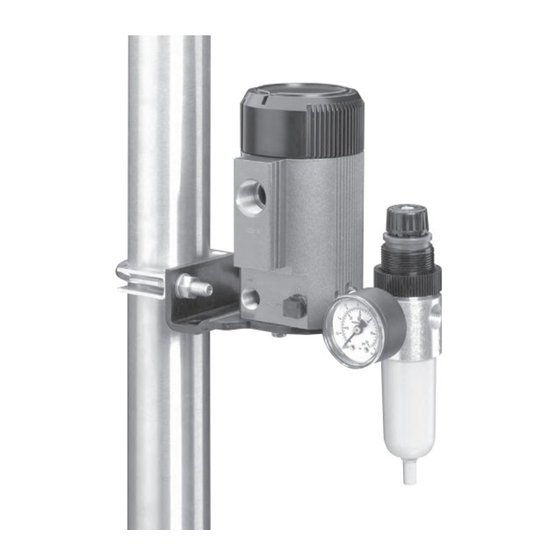
Check the values listed in Table 2. 4. Repeat steps 1 through 3 until IPH outputs 0% of Calibration Process rated pressure range at 0% current input, and 100% of output pressure range at 100% current To perform the recommended bench-check for the input. - Page 7 Figure 2. IPH Current-to-Pressure Transmitter Housing Dimensions CONDUIT WIRE ENTRY METRIC (M20 x 1.5) OR NPT (1/2-14) SCREW-ON CAP THREADS 143 mm (5.6 in) -FR1 OPTION (COALESCING FILTER/REGULATOR AND PRESSURE GAUGE) 85 mm (3.4 in) 157 mm (6.2 in) 21 mm (0.8 in)
-
Page 8: Installation
0.01 micron. This filter removes virtually mounting hardware or other appropriate fasteners. all condensable liquids from the air stream as well. If you have further questions on how to mount the IPH, • Filter/Regulator Module Option – A combined... -
Page 9: Operation
Disassembling the IPH the next section. To disassemble the IPH for maintenance/cleaning, Remember that if an IPH is installed in an open loop, it unscrew the protective top cover, then unscrew the two may appear to drift over extended periods of time screws from the base and remove the unit. -
Page 10: Changing The Pneumatic Block
Cleaning the Pneumatic Block syringe filled with alcohol to flush the openings. Set section #1 aside. Refer to Figure to disassemble the IPH pneumatic block, and when performing the following: 6. Remove spring, disk, and diaphragm from top of section #2. Inspect each for deterioration and dirt. - Page 11 Figure 3. IPH Internal Assemblies MECHANICAL PNEUMATIC SUB-ASSEMBLY BLOCK NOZZLE FLAPPER SECTION #1 ORIFICE #1 UPPER SPRING (HEAVY GAUGE WIRE) PLASTIC DISK HOLE UPPER RUBBER DIAPHRAGM ROLL IS UP BRASS FITTING SECTION #2 ROLL IS DOWN MIDDLE RUBBER DIAPHRAGM HOLE...
-
Page 12: Re-Assembly
2. Use the scratch markings made earlier to make If a problem is suspected with the IPH, review the sure that each section of pneumatic block is following steps: oriented properly, then use small socket-head screws to secure re-assembled block. - Page 13 These diagrams must be used to augment the installa- tion instructions earlier in this manual for units that are This page contains the installation diagram for the IPH to operate in areas requiring intrinsically safe instru- carrying the intrinsically safe option. It also includes mentation.
- Page 14 The following guidelines must be followed in order to comply with EN61010-1 (Low Voltage Directive). Supply Wiring These items affect the AC version of the IPH. If All power connections should be made with the these products are to be used in a non-CE environ- proper wire.
- Page 15 4. Ship the equipment to the Moore Industries location nearest you. The returned equipment will be inspected and tested at the factory. A Moore Industries representative will contact the person designated on your documentation if more information is needed. The repaired equipment, or its replacement, will be returned to you in accordance with the shipping instructions furnished in your documentation.
Need help?
Do you have a question about the IPH and is the answer not in the manual?
Questions and answers