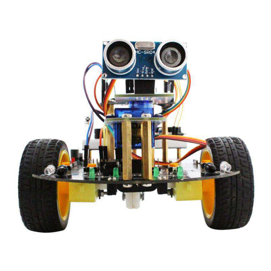
Summary of Contents for YahBoom Smartduino HC-SR04
- Page 1 Smartduino Robots Operation Manual Shenzhen YahBoom Technology Co.,Ltd www.yahboom.com...
- Page 2 Solemnly Declare Shenzhen YahBoom Technology Co.,Ltd. Represent that: I. The procedures and learning materials for this product belong to Shenzhen YahBoomTechnology Co., Ltd. No entity or individual may use the data for commercial purposes without the authorization of the company.
-
Page 3: Table Of Contents
Content 目录 I. Packing List.............................. 1 Arduino Smart Car (Standard Version)....................1 II. Installation For Arduino Smart Car......................2 2.1 Installation for Servo........................2 2.2 Installation for Motor & Wheel....................3 2.3 Installation for Battery Box......................3 2.4 Installation for Copper Pillars...................... 3 2.5 Installation for Universal Wheel.................... -
Page 4: Packing List
I. Packing List Arduino Smart Car (Standard Version) 1. Packing List 1. Arduino UNO Controller * 1 20. Infrared Receiver Module*1 2. Car chassis * 1 21. Active Buzzer * 1 3. Ultrasonic Module * 1 22. Flame Sensor * 1 4. -
Page 5: Installation For Arduino Smart Car
II. Installation For Arduino Smart Car Accessory Introduction M3*8mm Copper M3*40mm Copper Pillar*2 M3*4mm Copper Fixing Support*4 Pillar*7 Pillar*4 Need to take away from the two sides of the car chassis center. M3 Nut*6 M3*8mm M3*6mm M3*30mm Self-tapping Small Screw*1 Screw *2 Screw*2 Screw*4... -
Page 6: Installation For Motor & Wheel
2.2 Installation for Motor & Wheel M3*30 Screw Design Sketch (After Installation) Installation Instruction: The motor fixing support passes through the car chassis, and fixed with screw and nut, then the wheels are mounted on the motors 2.3 Installation for Battery Box M3*8mm Screw Design Sketch (After Installation) -
Page 7: Installation For Universal Wheel
Installation Instruction: Install the fixing copper pillar in the right side of the car chassis, 2pcs M3*40mm copper pillars in the car head, 4pcs M3*45mm copper pillars in the middle, 3pcs M3*8mm copper pillars in the tailstock. Then using M3*6mm screws to fix them at the bottom of the car chassis. -
Page 8: Installation For Arduino Board
2.7 Installation for Arduino board M3*6mm Screw Design Sketch (After Installation) Installation Instruction: Install Arduino board on the 4pcs M3*45mm copper pillars,then fixed by M3*6mm screws. 2.8 Installation for Breadboard M3*6mm Screw Design Sketch (After Installation) Installation Instruction: Install a breadboard holder on the 3pcs M3*8mm copper pillars at tailstock and fixed with screws. -
Page 9: Fuctions Of Usage Intstructions
III. Fuctions of Usage Intstructions Infrared Tracking Mode ①Adjust potentiom 【SW3】to make photoelectric sensor【P3】 against white undersurface, then LED light【L3】illumiinates while against black surface, LED light【L3】goes off. ②Adjust potentiom 【SW4】to make photoelectric sensor【P2】 against white undersurface, then LED light【L2】illumiinates while against black surface, LED light【L2】goes off. Caution:Don’t excessively rotate potentiometer while adjusting. -
Page 10: Wiring Instructions
IV. Wiring Instructions 4.1 Motor drive wiring diagram According to this wiring diagram, the smart car can realize forward, backward, left, right, and specified fancy movements after uploading the corresponding program. -
Page 11: Tracking Wiring Diagram
4.2 Tracking wiring diagram Active buzzer Start button According to the wiring diagram , the smart car can realize the black line tracking function after uploading the corresponding program. Before the experiment, please refer to (III. Fuctions of Usage Intstructions). -
Page 12: Infrared Obstacle Avoidance Wiring Diagram
4.3 Infrared obstacle avoidance wiring diagram Active buzzer Start button According to the wiring diagram, the smart car can realize infrared obstacle avoidance and infrared follow-up functions after uploading the corresponding program. Before the experiment, please refer to (III. Fuctions of Usage Intstructions). -
Page 13: Ultrasonic Obstacle Avoidance(No Servo) Wiring Diagram
4.4 Ultrasonic obstacle avoidance(no servo) wiring diagram Start button Active Buzzer Note: At the J2 slot, insert the ultrasonic sensor as picture. If you only use the ultrasonic obstacle avoidance function without displaying the distance, you can not install the 1602 sdisplay and yellow adjustable resistance. -
Page 14: Ultrasonic Obstacle Avoidance(With Servo) Wiring Diagram
4.5 Ultrasonic obstacle avoidance(with servo) wiring diagram Start button Active Buzzer If you only use the ultrasonic obstacle avoidance function without displaying the distance, you can not install the 1602 sdisplay and yellow adjustable resistance. -
Page 15: Remote Control Wiring Diagram
4.6 Remote control wiring diagram This experiment requires the use of an infrared remote control. Before use, please remove the insulated plastic sheet at the bottom of the remote control. The numbers 2,8,4,6 on the remote control correspond to advance, return back, turn left and ture right; 1,3 corresponds to left and right rotation;... -
Page 16: Tracking & Ultrasonic Wiring Diagram
4.7 Tracking & Ultrasonic wiring diagram Start botton Active buzzer Note: At the J2 slot, insert the ultrasonic sensor as picture. This experiment is a 2in1 comprehensive experiment. The car can detect the obstacles while tracking. When encountering an obstacle, the car stops waiting in place. After clearing obstacle, the car continues to track. -
Page 17: Bluetooth Remote Control Wiring Diagram
4.8 Bluetooth remote control wiring diagram As the Bluetooth module and the serial port of the writer share the IO ports 0 and 1, it will cause failure in burning. Please remove the VCC of the Bluetooth module power supply before burning, and then supply power to the Bluetooth module after finishing. -
Page 18: Operation
Arduino smart car( with bluetooth) 1.Package list Arduino smart car( standard) + Bluetooth module 2.Introdution The Arduino Smart Car (Bluetooth Version) has a Bluetooth module added to the standard configuration. Users can use the APP we provide to perform Bluetooth remote control. The Bluetooth remote control includes controlling the car's front, rear, left and right travel, adjusting the speed, and rotating.


Need help?
Do you have a question about the Smartduino HC-SR04 and is the answer not in the manual?
Questions and answers