
Related Manuals for IFM SD26 Series


Summary of Contents for IFM SD26 Series
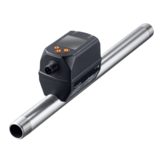
- Page 1 Operating instructions Flow meter compressed air / gases SD25xx SD26xx SD55xx SD56xx SD65xx SD66xx SD85xx SD86xx SD95xx...
-
Page 2: Table Of Contents
Contents 1 Preliminary note ���������������������������������������������������������������������������������������������������5 1�1 Symbols used ������������������������������������������������������������������������������������������������5 1�2 Warnings used �����������������������������������������������������������������������������������������������5 2 Safety instructions �����������������������������������������������������������������������������������������������6 3 Functions and features ����������������������������������������������������������������������������������������7 3�1 Pressure Equipment Directive (PED) ������������������������������������������������������������7 3�2 Applications ���������������������������������������������������������������������������������������������������7 4 Function ���������������������������������������������������������������������������������������������������������������8 4�1 Processing of the measured signals ��������������������������������������������������������������8 4�2 Switching output ��������������������������������������������������������������������������������������������9 4�3 Analogue output �������������������������������������������������������������������������������������������10 4�4 Consumed quantity monitoring [ImP] ����������������������������������������������������������12... - Page 3 8�3 Extended functions (EF) ������������������������������������������������������������������������������24 8�4 Submenu OUT1 �������������������������������������������������������������������������������������������25 8�5 Submenu OUT2 �������������������������������������������������������������������������������������������27 8�6 Submenu CFG ���������������������������������������������������������������������������������������������29 8�7 Submenus MEM, DIS ����������������������������������������������������������������������������������31 8�8 Submenus COLR, SIM ��������������������������������������������������������������������������������33 9 Set-up ����������������������������������������������������������������������������������������������������������������35 10 Parameter setting ��������������������������������������������������������������������������������������������35 10�1 Parameter setting in general ���������������������������������������������������������������������36 10�1�1 Select submenu ��������������������������������������������������������������������������������36 10�1�2 Change to the process value display (RUN mode) ��������������������������36 10�1�3 Lock / unlock �������������������������������������������������������������������������������������36...
- Page 4 10�6�4 Standard unit of measurement for pressure �������������������������������������41 10�6�5 Measured value damping �����������������������������������������������������������������42 10�6�6 Output logic ��������������������������������������������������������������������������������������42 10�6�7 Medium for SDx6xx units ������������������������������������������������������������������42 10�6�8 Low flow cut-off ���������������������������������������������������������������������������������42 10�6�9 Standard conditions ��������������������������������������������������������������������������42 10�6�10 Zero-point calibration pressure �������������������������������������������������������42 10�6�11 Colour of the characters in the display �������������������������������������������43 10�6�12 Switch-on /switch-off delay �������������������������������������������������������������43 10�6�13 Error behaviour of the outputs ��������������������������������������������������������44 10�6�14 Restore factory setting ��������������������������������������������������������������������44...
-
Page 5: Preliminary Note
1 Preliminary note Detailed instructions, technical data, approvals and other information via the QR code on the unit / on the packaging or at www�ifm�com� 1.1 Symbols used ► Instructions > Reaction, result […] Designation of keys, buttons or indications →... -
Page 6: Safety Instructions
2 Safety instructions • The device described is a subcomponent for integration into a system� - The manufacturer is responsible for the safety of the system� - The system manufacturer undertakes to perform a risk assessment and to create a documentation in accordance with legal and normative requirements to be provided to the operator and user of the system�... -
Page 7: Functions And Features
3 Functions and features The unit monitors the standard volume flow of compressed air in industrial use and / or technical gases (→ 3.2 Applications)� It detects the 5 process variables flow velocity, volumetric flow quantity, consumed quantity, medium temperature and pressure� All indications apply to standard volume flow to DIN ISO 2533, i�e�... -
Page 8: Function
4 Function • The volumetric flow is monitored by a calorimetric measuring system, the measured signals are evaluated by the electronics� • The unit detects the pressure and the media temperature of the volumetric flow as additional process values� • The unit features an IO-Link interface •... -
Page 9: 4�2 Switching Output
4.2 Switching output OUTx changes its switching status if it is above or below the set switching limits (flow, temperature or pressure)� Hysteresis or window function can be selected� Example of volumetric flow monitoring: Hysteresis function Window function SP = set point FH = upper limit rP = reset point FL = lower limit... -
Page 10: 4�3 Analogue Output
4.3 Analogue output The unit provides an analogue signal that is proportional to the volumetric flow quantity, the medium temperature or the pressure� Within the measuring range the analogue signal is 4���20 mA� The measuring range is scalable: • [ASP2] determines at which measured value the output signal is 4 mA� •... - Page 11 [mA] FOU=On 21,5 20,5 FOU=OFF cr�UL UL cr�OL [% MEW] [bar] [°C] [°F] Fig� 1: Characteristics of the analogue output according to the standard IEC 60947-5-7� analogue signal measured value (volumetric flow, temperature or pressure) detection zone display range measuring range scaled measuring range flow pressure...
-
Page 12: 4�4 Consumed Quantity Monitoring [Imp]
4.4 Consumed quantity monitoring [ImP] The unit has an internal quantity meter (totaliser)� It continuously sums up the consumed quantity and provides this process value both on the display and via the IO-Link interface� Pulse signals or a switching signal (preset counter) can be used to monitor the consumed quantity�... -
Page 13: 4�4�3 Consumed Quantity Monitoring Via Pulse Signals
4.4.3 Consumed quantity monitoring via pulse signals Every time the flow rate set with [ImPS] has been reached (pulse value), the output provides a pulse signal� OUT1 and OUT2 cannot be used simultaneously for the pulse output� 4.4.4 Consumed quantity monitoring via preset counter When the flow rate set under [ImPS] has been reached, the output provides a switching signal�... -
Page 14: 4�5 Measured Value Damping
4.5 Measured value damping The damping time [dAP�F] und [dAP�P] allows to set after how many seconds the output signal has reached 63 % of the final value if the flow value / the pressure value changes suddenly� The set damping time stabilises the switching outputs, the display and the process value transfer via the IO-Link interface�... -
Page 15: 4�8 Colour Of The Characters In The Display
4.8 Colour of the characters in the display The colour of the characters in the display can be set via the parameter [coL�x]: • Permanent definition of the display colour: - bk/wh (black/white) - yellow - green - red • Colour change from red to green or vice versa (Fig� 2): - r-cF (red display colour between the limits cFL���cFH) - G-cF (green display colour between the limits cFL���cFH) cFL = lower limit... -
Page 16: 4�9 Io-Link
IO-Link hardware and software can be found at www�ifm�com� 4.9.1 Additional functions via IO-Link The following functions are only available via the IO-Link interface by means of a... -
Page 17: 5�1 Installation Location
5.1 Installation location ► Install the unit downstream of the cold dryer� ► Install the unit near the load� ► The unit can be installed downstream of a maintenance unit� ► If oil is used for the loads: install the unit upstream of the oiler� 5.2 Installation position 5.2.1 Inlet and outlet pipe lengths Structures in the pipe, bends, valves, reducing pieces and the like affect the... -
Page 18: 5�2�2 Orientation
5.2.2 Orientation Fig� 1: Orientation of the pipe length and the unit 1: pipe length vertical, unit any 2: pipe length horizontal, unit vertical 3: pipe length right, unit on side 4: avoid: pipe length left, unit on side 5.3 Installation in pipes ►... -
Page 19: Electrical Connection
Type Tightening torque SD5xxx 50 Nm SD6xxx, SD8xxx 100 Nm SD2xxx, SD9xxx 150 Nm 6 Electrical connection The device must be connected by a qualified electrician� Voltage supply according to EN 50178, SELV, PELV� ► Disconnect power� ► Connect the unit as follows: OUT2 OUT1 Colours to DIN EN 60947-5-2... - Page 20 Circuit examples: 2 x positive switching 2 x negative switching 1 BN 1 BN 2 WH 2 WH 4 BK 4 BK 3 BU 3 BU 1 x positive switching / 1 x analogue 1 x negative switching / 1 x analogue 1 BN 1 BN 2 WH...
-
Page 21: Operating And Display Elements
7 Operating and display elements 1 and 2: Switching status LEDs • LED 1 = switching status OUT1 (on if output 1 is switched) • LED 2 = switching status OUT2 (on if output 2 is switched) 3: TFT display •... -
Page 22: Menu
8 Menu 8.1 Process value display (RUN) It is possible to select three process value indications during operation: ► Press [▲] or [▼]. > The display changes between the standard indication and two other views� > After 30 s, the device returns to the standard display� Running���... -
Page 23: 8�2 Main Menu
8.2 Main menu Process value display (RUN) ImPS1 ImPR1 ASP2 ImPS2 DIn2 AEP2 ImPR2 rES, rTo, Info, OUT1, OUT2, CFG, TOTL, MEM, DIS, COLR, SIM Explanation of the parameters → 8.4 Submenu OUT1 and → 8.5 Submenu OUT2 The displayed parameters change when the factory setting in submenu OUT1 and OUT2 is changed�... -
Page 24: 8�3 Extended Functions
8.3 Extended functions (EF) Main menu Parameter Explanation and setting options - - - - restore factory setting rES.T reset of the totaliser 2 h 3 h 4 h 5 h ... Info display device information - - - - Info OUT1 configuration output 1... -
Page 25: 8�4 Submenu Out1
8.4 Submenu OUT1 Main menu SEL1 FLOW TEMP PRES Hno Hnc Fno Fnc ImP OFF Info OUT1 ImPS1 OUT2 ImPR1 OUT1 FOU1 OU On OFF COLR... - Page 26 Explanations submenu OUT1 Parameter Explanation and setting options SEL1 standard unit of measurement for evaluation by OUT1: FLOW (volumetric flow) or TEMP (temperature) or PRES (pressure) output function for OUT1: • flow Hno, Hnc, Fno, Fnc, ImP • temperature: Hno, Hnc, Fno, Fnc •...
-
Page 27: 8�5 Submenu Out2
8.5 Submenu OUT2 Main menu Info OUT1 SEL2 FLOW TEMP PRES OUT2 Hno Hnc Fno Fnc In.D ASP2 ImPS2 DIn2 AEP2 ImPR2 COLR OUT2 FOU2 OU On OFF The displayed parameters change when the factory setting in submenu OUT2 is changed�... - Page 28 Explanation submenu OUT2 Parameter Explanation and setting options SEL2 standard measured variable for evaluation by OUT2: FLOW (volumetric flow) or TEMP (temperature) or PRES (pressure) output function for OUT2: • flow Hno, Hnc, Fno, Fnc, I, ImP • temperature: Hno, Hnc, Fno, Fnc, I •...
-
Page 29: 8�6 Submenu Cfg
8.6 Submenu CFG Main menu uni.F l/min m/s ft /h ft /m ft/s uni.T °C °F Info uni.P kPa bar psi OUT1 - - - dAP.F OUT2 - - - dAP.P PnP nPn MEdi Ar CO2 N2 AIR - - - - - - rEF.P COLR... - Page 30 Explanation submenu CFG Parameter Explanation and setting options uni�F standard unit of measurement for volumetric flow uni�T standard unit of measurement for temperature uni�P standard unit of measurement for pressure dAP�F measured value damping for volumetric flow dAP�P measured value damping for pressure output logic MEdi medium selection (only available for SDx6xx)
-
Page 31: 8�7 Submenus Mem, Dis
8.7 Submenus MEM, DIS Main menu Lo�F ��� Hi�F ��� ��� Lo�T Info Hi�T ��� OUT1 ��� Lo�P OUT2 ��� Hi�P diS�L L2�Temp L2�Pres L2.Totl L3�TP COLR diS�U d1 d2 d3 diS�R 0 90 180 270 diS�B 25 50 75 100 OFF... - Page 32 Explanation submenu MEM Parameter Explanation and setting options Lo�F min� value of the flow volume measured in the process Hi�F max� value of the flow volume measured in the process Lo�T min� value of the temperature measured in the process Hi�T max�...
-
Page 33: 8�8 Submenus Colr, Sim
8.8 Submenus COLR, SIM Main menu coL�F bk/wh red green yellow r-cF G-cF - - - cFH�F - - - cFL�F coL�T bk/wh red green yellow r-cF G-cF Info - - - cFH�T OUT1 - - - cFL�T OUT2 coL�P bk/wh red green yellow r-cF G-cF - - - cFH�P... - Page 34 Explanation submenu COLR The displayed parameters change when the factory setting in submenu OUT1 and OUT2 is changed� Parameter Explanation and setting options coL�F colour of the characters in the display for the flow rate value cFH�F upper limit of the colour change for flow rate measurement cFL�F lower limit of the colour change for flow rate measurement coL�T...
-
Page 35: Set
9 Set-up After power on and expiry of the power-on delay time of approx� 1 s, the unit is in the Run mode (= normal operating mode)� It carries out its measurement and eval- uation functions and generates output signals according to the set parameters� •... -
Page 36: 10�1 Parameter Setting In General
10.1 Parameter setting in general 1� Change from the RUN mode to the main menu [●] 2� Select the requested parameter [▲] or [▼] 3� Change to the setting mode [●] 4� Change the parameter value [▲] or [▼] > 1 s 5�... -
Page 37: 10�1�4 Timeout
During operation: [�� Lock via key] is displayed if you try to change param- eter values� Unlocking: ► Make sure that the unit is in the normal operating mode� ► Press [▲] and [▼] simultaneously for 10 s until [Reset menu lock] is displayed. 10.1.4 Timeout If no button is pressed for 30 s during parameter setting, the unit returns to the operating mode with unchanged values�... -
Page 38: 10�3 Settings For Consumed Quantity Monitoring
10.3 Settings for consumed quantity monitoring 10.3.1 Quantity monitoring by pulse signal OUT1 or OUT2 ► Select [SELx] and set FLOW� Menu OUTx: ► Select [oux] and adjust the pulse output: ImP [SELx] ► Select [ImPSx] and set pulse value (= volumetric flow quantity at which [oux] a pulse is provided): [ImPSx]... -
Page 39: 10�3�6 Counter Reset Using An External Signal
10.3.6 Counter reset using an external signal ► Select [ou2] and set In.D. Menu OUT2: ► Select [DIn2] and set counter reset signal: [ou2] [DIn2] - HIGH = reset for high signal - LOW = reset for low signal - +EDG = reset for rising edge - –EDG = reset for falling edge >... -
Page 40: 10�5 Settings For Pressure Monitoring
10.5 Settings for pressure monitoring 10.5.1 Limit monitoring OUT1 or OUT2 / hysteresis function ► Select [SELx] and set PRES� Menu OUTx: ► Select [oux] and adjust the switching signal: [SELx] [oux] - Hno = hysteresis function / normally open - Hnc = hysteresis function / normally closed [SPx] [rPx]... -
Page 41: 10�6 User Settings (Optional)
10.6 User settings (optional) 10.6.1 Standard display ► Select [diS�L] and set process value display: Menu DIS: [diS�L] - L1 = current process value for volumetric flow [diS�U] - L2�Temp = current process value for flow and temperature [diS�R] - L2�Pres = current process value for volumetric flow and pressure - L2�Totl = current process value for volumetric flow and totaliser... -
Page 42: 10�6�5 Measured Value Damping
10.6.5 Measured value damping ► Select [dAP�F] for flow rate measurement or [dAP�P] for pressure Menu CFG: measurement and set damping constant in seconds (τ value 63 %). [dAP�x] 10.6.6 Output logic ► Select [P-n] and set PnP or nPn� Menu CFG: [P-n] 10.6.7 Medium for SDx6xx units... -
Page 43: 10�6�11 Colour Of The Characters In The Display
10.6.11 Colour of the characters in the display ► Select [coL�F] for volumetric flow or [coL�T] for temperature or [col�P] for Menu COLR: pressure and set the colour of the characters for the process value in [coL�x] the standard display: [cFH�x] [cFL�x] - bk/wh = permanently black/white... -
Page 44: 10�6�13 Error Behaviour Of The Outputs
10.6.13 Error behaviour of the outputs ► Select [FOU1] and set error behaviour for output 1: Menu OUT1: [FOU1] switching output - On = output 1 switches ON in case of an error Menu OUT2: - OFF = output 1 switches OFF in case of an error [FOU2] - OU = output 1 switches irrespective of the error as defined with the... -
Page 45: 10�7 Diagnostic Functions
10.7 Diagnostic functions 10.7.1 Read min/max values ► Select [Lo�x] or [Hi�x] to display the highest or lowest process value Menu MEM: measured: [Lo�x] [Hi�x] - [Lo�F] = min� value of the flow volume measured in the process - [Hi�F] = max� value of the flow volume measured in the process - [Lo�T] = min�... -
Page 46: Operation
If several diagnostic events occur simultaneously, only the diagnostic message of the result with the highest priority is displayed� If one process value fails, the other process values continue to be available� Additional diagnostic functions are available via IO-Link → IODD interface description at www�ifm�com Description Error correction ERROR ERROR Unit faulty / mal- FOU Replace device�... - Page 47 Description Error correction ERROR Flow Error in flow meas- FOU Check flow meas- Error urement urement� Replace device� ERROR Temp Error in temperature FOU Check temperature Error measurement measurement� Re- place device� cr�OL Critical Detection zone* FOU Check flow range / over exceeded temperature range /...
-
Page 48: Maintenance, Repair And Disposal
Description Error correction Lock via Parameter setting Finish parameter commu- locked via push- setting via IO-Link nication buttons, parameter communication� setting is active via IO-Link communi- cation Lock via Setting buttons Unlock the unit via system locked via parameter IO-Link interface software, parameter using the parameter change rejected... -
Page 49: Factory Setting
14 Factory setting Menu Parameter Factory setting User setting OUT1 SEL1 FLOW SP1 / FH1 20 % rP1 / FL1 19 % ImPS1 SD5, SD6: 0�0001 m SD8, SD9, SD2: 0�001 m ImPR1 FOU1 OUT2 SEL2 FLOW ASP2 AEP2 100 % SP2 / FH2 40 % rP2 / FL2... - Page 50 Menu Parameter Factory setting User setting uni.F uni.T SDx500, SDx600: °C SDx501, SDx601: °F uni.P SDx500, SDx6xx: bar SDx501, SDx601: psi dAP.F 0�6 s dAP.P 0�06 s MEdi * SD5: 0�02 m SD6: 0�1 m SD8: 0�3 m SD9: 0�5 m SD2: 2 m rEF.P 1013 mbar...
Need help?
Do you have a question about the SD26 Series and is the answer not in the manual?
Questions and answers