Table of Contents
Advertisement
Quick Links
Advertisement
Table of Contents

Subscribe to Our Youtube Channel
Related Manuals for IFM SV0527


Summary of Contents for IFM SV0527
- Page 1 Operating instructions Vortex flow meter SV0527 SV0528 SV0529...
-
Page 2: Table Of Contents
SV0527 SV0528 SV0529 Vortex flow meter Contents Preliminary note ............. -
Page 3: Preliminary Note
Vortex flow meter SV0527 SV0528 SV0529 1 Preliminary note You will find instructions, technical data, approvals and further information using the QR code on the unit / packaging or at www.ifm.com. 1.1 Symbols used Requirement Instructions Reaction, result [...] Designation of keys, buttons or indications... -
Page 4: Safety Instructions
SV0527 SV0528 SV0529 Vortex flow meter 2 Safety instructions • The unit described is a subcomponent for integration into a system. – The system architect is responsible for the safety of the system. – The system architect undertakes to perform a risk assessment and to create documentation in accordance with legal and normative requirements to be provided to the operator and user of the system. -
Page 5: Intended Use
Vortex flow meter SV0527 SV0528 SV0529 3 Intended use The unit monitors liquid media. The unit detects the process categories volume flow (volumetric flow quantity/time) and medium temperature. 3.1 Application area • Water • Hydrous media (deionised water, cooling water) Pressure Equipment Directive (PED): The units comply with the Pressure Equipment Directive and are designed and manufactured for group 2 fluids in accordance with the sound engineering practice. -
Page 6: Function
SV0527 SV0528 SV0529 Vortex flow meter 4 Function • The device detects flow based on the Vortex measuring principle. • As additional process value the unit detects the medium temperature. • The unit displays the current process values. • The device can be operated in SIO mode (standard input-output ) or in IO-Link mode. The basic operation mode is SIO. -
Page 7: Installation
Vortex flow meter SV0527 SV0528 SV0529 5 Installation CAUTION If the medium temperature is above 50 °C (122 °F), parts of the housing can increase in temperature to over 65 °C (149 °F). w Risk of burns. u Protect the housing against contact with flammable substances and unintentional contact. -
Page 8: Non Recommended Installation Position
SV0527 SV0528 SV0529 Vortex flow meter Information about available accessories at www.ifm.com 5.1 Non recommended installation position • Directly in front of a falling pipe. • In a falling pipe. • Directly in front of the spout of a pipe. •... -
Page 9: Electrical Connection
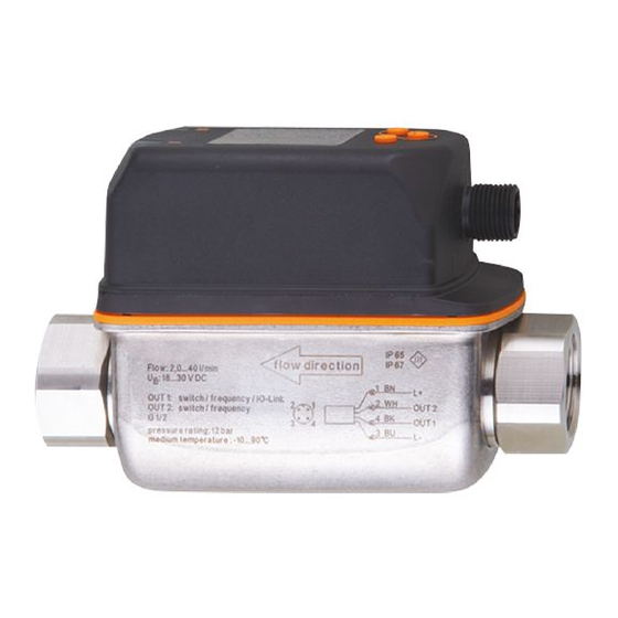
Vortex flow meter SV0527 SV0528 SV0529 6 Electrical connection The unit must be connected by a qualified electrician. Observe the national and international regulations for the installation of electrical equipment. Voltage supply according to SELV, PELV. u Disconnect power. u Connect the unit as follows:... -
Page 10: Operating And Display Elements
SV0527 SV0528 SV0529 Vortex flow meter 7 Operating and display elements Switching status LED for OUT1 Switching status LED for OUT2 TFT display Keys for changing views and parameter setting Fig. 3: Operating and display elements... -
Page 11: Menu
Vortex flow meter SV0527 SV0528 SV0529 8 Menu The figures in which the menus are displayed show the parameters that can be set on the unit by key input. These parameters and other functions are also available via the IO-Link interface. - Page 12 SV0527 SV0528 SV0529 Vortex flow meter Parameter Explanation FSPx Frequency start point for OUTx = Lower measured value from which a frequency signal is output (only for temperature measurement). FEPx Frequency end point for OUTx = Upper measured value at which the frequency signal set under FrPx is output.
- Page 13 Vortex flow meter SV0527 SV0528 SV0529 Main menu ---- Lo.F Info ---- Hi.F ---- Lo.T ---- Hi.T Fig. 7: Memory [MEM] menu Parameter Explanation Lo.F Lowest flow value measured Hi.F Highest flow value measured Lo.T Minimum measured temperature value Hi.T Maximum temperature value measured...
- Page 14 SV0527 SV0528 SV0529 Vortex flow meter Parameter Explanation col.T Font colour for temperature cFH.T Upper limit value for colour change (temperature) cFL.T Lower limit value for colour change (temperature)
-
Page 15: Parameter Setting
> 30 seconds (timeout) 9.2 Parameter setting via IO-Link Requirements for parameter setting via the IO-Link interface: ü A suitable parameter setting software, e.g. ifm moneo|configure ü The Input Output Device Description (IODD) for the device, see documentation.ifm.com ü One IO-Link master u Connect the IO-Link master to a parameter setting software. - Page 16 SV0527 SV0528 SV0529 Vortex flow meter u Change parameter settings in the software. u Write parameter settings to the unit. Notes on parameter setting Ò Manual of the parameter setting software...
-
Page 17: Factory Setting
Vortex flow meter SV0527 SV0528 SV0529 10 Factory setting Parameter Factory setting User setting SP1 (FLOW) 20 % MEW rP1 (FLOW) 18.5 % MEW FH1 (FLOW) 20 % MEW FL1 (FLOW) 18.5 % MEW FEP1 (FLOW) 100 % MEW FrP1 (FLOW)
Need help?
Do you have a question about the SV0527 and is the answer not in the manual?
Questions and answers