Table of Contents
Advertisement
Quick Links
Advertisement
Table of Contents

Related Manuals for IFM SM6x04


Summary of Contents for IFM SM6x04
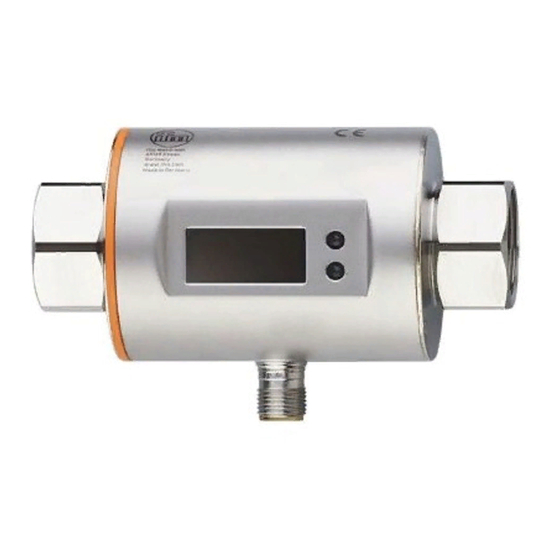
- Page 1 Operating instructions Magnetic-inductive flow meter SM6x04 SM7x04 SM8x04...
-
Page 2: Table Of Contents
Contents 1 Preliminary note ���������������������������������������������������������������������������������������������������3 2 Safety instructions �����������������������������������������������������������������������������������������������3 3 Functions and features ����������������������������������������������������������������������������������������4 4 Function ���������������������������������������������������������������������������������������������������������������5 4�1 Processing of the measured signals ��������������������������������������������������������������5 4�2 Direction of flow ���������������������������������������������������������������������������������������������5 4�3 Analogue function ������������������������������������������������������������������������������������������6 4�4 Measured value damping (dAP) ��������������������������������������������������������������������7 5 Mounting ��������������������������������������������������������������������������������������������������������������8 5�1 Recommended installation position ���������������������������������������������������������������8 5�2 Not recommended installation position ����������������������������������������������������������9 5�3 Grounding ����������������������������������������������������������������������������������������������������10... -
Page 3: Preliminary Note
10�5�2 Restoring the factory settings �����������������������������������������������������������19 11 Operation ���������������������������������������������������������������������������������������������������������19 11�1 Reading the process value ������������������������������������������������������������������������19 11�2 Changing the process value display in the RUN mode������������������������������20 11�3 Reading the set parameters �����������������������������������������������������������������������20 12 Troubleshooting �����������������������������������������������������������������������������������������������21 13 Technical data ��������������������������������������������������������������������������������������������������21 14 Factory setting ������������������������������������������������������������������������������������������������22 1 Preliminary note ►... -
Page 4: Functions And Features
• Read this document before setting up the product and keep it during the entire service life� • The product must be suitable for the corresponding applications and environ- mental conditions without any restrictions� • Only use the product for its intended purpose (→ Functions and features). •... -
Page 5: Function
4 Function • The unit detects the flow based on the magnetic-inductive volumetric flow measuring principle� • The unit also detects the medium temperature� • The unit displays the current process value� 4.1 Processing of the measured signals The unit generates 2 output signals according to the parameter settings: OUT1: Parameter setting - Analogue signal for temperature... -
Page 6: 4�3 Analogue Function
4.3 Analogue function • The unit provides an analogue signal that is proportional to the volumetric flow quantity and the medium temperature� • Within the measuring range the analogue signal is 4���20 mA� • If the measured value is outside the measuring range or in the event of an internal error, the current signals indicated in Figure 1 are provided�... -
Page 7: 4�4 Measured Value Damping (Dap)
Flow (a negative flow value means flow against the marked flow direction) Temperature Below the display range Above the display range Err: The unit is in the error state FOU=On: Default setting at which the analogue signal goes to the upper final value in case of an error�... -
Page 8: Mounting
5 Mounting CAUTION If the medium temperature is above 50 °C (122 °F) parts of the housing can increase in temperature to over 65 °C (149 °F)� > Risk of burns� ► Protect the housing against contact with flammable substances and unintentional contact�... -
Page 9: 5�2 Not Recommended Installation Position
► Install in front of or in a rising pipe� 5.2 Not recommended installation position ► Avoid the following installation positions: Directly in front of a falling pipe� In a falling pipe�... -
Page 10: 5�3 Grounding
At the highest point of the pipe system� F = flow direction 5.3 Grounding If installed in an ungrounded pipe system (e�g� plastic pipes), the unit must be grounded (functional earth)� Ground brackets for the M12 connector are available as accessories → www.ifm.com. -
Page 11: 5�4 Installation In Pipes
5.4 Installation in pipes The units with a G thread can be installed in the pipes using adapters� Information about the available mounting accessories at www�ifm�com� A correct fit of the unit and ingress resistance of the connection are only ensured using ifm adapters�... -
Page 12: Electrical Connection
6 Electrical connection The unit must be connected by a qualified electrician� The national and international regulations for the installation of electrical equipment must be adhered to� Voltage supply according to EN 50178, SELV, PELV� ► Disconnect power� ► Connect the unit as follows: BK: black BN: brown OUT2... -
Page 13: Operating And Display Elements
7 Operating and display elements 1-8: Indicator LEDs • LEDs 1-6: Unit of the currently represented numerical value → 11.1 Reading the process value • LED 7-8: not used 9: Alphanumeric display, 4 digits • Current volumetric flow quantity with setting [SELd] = FLOW •... -
Page 14: Menu
8 Menu Hi.F l/min °C / °F °C / °F Lo.F Hi.T ASP1 Lo.T FOU1 AEP1 FOU2 ASP2 AEP2 uni.F uni.T SELd [Mode / Enter] [Set]... - Page 15 Parameters Explanation and setting options ASP1 Analogue start point for temperature on OUT1� AEP1 Analogue end point for temperature on OUT1� ASP2 Analogue start point for volumetric flow on OUT2� AEP2 Analogue end point for volumetric flow on OUT2� EF Extended functions: opening of the lower menu level� Hi�F Maximum value memory for volumetric flow�...
-
Page 16: Set
9 Set-up After power on and expiry of the power-on delay time of approx� 5 s the unit is in the RUN mode (= normal operating mode)� It carries out its measurement and evaluation functions and generates output signals according to the set parame- ters�... -
Page 17: 10�1 Parameter Setting In General
10.1 Parameter setting in general 1� Change from the RUN mode to the main menu and [Mode/Enter] selection of the requested parameter 2� Acknowledge the set parameter value [Set] 3� Change the setting mode [Set] > 5 s 4� Modification of the parameter value [Set] - incrementally by pressing once - continuously by keeping the button pressed... -
Page 18: 10�1�3 Timeout
10.1.3 Timeout If no button is pressed for 30 s during parameter setting, the unit returns to the operating mode with unchanged values� 10.2 Scaling of the analogue value for temperature (OUT1) ► Select [ASP1] and set the value at which 4 mA is provided� ►... -
Page 19: 10�4�5 Error Behaviour Of The Outputs
10.4.5 Error behaviour of the outputs ► Select [FOUx] and set the value: - On = The analogue signal goes to the upper fault value (→ 4.3)� - OFF = The analogue value goes to the lower fault value (→ 4.3)� - OU = The analogue signal corresponds to the measured value�... -
Page 20: 11�2 Changing The Process Value Display In The Run Mode
11.2 Changing the process value display in the RUN mode ► Briefly press [Set] in the RUN mode� Press the pushbutton to move to the next display unit� > The unit displays the current measured value in the selected display unit for approx�... -
Page 21: Troubleshooting
► Check flow range / • Current value between temperature range� 120 % ��� 130 % MEW • Temperature value between 100���110 °C (212���230 °F)� MEW = final value of the measuring range 13 Technical data Technical data and scale drawing at www�ifm�com�... -
Page 22: Factory Setting
SMx604 : gpm uni.T SMxx04 : °C SMx404 : °C SMx604 : °F SELd FLOW MAW = Initial value of the measuring range MEW = Final value of the measuring range Technical data, approvals, accessories and further information at www�ifm�com�...
Need help?
Do you have a question about the SM6x04 and is the answer not in the manual?
Questions and answers