Table of Contents
Advertisement
Quick Links
Advertisement
Table of Contents

Related Manuals for IFM SD6020


Summary of Contents for IFM SD6020
- Page 1 Operating instructions Flow meter compressed air SD6020...
-
Page 2: Table Of Contents
Contents 1 Preliminary note ���������������������������������������������������������������������������������������������������4 1�1 Symbols used ������������������������������������������������������������������������������������������������4 1�2 Warnings used �����������������������������������������������������������������������������������������������4 2 Safety instructions �����������������������������������������������������������������������������������������������5 3 Functions and features ����������������������������������������������������������������������������������������6 3�1 Pressure Equipment Directive (PED) ������������������������������������������������������������6 4 Function ���������������������������������������������������������������������������������������������������������������7 4�1 Processing of the measured signals ��������������������������������������������������������������7 4�2 Switching output ��������������������������������������������������������������������������������������������8 4�3 Analogue output ���������������������������������������������������������������������������������������������9 4�4 Consumed quantity monitoring [ImP] ����������������������������������������������������������... - Page 3 8�4 Submenu OUT1 �������������������������������������������������������������������������������������������24 8�5 Submenu OUT2 �������������������������������������������������������������������������������������������26 8�6 Submenu CFG ���������������������������������������������������������������������������������������������28 8�7 Submenus MEM, DIS ����������������������������������������������������������������������������������30 8�8 Submenus COLR, SIM ��������������������������������������������������������������������������������32 9 Set-up ����������������������������������������������������������������������������������������������������������������34 10 Parameter setting ��������������������������������������������������������������������������������������������34 10�1 Parameter setting in general ���������������������������������������������������������������������35 10�1�1 Select submenu ��������������������������������������������������������������������������������35 10�1�2 Change to the process value display (RUN mode) ��������������������������35 10�1�3 Lock / unlock �������������������������������������������������������������������������������������35 10�1�4 Timeout ���������������������������������������������������������������������������������������������36 10�2 Settings for volumetric flow monitoring ������������������������������������������������������36...
-
Page 4: Preliminary Note
13 Maintenance, repair and disposal ��������������������������������������������������������������������46 14 Factory setting �������������������������������������������������������������������������������������������������47 1 Preliminary note Detailed instructions, technical data, approvals and other information via the QR code on the unit / on the packaging or at www�ifm�com� 1.1 Symbols used ► Instructions >... -
Page 5: Safety Instructions
2 Safety instructions • The device described is a subcomponent for integration into a system� - The manufacturer is responsible for the safety of the system� - The system manufacturer undertakes to perform a risk assessment and to create a documentation in accordance with legal and normative requirements to be provided to the operator and user of the system�... -
Page 6: Functions And Features
3 Functions and features The unit monitors the standard volume flow of compressed air in industrial use� It detects the 4 process variables flow velocity, volumetric flow quantity, consumed quantity and medium temperature� All indications apply to standard volume flow to DIN ISO 2533, i�e� volume flow at 1013 mbar, 15 °C and 0 % relative air humidity�... -
Page 7: Function
4 Function • The volumetric flow is monitored by a calorimetric measuring system, the measured signals are evaluated by the electronics� • The unit detects the media temperature of the volumetric flow as additional process value� • The unit features an IO-Link interface •... -
Page 8: 4�2 Switching Output
4.2 Switching output OUTx changes its switching status if it is above or below the set switching limits (flow or temperature)� Hysteresis or window function can be selected� Example of volumetric flow monitoring: Hysteresis function Window function SP = set point FH = upper limit rP = reset point FL = lower limit... -
Page 9: 4�3 Analogue Output
4.3 Analogue output The unit provides an analogue signal that is proportional to the volumetric flow quantity or the medium temperature� Within the measuring range the analogue signal is 4���20 mA� The measuring range is scalable: • [ASP2] determines at which measured value the output signal is 4 mA� •... - Page 10 [mA] FOU=On 21,5 20,5 FOU=OFF cr.UL UL cr.OL [% MEW] [°C] [°F] Fig� 1: Characteristics of the analogue output according to the standard IEC 60947-5-7� analogue signal measured value (volumetric flow or temperature) detection zone display range measuring range scaled measuring range flow temperature MAW: initial value of the measuring range for non-scaled measuring range (With setting of a...
-
Page 11: 4�4 Consumed Quantity Monitoring [Imp]
4.4 Consumed quantity monitoring [ImP] The unit has an internal quantity meter (totaliser)� It continuously sums up the consumed quantity and provides this process value both on the display and via the IO-Link interface� Pulse signals or a switching signal (preset counter) can be used to monitor the consumed quantity�... -
Page 12: 4�4�3 Consumed Quantity Monitoring Via Pulse Signals
4.4.3 Consumed quantity monitoring via pulse signals Every time the flow rate set with [ImPS] has been reached (pulse value), the output provides a pulse signal� OUT1 and OUT2 cannot be used simultaneously for the pulse output� 4.4.4 Consumed quantity monitoring via preset counter When the flow rate set under [ImPS] has been reached, the output provides a switching signal�... -
Page 13: 4�5 Measured Value Damping
4.5 Measured value damping The damping time [dAP�F] allows to set after how many seconds the output signal has reached 63 % of the final value if the flow value changes suddenly� The set damping time stabilises the switching outputs, the display and the process value transfer via the IO-Link interface�... -
Page 14: 4�8 Colour Of The Characters In The Display
4.8 Colour of the characters in the display The colour of the characters in the display can be set via the parameter [coL�x]: • Permanent definition of the display colour: - bk/wh (black/white) - yellow - green - red • Colour change from red to green or vice versa (Fig� 2): - r-cF (red display colour between the limits cFL���cFH) - G-cF (green display colour between the limits cFL���cFH) cFL = lower limit... -
Page 15: 4�9 Io-Link
IO-Link hardware and software can be found at www�ifm�com� 4.9.1 Additional functions via IO-Link The following functions are only available via the IO-Link interface by means of a... -
Page 16: 5�1 Installation Location
5.1 Installation location ► Install the unit downstream of the cold dryer� ► Install the unit near the load� ► The unit can be installed downstream of a maintenance unit� ► If oil is used for the loads: install the unit upstream of the oiler� 5.2 Installation position 5.2.1 Inlet and outlet pipe lengths Structures in the pipe, bends, valves, reducing pieces and the like affect the... -
Page 17: 5�2�2 Orientation
5.2.2 Orientation Fig� 1: Orientation of the pipe length and the unit 1: pipe length vertical, unit any 2: pipe length horizontal, unit vertical 3: pipe length right, unit on side 4: avoid: pipe length left, unit on side 5.3 Installation in pipes ►... -
Page 18: Electrical Connection
6 Electrical connection The device must be connected by a qualified electrician� Voltage supply according to EN 50178, SELV, PELV� ► Disconnect power� ► Connect the unit as follows: OUT2 OUT1 Colours to DIN EN 60947-5-2 BK: black; BN: brown; BU: blue; WH: white Connection •... - Page 19 Circuit examples: 2 x positive switching 2 x negative switching 1 BN 1 BN 2 WH 2 WH 4 BK 4 BK 3 BU 3 BU 1 x positive switching / 1 x analogue 1 x negative switching / 1 x analogue 1 BN 1 BN 2 WH...
-
Page 20: Operating And Display Elements
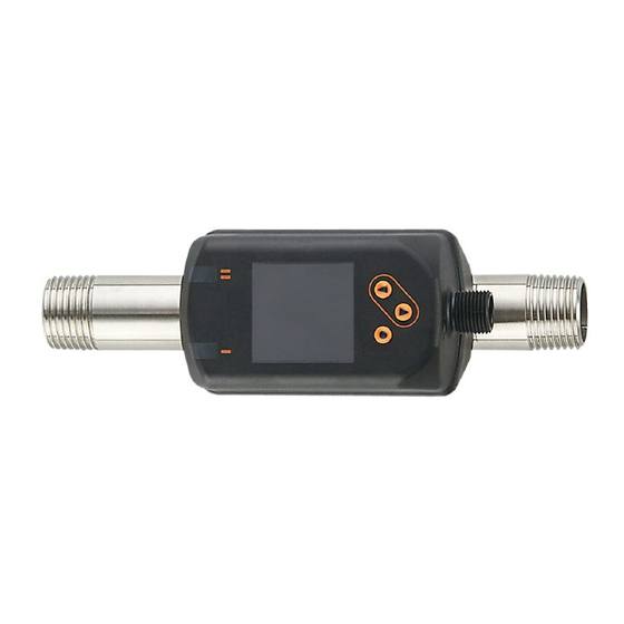
7 Operating and display elements 1 and 2: Switching status LEDs • LED 1 = switching status OUT1 (on if output 1 is switched) • LED 2 = switching status OUT2 (on if output 2 is switched) 3: TFT display •... -
Page 21: Menu
8 Menu 8.1 Process value display (RUN) It is possible to select three process value indications during operation: ► Press [▲] or [▼]. > The display changes between the standard indication and two other views� > After 30 s, the device returns to the standard display� Running... -
Page 22: 8�2 Main Menu
8.2 Main menu Process value display (RUN) ImPS1 ImPR1 ASP2 ImPS2 DIn2 AEP2 ImPR2 rES, rTo, Info, OUT1, OUT2, CFG, MEM, DIS, COLR, SIM Explanation of the parameters → 8.4 Submenu OUT1 and → 8.5 Submenu OUT2 The displayed parameters change when the factory setting in submenu OUT1 and OUT2 is changed�... -
Page 23: 8�3 Extended Functions
8.3 Extended functions (EF) Main menu Parameter Explanation and setting options - - - - restore factory setting rES.T reset of the totaliser 2 h 3 h 4 h 5 h ... Info display device information - - - - Info OUT1 configuration output 1... -
Page 24: 8�4 Submenu Out1
8.4 Submenu OUT1 Main menu SEL1 FLOW TEMP Hno Hnc Fno Fnc ImP OFF Info OUT1 ImPS1 OUT2 ImPR1 OUT1 FOU1 OU On OFF COLR... - Page 25 Explanations submenu OUT1 Parameter Explanation and setting options SEL1 standard unit of measurement for evaluation by OUT1: FLOW (volumetric flow) or TEMP (temperature) output function for OUT1: • flow Hno, Hnc, Fno, Fnc, ImP • temperature: Hno, Hnc, Fno, Fnc Hno = switching signal with hysteresis function normally open Hnc = switching signal with hysteresis function normally closed Fno = switching signal with window function normally open...
-
Page 26: 8�5 Submenu Out2
8.5 Submenu OUT2 Main menu Info OUT1 SEL2 FLOW TEMP OUT2 Hno Hnc Fno Fnc In.D ASP2 ImPS2 DIn2 AEP2 ImPR2 COLR OUT2 FOU2 OU On OFF... - Page 27 Explanation submenu OUT2 Parameter Explanation and setting options SEL2 standard measured variable for evaluation by OUT2: FLOW (volumetric flow) or TEMP (temperature) output function for OUT2: • flow Hno, Hnc, Fno, Fnc, I, ImP • temperature: Hno, Hnc, Fno, Fnc, I Hno = switching signal with hysteresis function normally open Hnc = switching signal with hysteresis function normally closed Fno = switching signal with window function normally open...
-
Page 28: 8�6 Submenu Cfg
8.6 Submenu CFG Main menu uni.F l/min m/s ft /h ft /min ft/s uni.T °C °F Info - - - dAP.F OUT1 PnP nPn OUT2 - - - - - - rEF.P - - - rEF.T - - - SySP COLR... - Page 29 Explanation submenu CFG Parameter Explanation and setting options uni�F standard unit of measurement for volumetric flow uni�T standard unit of measurement for temperature dAP�F measured value damping for volumetric flow output logic low flow cut-off rEF�P standard pressure to which the measured and display values for volumet- ric flow refer rEF�T standard temperature to which the measured and display values for...
-
Page 30: 8�7 Submenus Mem, Dis
8.7 Submenus MEM, DIS Main menu Lo.F Info Hi.F OUT1 Lo.T OUT2 Hi.T diS.L L2.Temp L2.Totl diS.U d1 d2 d3 COLR diS.R 0 90 180 270 diS.B 25 50 75 100 OFF... - Page 31 Explanation submenu MEM Parameter Explanation and setting options Lo�F min� value of the flow volume measured in the process Hi�F max� value of the flow volume measured in the process Lo�T min� value of the temperature measured in the process Hi�T max�...
-
Page 32: 8�8 Submenus Colr, Sim
8.8 Submenus COLR, SIM Main menu coL.F bk/wh red green yellow r-cF G-cF Info - - - cFH.F OUT1 - - - cFL.F OUT2 coL.T bk/wh red green yellow r-cF G-cF - - - cFH.T - - - cFL.T COLR coL.V bk/wh red green yellow COLR... - Page 33 Explanation submenu COLR The displayed parameters change when the factory setting in submenu OUT1 and OUT2 is changed� Parameter Explanation and setting options coL�F colour of the characters in the display for the flow rate value cFH�F upper limit of the colour change for flow rate measurement cFL�F lower limit of the colour change for flow rate measurement coL�T...
-
Page 34: Set
9 Set-up After power on and expiry of the power-on delay time of approx� 1 s, the unit is in the Run mode (= normal operating mode)� It carries out its measurement and eval- uation functions and generates output signals according to the set parameters� •... -
Page 35: 10�1 Parameter Setting In General
10.1 Parameter setting in general 1� Change from the RUN mode to the main menu [●] 2� Select the requested parameter [▲] or [▼] 3� Change to the setting mode [●] 4� Change the parameter value [▲] or [▼] > 1 s 5�... -
Page 36: 10�1�4 Timeout
During operation: [�� Lock via key] is displayed if you try to change param- eter values� Unlocking: ► Make sure that the unit is in the normal operating mode� ► Press [▲] and [▼] simultaneously for 10 s until [Reset menu lock] is displayed. 10.1.4 Timeout If no button is pressed for 30 s during parameter setting, the unit returns to the operating mode with unchanged values�... -
Page 37: 10�3 Settings For Consumed Quantity Monitoring
10.3 Settings for consumed quantity monitoring 10.3.1 Quantity monitoring by pulse signal OUT1 or OUT2 ► Select [uni�F] and set the unit of measurement� Menu OUTx: ► Select [SELx] and set FLOW� [SELx] ► Select [oux] and adjust the pulse output: ImP [oux] ►... -
Page 38: 10�3�6 Counter Reset Using An External Signal
10.3.6 Counter reset using an external signal ► Select [ou2] and set In.D. Menu OUT2: ► Select [DIn2] and set counter reset signal: [ou2] [DIn2] - HIGH = reset for high signal - LOW = reset for low signal - +EDG = reset for rising edge - –EDG = reset for falling edge >... -
Page 39: 10�5 User Settings (Optional)
10.5 User settings (optional) 10.5.1 Standard display ► Select [diS�L] and set process value display: Menu DIS: [diS�L] - L1 = current process value for volumetric flow [diS�U] - L2�Temp = current process value for flow and temperature [diS�R] - L2�Totl = current process value for volumetric flow and totaliser - L3 = current process value for volumetric flow and... -
Page 40: 10�5�5 Output Logic
10.5.5 Output logic ► Select [P-n] and set PnP or nPn� Menu CFG: [P-n] 10.5.6 Low flow cut-off ► Select [LFC] and set limit, below which a current is evaluated as Menu CFG: standstill� [LFC] 10.5.7 Standard conditions ► Select [rEF�P] and set the standard pressure� Menu CFG: ►... -
Page 41: 10�5�9 Colour Of The Characters In The Display
10.5.9 Colour of the characters in the display ► Select [coL�F] for volumetric flow or [coL�T] for temperature and set the Menu COLR: colour of the characters for the process value in the standard display: [coL�x] [cFH�x] - bk/wh = permanently black/white [cFL�x] - yellow = permanently yellow [coL�V]... -
Page 42: 10�5�11 Error Behaviour Of The Outputs
10.5.11 Error behaviour of the outputs ► Select [FOU1] and set error behaviour for output 1: Menu OUT1: [FOU1] switching output - On = output 1 switches ON in case of an error Menu OUT2: - OFF = output 1 switches OFF in case of an error [FOU2] - OU = output 1 switches irrespective of the error as defined with the... -
Page 43: 10�6 Diagnostic Functions
10.6 Diagnostic functions 10.6.1 Read min/max values ► Select [Lo�x] or [Hi�x] to display the highest or lowest process value Menu MEM: measured: [Lo�x] [Hi�x] - [Lo�F] = min� value of the flow volume measured in the process - [Hi�F] = max� value of the flow volume measured in the process - [Lo�T] = min�... -
Page 44: Operation
If several diagnostic events occur simultaneously, only the diagnostic message of the result with the highest priority is displayed� If one process value fails, the other process values continue to be available� Additional diagnostic functions are available via IO-Link → IODD interface description at www�ifm�com Description Error correction ERROR ERROR Unit faulty / mal- FOU Replace device�... - Page 45 Description Error correction ERROR Temp Error in temperature FOU Check temperature Error measurement measurement� Re- place device� cr�OL Critical Detection zone* FOU Check flow range / over exceeded temperature range� limit cr�UL Critical Detection zone* not FOU Check temperature under reached range�...
-
Page 46: Maintenance, Repair And Disposal
Description Error correction Lock via Setting buttons Unlock the unit via system locked via parameter IO-Link interface software, parameter using the parameter change rejected setting software� IO-Link IO-Link IO-Link function for Deactivate IO-Link OUT1 flash optical identification function� OUT2 of the unit active * Detection zone →... -
Page 47: Factory Setting
14 Factory setting Menu Parameter Factory setting User setting OUT1 SEL1 FLOW SP1 / FH1 20 % rP1 / FL1 19 % ImPS1 0�0001 m ImPR1 FOU1 OUT2 SEL2 FLOW ASP2 AEP2 100 % SP2 / FH2 40 % rP2 / FL2 39 % ImPS2 0�0001 m... - Page 48 Menu Parameter Factory setting User setting uni.F uni.T °C dAP.F 0,6 s 0�1 m rEF.T 15 °C SySP 6 bar diS.L diS.U diS.R diS.B COLR coL.F bk/wh coL.T bk/wh coL.V bk/wh The percentage values refer to the final value of the measuring range�...
Need help?
Do you have a question about the SD6020 and is the answer not in the manual?
Questions and answers