Sungrow SG50KTL-M-20 User Manual
Pv grid-connected inverter
Hide thumbs
Also See for SG50KTL-M-20:
- Quick installation manual (14 pages) ,
- User manual (104 pages) ,
- Quick installation manual (14 pages)

Related Manuals for Sungrow SG50KTL-M-20


Summary of Contents for Sungrow SG50KTL-M-20
- Page 1 User Manual SG50KTL-M-20 PV Grid-Connected Inverter SG50KTL-M-20-UEN-V11-201710 Version: 1.1...
-
Page 3: About This Manual
About This Manual This manual is for the inverter SG50KTL-M-20. The inverter is grid-connected, transformer-less, robust and of high conversion efficiency. The device will bring you profit from PV power system. The manual contains information about the inverter, providing you guidelines to connect the inverter into the PV power system and operate the inverter. - Page 4 Symbols Explanation Important instructions contained in this manual should be followed during installation, operation and maintenance of the inverter. And they will be highlighted by the following symbols. DANGER indicates a hazard with a high level of risk which, if not avoided, will result in death or serious injury.
-
Page 5: Table Of Contents
Contents About This Manual ................I 1 Safety Instructions ..............1 2 Product Introduction ............... 6 Intended Usage ...................... 6 Product Description ....................8 2.2.1 Product Appearance ....................8 2.2.2 Dimensions of Inverter .................... 9 ... - Page 6 Maintenance ......................61 9.2.1 Routine Maintenance ................... 61 9.2.2 Maintenance Instruction ..................61 Contact Sungrow Service ................64 10 Operation of LCD Display ............65 10.1 Description of Button Function ..............65...
- Page 7 10.2 Inverter Menu Structure ................... 66 10.3 Main Screen ......................67 10.4 Adjust Contrast ....................68 10.5 Checking Running Information ..............68 10.6 Checking History Information ................ 70 10.6.1 Checking Running Records ................70 ...
- Page 8 10.11.5 Protection Parameter Confirmation ............88 10.12 Communication Parameter Setting ............. 89 11 Appendix ................90 11.1 Technical Data ..................... 90 11.2 Exclusion of Liability ..................91 11.3 About Us ........................ 92...
-
Page 9: 1 Safety Instructions
1 Safety Instructions IMPORTANT SAFETY INSTRUCTIONS The SG50KTL-M-20 has been designed and tested strictly according to the international safety regulations. As electrical and electronic equipment, safety instructions related to them must be complied with during installation, commissioning, operation and maintenance. Incorrect operation or work may result in damage to: ... - Page 10 1 Safety Instructions User Manual Before Installation There is a risk of injury due to improperly handling the device! Always follow the instructions contained in the manual when moving and positioning the inverter. The weight of the equipment can cause injuries, serious wounds, or bruise if improperly handled.
- Page 11 Operate the inverter by strictly following the descriptions in this manual to avoid unnecessary injury to the persons and damage to the device. Arc flash, fire or explosion may follow if otherwise and Sungrow will hold no liability for the damages followed.
- Page 12 1 Safety Instructions User Manual Before any operation to the device, a beforehand assessment of the possible arc flash in the operation area is necessary. If there is arc flash, The operators must receive related safety trainings; Try the best to assess the areas that may appear the electric shock; ...
- Page 13 Use only accessories and spare parts approved by the inverter manufacturer. Never modify the inverter or the components of the inverter. Otherwise it may void any or all warranty rights from Sungrow. There is a risk of inverter damage due to electrostatic discharge! The printed circuit boards contain components sensitive to electrostatic discharge.
-
Page 14: 2 Product Introduction
2 Product Introduction 2.1 Intended Usage SG50KTL-M-20 (It will be referred to as inverter hereinafter unless otherwise specified) which is a 3-phase string inverter without transformer, is a crucial unit between the PV strings and utility grid in the PV power system. - Page 15 User Manual 2 Product Introduction If the PV system exceeds the capacity of one inverter, it is possible to connect several inverters into the PV system, with each one connected to an appropriate section of PV inputs and on the AC side they connected in parallel to the grid. In case of direct connecting to the TT/TN system, an additional external 30 mA type B RCD or residual current detection device shall be provided combined with additional automatic disconnecting means.
-
Page 16: Product Description
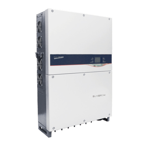
2 Product Introduction User Manual 2.2 Product Description 2.2.1 Product Appearance Fig. 2-2 Product Components Description *Image shown here is for reference only. Actual product you receive may differ. Item Name Description Inverter operation data viewing and parameters LCD display panel configuration can be performed via the LCD display panel. -
Page 17: Dimensions Of Inverter
User Manual 2 Product Introduction 2.2.2 Dimensions of Inverter Fig. 2-3 Outline Dimensions of Inverter (unit: mm) 2.2.3 LCD Display Panel As a human-computer interaction interface, LCD display panel comprises LED indicators, buttons and LCD display screen on the front panel of the inverter. ... -
Page 18: Dc Switch
2.3.1 Principle Description PV strings input voltage is transmitted to DC BUS via Boost circuit. The SG50KTL-M-20 is equipped with MPPTs for four DC inputs to ensure that the maximum power can be utilized even in different PV modules installation conditions. -
Page 19: Functions Description
User Manual 2 Product Introduction Fig. 2-5 Main Circuit Diagram of SG50KTL-M-20 2.3.2 Functions Description Inverter functions can be grouped as the following: Conversion function Inverter converts the direct current power into alternating current power, which conforms to the grid requirement of its installation country. -
Page 20: Derating
2 Product Introduction User Manual − Residual current protection − DC component of AC output current surveillance − Anti-islanding phenomena protection − Ambient temperature surveillance − DC over-voltage protection − Over current protection − Power module over-temperature protection 2.3.3 Derating Derating the output power is a way to protect the inverter from overload and potential faults. - Page 21 User Manual 2 Product Introduction Lower limit of the over-temperature derating: 60% of the nominal power. If the modules temperature and the inner temperature are both exceed the limit, the actual derating power value will be the less one. Grid Under-voltage Derating Once the grid voltage is in the defined range of Vgrid(Vmin…215V), the inverter will decrease the power output.
-
Page 22: 3 Installation Flow
3 Installation Flow Fig. 3-1 shows the installation flow of inverter. Please follow these procedures when installing the inverter. Fig. 3-1 Installation Flow Chart... - Page 23 User Manual 3 Installation Flow Tab. 3-1 Description of Installation Flow Order Description Reference Chapter Unpacking and inspection Section 4.1 Read this manual, especially the section on “safety Chapter 1 instruction” Store the inverter unit if not install immediately Section 4.4 Choose the best installation site Section 5.1 Moving the inverter to installation site...
-
Page 24: 4 Unpacking And Storage
4 Unpacking and Storage 4.1 Unpacking and Inspection The unit is thoroughly tested and strictly inspected before delivery. Damage may still occur during shipping. Check the packing for any visible damage upon receiving. Check the inner contents for damage after unpacking. ... -
Page 25: Identifying Inverter
Sungrow. Fig. 4-2 Nameplate of Inverters *Image shown here is for reference only. Actual product you receive may differ. -
Page 26: Delivery Contents
Store the inverter properly when the inverter is not to be installed immediately. Sungrow shall hold no liability for the corrosion of the device or the failure of device internal components caused by storage of the device not following the requirements specified in this manual. - Page 27 Replace the packing in time if necessary. The packing should be upright. If the inverter is stored for half a year or longer time, local installer or service dept. of Sungrow should perform a comprehensive test before connecting the inverter into PV power system.
-
Page 28: 5 Installing Inverter Onto Wall
5 Installing Inverter onto Wall 5.1 Selecting Installation Location Selecting an optimal installation location for the inverter is decisive for its operating safety as well as its expected efficiency and service life. Take the load capacity of the wall into account. The wall (such as concrete wall and metal structure) should be strong enough to hold the weight of the inverter over a long period of time. - Page 29 User Manual 5 Installing Inverter onto Wall Install the unit at eye level for easily buttons operation and display read. Never install the inverter horizontally, nor with a forward tilt, nor with a backward tilt nor even with upside down. ...
-
Page 30: Moving Inverter To Installation Site
5 Installing Inverter onto Wall User Manual Take enough space for convection into consideration during installing multiple inverters. It is suggested that position the multiple inverters in a staggered way if necessary. Do not install the inverter in a closed cabinet. Otherwise, the inverter will not operate normally. -
Page 31: Installing The Inverter
User Manual 5 Installing Inverter onto Wall Always remember the weight of the inverters. Grasp the equipment handles by both hands by means of handles. Move the unit with the help of others or the lifting device. ... - Page 32 5 Installing Inverter onto Wall User Manual Choose the best installation site according to above requirements. Place the Step 2 backplate onto the chosen metal frame and adjust it until it is in a horizontal position. Mark the positions to drill holes by using the backplate as the template. Step 3 Drill 6 holes at the marks you have made.
-
Page 33: Installing On Concrete Wall
User Manual 5 Installing Inverter onto Wall After fit the inverter to the backplate, fasten the inverter to the backplate Step 7 with two M4×16 screws. 5.3.2 Installing on Concrete Wall Remove backplate and fasteners from the packaging. Step 1 Place the backplate onto the chosen concrete wall and adjust it until it is in a Step 2 horizontal position. - Page 34 5 Installing Inverter onto Wall User Manual • If the installation location is lower, the inverter can be directly linked to the backplate, please follow step 6 and then jump to Step 10. • If the installation location is higher, the inverter can not be directly linked to the backplate, please perform steps 7 to 10.
- Page 35 User Manual 5 Installing Inverter onto Wall M12-screwed lifting ring is a standard component. It is not within the scope of delivery. Please purchase from the market if needed. Lead the rope (with sufficient load-carrying capacity) prepared beforehand Step 8 through the two lifting rings to lift the inverter.
-
Page 36: 6 Electrical Connection
6 Electrical Connection Once the inverter is firmly attached to the appropriate location, it can be connected to the PV power system. Installation shall comply with local regulations and technical rules. Installation shall comply with the relevant instructions of AS 4777.1. All electrical connection should follow the National Wiring Rules of Standard AS/NZS 3000. - Page 37 User Manual 6 Electrical Connection Fig. 6-1 Connection Cabinet Description *Image shown here is for reference only. Actual product you receive may differ. Description Description DC switch Waterproof air valve Plinth of DC SPDs (Surge Protection PV input terminals Devices) Configuration circuit board Communication cable glands AC connection terminal block...
-
Page 38: Connecting Inverter To Ac Grid
If several inverters are operated in parallel connection to grid, different requirements should be obeyed. Scenario 1: Several inverters are operated in parallel connection to the three-phase Low Voltage grid. Requirements: If the number of the grid-connected inverters exceed 40, please contact Sungrow. -
Page 39: Grid Connection
Voltage Grid. Requirements: If the number of the grid-connected inverters exceed 40, please contact Sungrow. The rate voltage on the low-voltage side of transformer must meet the inverter output electrical specification. A neutral point is necessary and must lead outwards as neutral conductor. - Page 40 6 Electrical Connection User Manual Voltage drop and other consideration may use the larger size cables. Avoid power loss in cables of more than 1% of nominal inverter rating. Withstand ambient temperature; Layout type (inside wall, underground, free air etc.); ...
- Page 41 User Manual 6 Electrical Connection Description Remark Accepted cable external diameter ranges from Protective layer 25~30.5 mm. Length of insulation to be 24 mm stripped off Insulation layer Range: 25-70mm ; recommended value: 50 Cross section of AC cables * The external diameter of the AC cable described in A is proper range. If you select AC cable with the external diameter within the range of 30.5~40 mm, before cable connection, please replace the original AC cable protection by the larger AC cable protection within the delivery.
-
Page 42: Connecting Inverter To Pv Arrays
PV array to the inverter. 6.3.1 PV Inputs Configuration The SG50KTL-M-20 inverter has four PV input areas DC1 input、 DC2 input、 DC3 input and 、DC4 input, each with its MPP tracker. There is a risk of inverter damage! The following requirements should be met;... - Page 43 User Manual 6 Electrical Connection The four PV inputs work independently, each with its own MPPT. Therefore the four PV inputs can be different with each other, including different PV module types, different numbers of connected in PV string, different tilt angles or orientation angle of PV modules.
-
Page 44: Pv Connection Procedures
6.3.2 PV Connection Procedures DC cables from PV strings should be equipped with DC connectors. Sungrow provides corresponding plug connectors in the scope of delivery for quick connection of PV inputs. Pairs of MC4 DC connectors are supplied in the scope of delivery. - Page 45 User Manual 6 Electrical Connection DC Cable Connection Make sure that all the DC and AC cables to the inverter are not live before you start the electrical work. Strip off 7mm insulation layer from Step 1 all DC cables. Assemble cable ends with crimp Step 2 contacts by crimping pliers.
- Page 46 6 Electrical Connection User Manual Disconnect the DC switch. Step 7 Check the connection cable of PV string for the correct polarity and that the Step 8 open-circuit voltage does not exceed the inverter input limit 1000V, even under the lowest operating temperature. •...
-
Page 47: Grounding The Inverter
User Manual 6 Electrical Connection Connect other PV strings following the above-mentioned procedures. Step 10 Seal the unused DC terminals with the waterproof plugs. Step 11 6.4 Grounding the Inverter Because of the transformer-less design of the inverter, neither the DC positive pole nor the DC negative pole of the PV string is permitted to be grounded. -
Page 48: Second Protective Earth Terminal
6 Electrical Connection User Manual Fig. 6-2 Grounding for Inverter 6.4.2 Second Protective Earth Terminal Position of Second PE Terminals There is a second PE terminal on one side of the inverter and it should be grounded. Fig. 6-3 Second PE terminal... -
Page 49: Communication Connection
The ground connection of this second PE terminal cannot replace the connection of the PE terminal of the AC cables. Make sure the two PE terminals are all grounded reliably. Sungrow shall hold no liability for any possible consequences caused by ignorance of this warning. -
Page 50: Communication System
6 Electrical Connection User Manual Before communication connection, prepare communication cable and RJ45 plug. RS485 cable’s requirements to ensure quality of communication: RS485 shielded twisted pair cables Shielded network cable A converter such as RS485-232 converter or SolarInfo Logger, which converts 485 to 232 signal, is needed between inverter and PC. - Page 51 User Manual 6 Electrical Connection Communication Connection Terminating (RS 485 A/B bus or RJ 45) Inverter Resistor RS 485 A/B bus RJ 45 Only out. Only out. Single one For Multiple Inverters Where there is more than one inverter, all inverters can be communicated in a daisy chain through RS485 communication cable.
- Page 52 6 Electrical Connection User Manual Communication connection (RS485 bus connection or Terminating Resistor RS485-RJ45 connection) erter RS485 n>15 RJ45 n≤15 Only out Only out Inverter In and Out In and Out Inverter 2~n-1 In and Out In and Out Inverter...
-
Page 53: Rs485 Communication Connection
User Manual 6 Electrical Connection 6.5.3 RS485 Communication Connection RS485A/B Bus Connection Lead the RS485 shielded twisted pair cables through the communication Step 1 cable gland to the configuration circuit board. Trip off the insulating layer of the communication cables for approximately 7 Step 2 mm. - Page 54 6 Electrical Connection User Manual SolarInfo logger and RS485-232 converter are optional parts and can be ordered from Sungrow. RJ45 Connection Lead Network cable through communication cable gland to the Step 1 configuration circuit board. Use the Ethernet crimper to crimp the cables and connect cables to RJ45 Step 2 plug according to TIA/EIA 568B.
-
Page 55: Ethernet Connection
See “10.12 Communication Parameters Setting”. SolarInfo logger and RS485-232 converter are optional parts and can be ordered from Sungrow. 6.5.4 Ethernet Connection Connect the inverter to PC through network ports to set up Ethernet communication. - Page 56 6 Electrical Connection User Manual Fig. 6-8 Multiple inverters network connection in daisy chain topology The network communication of the daisy chain is done via the inverter in-built switching chip. Therefore, when the inverter is damaged, the switching chip cannot work normally and the daisy chain communication will be interrupted.
- Page 57 User Manual 6 Electrical Connection Ethernet Connection Procedure Lead Network cable through communication cable gland to the Step 1 configuration circuit board. Use the Ethernet crimper to crimp the cables and connect cables to RJ45 Step 2 plug according to TIA/EIA 568B. Connect the RJ45 plug into the NET in/NET out terminal on the configuration Step 3 circuit board.
-
Page 58: 7 Commissioning
Suppose there are sufficient sunlight and Step 3 enough DC power. PV arrays initialize and supply DC power to inverter. The LCD display is activated to check the validity first. If there is a defect on the display, contact Sungrow. - Page 59 User Manual 7 Commissioning Press to choose country code. Confirm the Step 4 settings by Pressing ENTER Select the country code according to the Step 5 inverter’s installation country. Each country code represents corresponding local protective parameters that have been preset before delivery.
- Page 60 7 Commissioning User Manual If the country code set as DE, a Grid codes page as shown in the right will appear, where signifying low-voltage grid; MV signifying medium-voltage grid. Press to select grid code and press to confirm. ENTER If the country code set as TK, a Grid codes page as shown in the...
- Page 61 User Manual 7 Commissioning Set the inverter time as per local Step 9 time. Incorrect time setting will affect the data logging. Press move the cursor and Press to set the specific time and date. press to confirm setting. ENTER After configuring...
-
Page 62: 8 Disconnecting, Dismantling And Disposing The Inverter
8 Disconnecting, Dismantling and Disposing the Inverter 8.1 Disconnecting the Inverter For maintenance work or any service work, inverter must be switched off. In normal operation, switching off is not necessary. In order to disconnect the inverter from the AC and DC power sources, you should proceed as follows. -
Page 63: Dismantling The Inverter
User Manual 8 Disconnecting, Dismantling and Disposing the Inverter 8.2 Dismantling the Inverter Refer to Chapter 5 and Chapter 6 to dismantle the inverter in reverse steps. If the inverter will be reinstalled in the future, please refer to 4.4 Storage of Inverter for a proper conservation. -
Page 64: 9 Troubleshooting And Maintenance
4. Check whether DC input voltage exceeds the inverter start voltage of inverter. 5. If all above conditions are OK, please contact with Sungrow. 1. A fault is not removed yet. “Fault” indicator 2. Perform troubleshooting in according to fault type in LCD is lit screen. - Page 65 1. Check whether AC circuit breaker is triggered. 2. Check whether AC cables are all firmly connected. Islanding 3. Check whether grid is not in service. 4. If all conditions are OK and this fault still occurs in the LCD screen, contact Sungrow Service Dept..
- Page 66 Grid abnormal solution. detected 3. If the grid frequency is within the permissible range, contact Sungrow Service Dept.. The average grid voltage 1. Wait a moment for inverter recovery. exceeds the permissible 2. If the fault occurs repeatedly, contact...
- Page 67 Sungrow Service Dept.. 1. Wait a moment for inverter recovery. Sampling channel failure 2. If the fault occurs repeatedly, contact Sungrow Service Dept.. If the fault occurs repeatedly, contact Sungrow Current imbalance. Service Dept.. Disconnect and stop the inverter. Wait for ambient ambient temperature to rise above -25 ℃...
- Page 68 It is necessary to replace the DC SPD. Contact Fault with DC SPD Sungrow Service Dept.. Disconnect the inverter and replace the fuses. Fuse has blown out Contact Sungrow Service Dept.. fault occurred internal Communication fault of communication of the inverter. However, the inverter continues feeding into the grid.
-
Page 69: Maintenance
Devices Replace the fuse. Every 6 months check Contact Sungrow to order new DC SPDs. 9.2.2 Maintenance Instruction Fans’ Maintenance There are four fans at the side of the inverter for active cooling during running operation. If the fans are dirty or out of work, the inverter may not be well cooled down and its efficiency may accordingly decrease. - Page 70 9 Troubleshooting and Maintenance User Manual Disconnect the inverter from the grid first and then PV arrays before any maintenance work. Lethal voltage still exists in the inverter. Please wait for at least ten minutes and then perform maintenance work. ...
- Page 71 User Manual 9 Troubleshooting and Maintenance Release locking part four Step 9 connectors by pressing on the ribbing of the locking hooks and pull outwards. Remove fans from the inverter. Step 10 You can clean the dirty fans with soft brush or vacuum cleaner. Or Step 11 replace the broken fans.
-
Page 72: Contact Sungrow Service
A non-conductive fuse indicates a fault in the affected string. Check the affected string by installer of the PV generator and replace the Step 6 defective string fuse with same specification (order from Sungrow). Remove the blown string fuse. Step 7 Insert the new fuse into the fuse holder. -
Page 73: 10 Operation Of Lcd Display
10 Operation of LCD Display 10.1 Description of Button Function Inverter offers two buttons for user to look up the running information and configure parameters. The two buttons have multiple functions. Please refer to Tab. 10-1 before any operation onto inverter. Tab. -
Page 74: Inverter Menu Structure
10 Operation of LCD Display User Manual 10.2 Inverter Menu Structure Fig. 10-1 Menu Tree-English... -
Page 75: Main Screen
User Manual 10 Operation of LCD Display 10.3 Main Screen Once the inverter commissioning is finished, LCD display will enter the main screen as shown in Fig. 10-2. Fig. 10-2 Main screen Tab. 10-2 Description of the main screen State Description After being energized, inverter tracks the PV arrays’... -
Page 76: Adjust Contrast
10 Operation of LCD Display User Manual Tab. 10-3 Icon Description Icon Description Inverter is in IAP update process. Inverter in power derating state. Fans inside are working. Inverter is operating in warning state. 10.4 Adjust Contrast Press to enter into the contrast adjustment screen. Step 1 ... - Page 77 User Manual 10 Operation of LCD Display Main Screen (Press ENTER)→Menu→Run-inform (Press ENTER) LCD display will show the detailed running information. Scroll pages by pressing /. DC power input: the total PV input power. Vdc[V]: DC voltage of each input. Idc[A]: DC current of each input.
-
Page 78: Checking History Information
10 Operation of LCD Display User Manual 10.6 Checking History Information 10.6.1 Checking Running Records Main Screen (Press ENTER)→Menu (Press , Press ENTER)→His-inform (Press ×2, Press ENTER)→Run-record (Press ENTER) On the “Run-record” interface, scroll pages by pressing, and press to select the date you want to view. -
Page 79: Checking History Event Records
User Manual 10 Operation of LCD Display The inverter can only store at most 100 latest fault records. 10.6.3 Checking History Event Records Main Screen (Press ENTER)→Menu (Press , Press ENTER)→His-inform(Press , Press ENTER)→His-event (Press ENTER) On the “Evt-record” interface, scroll pages ... -
Page 80: Starting/Stopping
10 Operation of LCD Display User Manual Daily energy histogram: shows the power output every day in the present month. Press to view the daily energy of the latest 12 months. Monthly energy histogram: shows the power ... -
Page 81: Password Entry
User Manual 10 Operation of LCD Display 10.8 Password Entry Parameter setting is password-protected. To set the parameters, you should enter the correct password. Press ENTER to enter the Menu screen. Step 1 Press to move the cursor to “Set-param” item and confirm by pressing Step 2 ENTER A password confirmation screen will occur. -
Page 82: Time Setting
Please contact Sungrow if there is still time deviation after calibration. 10.9.3 Total Energy Deviation Adjustment If the accumulative value “E-total” in the inverter is different from the value in the external metering device, you should adjust energy by “Energy-adj”... -
Page 83: Load Default
User Manual 10 Operation of LCD Display Press to move the cursor and press to change value. Press ENTER confirm setting. The positive symbol “+” can be changed to the negative symbol “-”. The adjustment range is from -9999 to +9999 kWh. -
Page 84: Running Parameter Setting
10 Operation of LCD Display User Manual 10.10 Running Parameter Setting 10.10.1 Main Screen of Run-param ×3)→Set-param (Press ENTER)→Enter Main Screen (Press ENTER)→Menu (Press password (Press ENTER, Press )→Run-param (Press ENTER) On the “Run-param” screen, press to select one item and press ENTER to enter the setting interface. -
Page 85: Active/Reactive Power Parameters
User Manual 10 Operation of LCD Display Parameter Description Default Range -1.000~-0.80 Inverter output power +1.000 factor +0.800~+1.0 Inverter reactive power 0~+100%/ Q-Var limits 0.0% limitation 0~-100% Time from inverter Standby time 20~255s standby to startup Time param Time from inverter fault Recover time 0-900s is removed to standby... -
Page 86: Reactive Power Regulation
10 Operation of LCD Display User Manual P-Q Param P-W limits 100.0% Rate limit [ON/OFF] Power raise 100%/min Power decline 6000%/min Fault slowup [ON/OFF] Slowup rate 10%/min 10.10.3 Reactive Power Regulation Inverter provides reactive power regulation function. Use the “Q-Var switch” parameter to activate this function and select proper regulation mode. - Page 87 User Manual 10 Operation of LCD Display “Q(P)” Mode(when the country selection is not “IT”) PF changes with the inverter output power. If the country selection is not “IT” (Italy), after selecting Q(P) Mode, Press to enter the Run-param-Q(P) submenu. ...
- Page 88 10 Operation of LCD Display User Manual “Q(U)” Mode(when the country selection is not “IT”) The reactive power ratio changes with the grid voltage. If the country selection is not “IT” (Italy), after selecting Q(U) mode, Press to enter the Run-param-Q(U) submenu.
-
Page 89: Reactive Power Setting For Italy
User Manual 10 Operation of LCD Display Fig. 10-4 Reactive Power Regulation Curve in Q(U) Mode 10.10.4 Reactive Power Setting for Italy If the “Countries” selected is “IT” (Italy), several LCD menus and operation methods are different from other countries. The differences focus on “Run-param”... - Page 90 10 Operation of LCD Display User Manual Parameter Explanation Default Range Step Enter Q(P) regulation mode Uin** when grid voltage is above 105% 100~110% Exit from Q(P) Uout** regulation mode when grid 100% 90~100% voltage is below Uout *PA < PB≤ PC ** Uin>Uout Fig.
-
Page 91: Save P/Q-Set
User Manual 10 Operation of LCD Display Parameter Explanation Default Range Step V1i* Grid voltage at point C (in %) 90~110% V2s* Grid voltage at point A (in %) 108% 90~110% V1s* Grid voltage at point B (in %) 110% 90~110% The max. -
Page 92: Lvrt Parameter
10 Operation of LCD Display User Manual 10.10.7 LVRT Parameter ×3)→Set-param(Press ENTER)→ Main Screen (Press ENTER )→Menu (Press Enter password (Press ENTER, Press )→Run-param (Press Press ×2)→ ENTER, LVRT param (Press ENTER) 10.10.8 Derating Parameters ×3)→Set-param(Press ENTER)→ Main Screen (Press ENTER )→Menu (Press Enter password (Press ENTER, Press )→Run-param (Press... -
Page 93: Protection Parameter Setting
User can only check the parameter in this interface. The default values of the protection parameters have been preset as per grid code of corresponding countries. To set the protection parameter, please contact Sungrow to acquire advanced password. 10.11.1 Country Setting... - Page 94 10 Operation of LCD Display User Manual Country Code Country Language Belgium French Denmark English Greece English Netherlands English Portugal English China Chinese Sweden English Romania English Thailand English Turkey English Other Country not mentioned above English When the country selected is TH, TK, DE, GR or Other, the grid code specific to them ...
-
Page 95: Single-Stage Protection Parameter Setting
User Manual 10 Operation of LCD Display 10.11.2 Single-stage Protection Parameter Setting following interfaces will appear Single-stage is selected. Press to select parameter, Press to move cursor and Press to set the appropriate value. Confirm settings by Pressing ENTER. 10.11.3 Multi-stage Protection Parameter Setting The following interfaces will appear if Multi-stage is selected. -
Page 96: Protection Recovery Setting
10 Operation of LCD Display User Manual Parameter Explanation Ⅱ-Max-F. time Stage Ⅱ Grid over-frequency (f>>) tripping time Min-F. prot Under-frequency protection Ⅰ-Min-F. grid Stage ⅠGrid under-frequency (f<) Ⅰ-Min -F. time Stage Ⅰ Grid under-frequency (f<) tripping time Ⅱ-Min -F. grid Stage Ⅱ... -
Page 97: Communication Parameter Setting
User Manual 10 Operation of LCD Display 10.12 Communication Parameter Setting ×3)→Set-param (Press ENTER)→Enter Main Screen (Press ENTER)→Menu (Press password (Press ENTER, Press ×3)→Com-param (Press ENTER) Press to move cursor and press to set the appropriate value. Confirm settings by Pressing ENTER. -
Page 98: 11 Appendix
11 Appendix 11.1 Technical Data Parameters SG50KTL-M-20 Input Side Data Max. PV input power 52000W Max. PV input voltage 1000V Startup voltage 300V Nominal input voltage 590V MPP voltage range 300…850V MPP voltage range for nominal power 500...850V No. of MPPT(s) Max. -
Page 99: Exclusion Of Liability
Parameters SG50KTL-M-20 Leakage current protection DC switch Integrated Overvoltage protection Type II DIN rail surge arrester System data Max. efficiency 98.9% Max. European efficiency 98.5% Stand-by power Isolation method Transformerless Ingress protection rating IP65 Night power consumption <1W Operating ambient temperature range -25...+60℃... -
Page 100: About Us
The power rating of Sungrow products covers from hundred watt to mega-watt systems. The vision of Sungrow is to help our customers acquire stable and clean power with minimum cost, maximum reliability and enhanced safety. -
Page 101: Contact Information
Contact Information Should you have any question about this product, please contact us. Company: Sungrow Power Supply Co., Ltd. Website: www.sungrowpower.com Email: info@sungrow.cn, service@sungrow.cn No.1699 Xiyou Rd., New & High Technology Industrial Development Address: Zone, Hefei, P. R. China. Zip:... - Page 102 Sungrow Power Supply Co., Ltd. Add: No.1699 Xiyou Rd.,New & High Technology Industrial Development Zone, 230088,Hefei, P. R. China. Post Zip: 230088 Web: www.sungrowpower.com Tel: +86 551 6532 7834/6532 7845 E-mail: info@sungrow.cn Fax: +86 551 6532 7856 Specifications are subject to changes without advance notice.
Need help?
Do you have a question about the SG50KTL-M-20 and is the answer not in the manual?
Questions and answers