
Related Manuals for Tractel Dynarope HF 36 Series


Summary of Contents for Tractel Dynarope HF 36 Series
- Page 1 29 RUE DU Progrès - 93107 MONTREUIL CEDEX - France Tél. (1) 48.58.91.32 - Télex TRACTEL 230 020 - Adresse télégraphique TRACTELEV Montreuil - Télécopie (1) 48.58.19.95 Dynarope HF 36/. Operation and Maintenance Manual Révision 09...
- Page 2 9. Tractel declines any responsibility for use of this unit in a setup configuration not described in this manual.
-
Page 3: Table Of Contents
dynarope SUMMARY 1. Brochure 2. Introduction Pages • General remarks • Pictures 1 , 2 • loadcells • Display HF 87/T • Standard Mode • Special Mode • Data bank • Specific calibration • Calibration in Special Mode • Display HF 87 / A •... -
Page 4: General Remarks
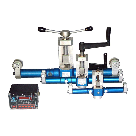
GENERAL REMARKS. The HF 36 Dynarope allows the load in a tensioned wire rope to be measured without having to dismantle it. The device includes an HF 36 strain gauges sensor and a digital display unit. An analogue display units is available as an option and can be used under specific repetitive conditions. The accessories are: Lemo connection lead , battery charger, various leather protection boxes, RS 232 connection lead and a recuperation data’s software. -
Page 5: Loadcells
COMPONENTS 1. Crank 2. Bronze nut 3. Threaded rod 4. Crank support 5. Pusher Spool pin Spool Spool support Strain gauges 10 . Lemo plug 11. Frequency converter 12. Stop block (rotary on /2 & /3) 1. LED Display 2. Red dot * 3. -
Page 6: Standard Mode
THE SENSORS Three standards models are available. • HF 36 / 0 for wire ropes from 3 to 8 mm diameter. Maximum capacity : 1.500 daN • HF 36 / 1 for wire ropes from 4 to 13 mm diameter. Maximum capacity : 5.000 daN •... -
Page 7: Specific Calibration
THE DATA BANK. General information. The data bank was generated using measurements made on a tensile test bench. For each wire rope diameter stored in the memory, 5 similar wire ropes, but from different origin were selected amongst the widely sold wire ropes on the market. Each stored measurement is the average of these measurements made following a 120°... -
Page 8: Calibration In Special Mode
CUSTOM CALIBRATION IN SPECIAL MODE This process (made by the customer) allows to correct the “raw” signal provided by the sensor for a given wire rope at a given strain. Contrary to a specific calibration made by the factory that gives a correction with a formula. - Page 9 HF 87/A DISPLAY UNITS This model is an analogue display unit which converts the tension signal generated by the strain into a corresponding value expressed in daN . This display can be calibrated by the factory our on customer’s request. A correction abacus is worked out on the basis of the wire rope specification and the load to be checked.
-
Page 10: Correction Abacus
CORRECTION ABACUS Example : Typical abacus delivered with an analogue HF 87/A and its sensor. Calibration at 550 daN. Wire rope 9,2 mm (19 x 1 ) Displayed value in daN CRANK TORQUE. There is no particular torque recommended to tighten up the crank onto the wire rope. It’s the wire rope angle that induce strain in the arms of the sensor. -
Page 11: Display Hf 87/A
Technical DYNAROPE : 2020 GB TENSIOMETER rev N° 7 Sheet HF 36 date : 04/03 page : 1/1 APPLICATION : This electronic load cell has been designed to measure the effort applied in a wire rope . The resulting signal is used in a digital monitor controlled by a microprocessor, which corrects the force information according to the wire rope specification. - Page 12 Technical DYNAROPE : 2024GB rev N° 3 DIGITAL DISPLAY Sheet HF 87/ T date : 04/03 page : 1/2 APPLICATIONS: The display corrects by calculation the information Controlled by microprocessor, this display box from the sensor taking in account the wire ropes has been designed to show after correction the diameter and specification.
- Page 13 Technical DYNAROPE : 2024GB rev N° 3 DIGITAL DISPLAY Sheet HF 87/ T date : 04/03 page : 2/2 SPECIFICATION OF THE HF 87/1/T DISPLAY: Two readout modes are available. 1. STANDARD MODE Definition : The standard display Mode uses a data base to correct the raw data from the sensor. This data base has been set up as a result of actual measurements taking into account the following factors : A) The wire rope diameter •...
- Page 14 Technical DYNAROPE : 2025GB rev N° 3 DIGITAL DISPLAY Sheet HF 87/A date : 04/03 page : 1/1 APPLICATIONS : This model is an analogue display unit which converts the tension signal generated by the strain a corresponding value expressed in daN . This display is calibrated in the factory on customer’s request. A correction abacus is worked out on the basis of the wire rope specification and the load to be checked.
-
Page 15: Hf 87/1/P
SYNOPTIC OF HF 87/1/P DISPLAY. USER MENU (see details page 14) Only for 36/2 /3 models Stan 10 > 22 POS 1 Stru Soft Switch ON 36 2 Da N rIGI Select the sensor model used. 1 > 200 SPEC N CAL CALI N CAL... -
Page 16: Hf 87/1/P
SYNOPTIC OF HF 87/1/P « ZERO » MENU Precondition : Sensor free of any load Press Press Tare & F1 during xxxx 4567 Da N COdE Da N) SCHIFT 3 seconds SYNOPCTIC OF HF 87/1/P RECORD MENU (see details page 15) Press arrow 1 >... -
Page 17: Standard Mode
STANDARD MODE INSTRUCTION FOR USE Essential conditions: • The load cell and the display should be correctly connected • Load cell fixed on taut or not taut wire rope • Turn the display ON Our example: Control of a steel multi-strand wire rope, ∅ 10 mm tightened 850 daN. DISPLAY ACTION EXPLANATION... -
Page 18: Record Instruction
RECORD INSTRUCTION (see synoptic page 13) Essential conditions: • Sensor fixed onto the wire rope , end of a control operation . DISPLAY ACTION EXPLANATION Readout (in daN) 6 5 0 6 5 0 Press rE F Press E 1 à 200 With the arrows, select the operation reference number Valid with E GrAd... -
Page 19: Special Mode
SPECIAL MODE CALIBRATION INSTRUCTION Essential conditions : • Load cell and display should be correctly connected • Load cell fixed on taut or not taut wire rope • For HF 36/2 & /3, the rotating stop block must be adjusted according with the wire rope diameter ( Position must be similar as in the standard mode). - Page 20 SPECIAL MODE INSTRUCTION FOR USE Essential conditions : • Load cell and display should be correctly connected • Load cell fixed on taut or not taut wire rope • For HF 36/2 & /3, the rotating stop block must be adjusted according to the information given by the display.
-
Page 21: Abbreviation Explanation
Abbreviation explanation. Readout +/- 99 : Temperature from - 99°C to 99°C 0 to 99 : Wind speed. 1 to 200 : Memory number corresponding to a specific calibration (Used in calibration process) 1 to 360 : Wind Direction from 1° to 360° 200 - Full : Memory capacity 4 to 22... - Page 22 S t r u : Wire rope structure ( Normal , Rigid or Soft ) SpEd : Wind speed Switch ON : Turn display ON : Low battery Note :...
-
Page 23: Hf 36 / 1 Frequency
HF 36 / 1,2,3 Frequency 100% CAPTEUR H F 8 7 / P/ 1 POWER RS232 On/Off Shift T are SOFT HF 36 N° Description code Digital kit HF 36/1 29808 Digital kit HF 36/2 29818 Digital kit HF 36/3 36008 Loadcell HF 36/1 55268... -
Page 24: Hf 36 / 1 Analogue
HF 36 / 1 ,2 Analogue N° Description code Analogue kit HF 36/1 29788 Analogue kit HF 36/2 29798 Loadcell HF 36/1 45988 Leather protection 1 55308 Loadcell HF 36/2 55228 Leather protection 2 55318 Digital display HF 87/A 55288 Leather box 49358 Lemo 4 poles...
Need help?
Do you have a question about the Dynarope HF 36 Series and is the answer not in the manual?
Questions and answers