Table of Contents

Subscribe to Our Youtube Channel
Related Manuals for Aaeon TKS-G20-LN05


Summary of Contents for Aaeon TKS-G20-LN05
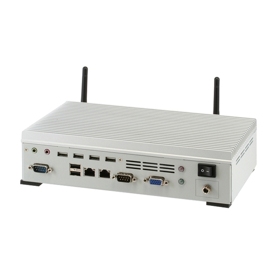
- Page 1 E m b e d d e d C o n t r o l l e r T K S - G 2 0 - L N 0 5 TKS-G20-LN05 Compact Embedded Controller ® Intel Atom™ D510 1.66GHz Processor Dual LAN, 2/6 USB2.0, 2/6 COM, 1 VGA 2 PCI-Express Mini Card TKS-G20-LN05 Manual 1 May 2011...
- Page 2 AAEON assumes no liabilities resulting from errors or omissions in this document, or from the use of the information contained herein. AAEON reserves the right to make changes in the product design without notice to its users.
- Page 3 E m b e d d e d C o n t r o l l e r T K S - G 2 0 - L N 0 5 Acknowledgments All other products’ name or trademarks are properties of their respective owners.
- Page 4 Before you begin operating your PC, please make sure that the following materials are enclosed: TKS-G20-LN05 Embedded Controller CD-ROM for manual (in PDF format) and drivers If any of these items should be missing or damaged, please contact...
- Page 5 E m b e d d e d C o n t r o l l e r T K S - G 2 0 - L N 0 5 Safety & Warranty 1. Read these safety instructions carefully. 2. Keep this user's manual for later reference. 3.
- Page 6 E m b e d d e d C o n t r o l l e r T K S - G 2 0 - L N 0 5 The equipment does not work well, or you cannot get it to work according to the user’s manual.
- Page 7 E m b e d d e d C o n t r o l l e r T K S - G 2 0 - L N 0 5 Below Table for China RoHS Requirements 产品中有毒有害物质或元素名称及含量 AAEON Boxer/ Industrial System 有毒有害物质或元素 部件名称 铅...
-
Page 8: Table Of Contents
1.1 Introduction..............1-2 1.2 Features ..............1-3 1.3 Specifications ............1-4 Chapter 2 Hardware Installation 2.1 Dimension and I/O of TKS-G20-LN05....... 2-2 2.2 Location of Connectors and Jumpers of the Main Board ..................2-3 2.3 List of Jumpers ............2-5 2.4 List of Connectors ............. -
Page 9: A.1 Programming
E m b e d d e d C o n t r o l l e r T K S - G 2 0 - L N 0 5 Appendix A Programming The Watchdog Timer A.1 Programming ............A-2 A.2 W83627DHG Watchdog Timer Initial Program ..A-7 Appendix B DIO B.1 DIO ...............B-2 viii... -
Page 10: Chapter 1 General Information
E m b e d d e d C o n t r o l l e r T K S - G 2 0 - L N 0 5 Chapter General Information 1- 1 Chapter 1 General Information... -
Page 11: Introduction
System integrators will need a multifunction device to satisfy commercial needs for such public advertising. The TKS-G20-LN05 is designed for indoor environments due to the following reasons; first, the TKS-G20-LN05 offers low power consumption system that while operating in ambient temperatures ranging from 0°... -
Page 12: Features
E m b e d d e d C o n t r o l l e r T K S - G 2 0 - L N 0 5 1.2 Features ® Intel Atom D510 1.66 GHz Processor Intel ICH8M Chipse USB2.0 x 6, COM x 6, Compact Flash™... -
Page 13: Specifications
E m b e d d e d C o n t r o l l e r T K S - G 2 0 - L N 0 5 1.3 Specifications System ® Intel Atom D510 1.66 GHz Processor Memory DDR2 533/667 SODIMM x 1, Max. - Page 14 E m b e d d e d C o n t r o l l e r T K S - G 2 0 - L N 0 5 Mechanical and Environmental Construction Heavy Duty Steel Chassis Color White Mounting Wallmount Dimension...
- Page 15 E m b e d d e d C o n t r o l l e r T K S - G 2 0 - L N 0 5 Chapter Quick Installation Guide 2 - 1 Chapter 2 Quick Installation Guide...
-
Page 16: Dimension And I/O Of Tks-G20-Ln05
E m b e d d e d C o n t r o l l e r T K S - G 2 0 - L N 0 5 2.1 Dimension and I/O of TKS-G20-LN05 2 - 2 Chapter 2 Quick Installation Guide... -
Page 17: Location Of Connectors And Jumpers Of The Main Board
E m b e d d e d C o n t r o l l e r T K S - G 2 0 - L N 0 5 2.2 Location of Connectors and Jumpers of the Main Board Component Side 2 - 3 Chapter 2 Quick Installation Guide... - Page 18 E m b e d d e d C o n t r o l l e r T K S - G 2 0 - L N 0 5 Solder Side 2 - 4 Chapter 2 Quick Installation Guide...
-
Page 19: List Of Jumpers
E m b e d d e d C o n t r o l l e r T K S - G 2 0 - L N 0 5 2.3 List of Jumpers The board has a number of jumpers that allow you to configure your system to suit your application. -
Page 20: List Of Connectors
E m b e d d e d C o n t r o l l e r T K S - G 2 0 - L N 0 5 2.4 List of Connectors The board has a number of connectors that allow you to configure your system to suit your application. - Page 21 E m b e d d e d C o n t r o l l e r T K S - G 2 0 - L N 0 5 CN21 COM Port #3 CN22 COM Port #2 CN23 Audio Line In/Out and MIC Connector CN24 RJ-45 Ethernet #2 CN25...
-
Page 22: Com2 Rs-232/422/485 Selection (Cn22)
E m b e d d e d C o n t r o l l e r T K S - G 2 0 - L N 0 5 2.5 COM2 RS-232/422/485 Selection (CN22) COM2 RS-232/422/485 selection for AAEON TKS series is set in BIOS setting as following: Entering BIOS Setting Menu: Choose "Integrated Peripherals... -
Page 23: Digital I/O Connector (Cn26)
E m b e d d e d C o n t r o l l e r T K S - G 2 0 - L N 0 5 RXD+ TXD+ RXD- N/C / +5 Volt. / (+12 Volt.) Ground RS-485 Mode Signal... - Page 24 E m b e d d e d C o n t r o l l e r T K S - G 2 0 - L N 0 5 Address(Register) BIOS Setting Connector F75111 GPIO Setting (I2C address) Definition Output Input Port 1 @6Eh...
-
Page 25: Hard Disk Installation
E m b e d d e d C o n t r o l l e r T K S - G 2 0 - L N 0 5 2.8 Hard Disk Installation Step 1: Unfasten the screws on the top of the heat-sink and you will see the inside of the system. - Page 26 E m b e d d e d C o n t r o l l e r T K S - G 2 0 - L N 0 5 Step 2: Unfasten the two screws on the front side and right side of the chassis.
- Page 27 E m b e d d e d C o n t r o l l e r T K S - G 2 0 - L N 0 5 Step 4: Connect the HDD cables Step 5: Fasten the two screws on the front side and right side of the chassis.
-
Page 28: Accessory Installation
E m b e d d e d C o n t r o l l e r T K S - G 2 0 - L N 0 5 Step 6: Fasten the screws on the top of the heatsink. 2.9 Accessory Installation Step 1: Unfasten the screws on the rear panel 2 - 14... - Page 29 E m b e d d e d C o n t r o l l e r T K S - G 2 0 - L N 0 5 Step 2: You can see the inside placement of RAM, CF card, PCIe slot for you installation.
-
Page 30: Wallmount Kit Installation
E m b e d d e d C o n t r o l l e r T K S - G 2 0 - L N 0 5 2.10 Wallmount Kit Installation Get the brackets ready and fasten appropriate four screws on each bracket. After fastening the two brackets on the bottom lid of, the wall mount kit installation has been finished. -
Page 31: Chapter 3 Ami Bios Setup
E m b e d d e d C o n t r o l l e r T K S - G 2 0 - L N 0 5 Chapter BIOS Setup Chapter 3 AMI BIOS Setup 3-1... -
Page 32: System Test And Initialization
3. The CMOS memory has lost power and the configuration information has been erased. The TKS-G20-LN05 CMOS memory has an integral lithium battery backup for data retention. However, you will need to replace the complete unit when it finally runs down. -
Page 33: Ami Bios Setup
E m b e d d e d C o n t r o l l e r T K S - G 2 0 - L N 0 5 3.2 AMI BIOS Setup AMI BIOS ROM has a built-in Setup program that allows users to modify the basic system configuration. -
Page 34: Chapter 4 Driver Installation
E m b e d d e d C o n t r o l l e r T K S - G 2 0 - L N 0 5 Chapter Driver Installation 4 - 1 Chapter 4 Driver Installation... - Page 35 E m b e d d e d C o n t r o l l e r T K S - G 2 0 - L N 0 5 The TKS-G20-LN05 comes with a CD-ROM that contains all drivers and utilities that meet your needs.
- Page 36 T K S - G 2 0 - L N 0 5 4.1 Installation: Insert the TKS-G20-LN05 CD-ROM into the CD-ROM Drive. And install the drivers from Step 1 to Step 5 in order. Step 1 – Install Chipset Driver 1.
- Page 37 E m b e d d e d C o n t r o l l e r T K S - G 2 0 - L N 0 5 Step 4 – Install Audio Driver 1. Click on the STEP4-AUDIO folder and select the OS folder your system is 2.
- Page 38 E m b e d d e d C o n t r o l l e r T K S - G 2 0 - L N 0 5 Appendix Programming the Watchdog Timer Appendix A Programming the Watchdog Timer...
- Page 39 TKS-G20-LN05 utilizes W83627DHG-P chipset as its watchdog timer controller. Below are the procedures to complete its configuration and the AAEON intial watchdog timer program is also attached based on which you can develop customized program to fit your application. Configuring Sequence Description...
- Page 40 E m b e d d e d C o n t r o l l e r T K S - G 2 0 - L N 0 5 (3) Exit the W83627DHG config Mode. Undesired result may occur if the config Mode is not exited normally. (1) Enter the W83627DHG config Mode To enter the W83627DHG config Mode, two special I/O write operations are to be performed during Wait for Key state.
- Page 41 E m b e d d e d C o n t r o l l e r T K S - G 2 0 - L N 0 5 = 010 Power LED pin is driven low. = 011 Power LED pin outputs 2Hz pulse with 50% duty cycle.
- Page 42 E m b e d d e d C o n t r o l l e r T K S - G 2 0 - L N 0 5 WatchDog Timer Register II (Index=F6h, Default=00h) Bit 7-0 = 0 x 00 Time-out Disable = 0 x 01 Time-out occurs after 1 second/minute = 0 x 02 Time-out occurs after 2...
- Page 43 E m b e d d e d C o n t r o l l e r T K S - G 2 0 - L N 0 5 Force Watchdog Timer time-out event: this bit is self-clearing Bit 4 : Watchdog Timer Status.
-
Page 44: A.2 W83627Dhg Watchdog Timer Initial Program
E m b e d d e d C o n t r o l l e r T K S - G 2 0 - L N 0 5 A.2 W83627DHG Watchdog Timer Initial Program Example: Setting 10 sec. as Watchdog timeout interval ;/////////////////////////////////////////////////////////////////////////////////////////////// Mov dx,2eh ;Enter W83627DHG config mode... - Page 45 E m b e d d e d C o n t r o l l e r T K S - G 2 0 - L N 0 5 ;/////////////////////////////////////////////////////////////////////////////////////////////// Dec dx Mov al,0f5h ;CRF5 (PLED mode register) Out dx,al Inc dx In al,dx And al,not 08h...
- Page 46 E m b e d d e d C o n t r o l l e r T K S - G 2 0 - L N 0 5 Appendix Appendix B DIO...
- Page 47 E m b e d d e d C o n t r o l l e r T K S - G 2 0 - L N 0 5 B.1 DIO The F75111 provides one serial access interface, I2C Bus, to read/write internal registers.
- Page 48 E m b e d d e d C o n t r o l l e r T K S - G 2 0 - L N 0 5 Name Description GP27_OCTRL VSB3V GPIO 27 output control. Set to 1 for output function.
- Page 49 E m b e d d e d C o n t r o l l e r T K S - G 2 0 - L N 0 5 Name Description GP27_PSTS VSB3V Read the GPIO27 data on the pin. GP26_PSTS VSB3V Read the GPIO26 data on the pin.
- Page 50 #define SMBUS_STATUS_INTR 0x02 //After read/write done #define SMBUS_STATUS_HOST_BUSY 0x01 // int main(void) int i,out_reg,in_reg,data_offset; int s_count; unsigned char s_data, w_data,f_data0,f_data1,f_data2,f_data3; printf("\n\t #*#================================================#*#\n"); printf("\t ||| AAEON DIO Test Program For 4_In+4_Out |||\n"); printf("\t #*#================================================#*#\n"); printf("\t "); out_reg=0x21; in_reg=0x22; //================Test_Pattern=0x0F=================== //Write GP20-27=0Fh SMBusWrite(smbase, dev_addr , out_reg, 0x0F);...
- Page 51 E m b e d d e d C o n t r o l l e r T K S - G 2 0 - L N 0 5 for(i=0;i<time;i++) outportb(0xeb,0xFF); return 0; int SMBusGetStatus(unsigned int SMBus_Base) //no error pending return inportb(SMBus_Base+SMBUS_REG_STATUS);...
- Page 52 E m b e d d e d C o n t r o l l e r T K S - G 2 0 - L N 0 5 status IO_Delay(1); if ((Temp & 0x02) == 1) //termination of command ? return 0;...
- Page 53 E m b e d d e d C o n t r o l l e r T K S - G 2 0 - L N 0 5 return -1; int SMBusRead(unsigned int SMBus_Base, int DeviceID, int REG_DATA_OFFSET) unsigned char read_data;...
- Page 54 E m b e d d e d C o n t r o l l e r T K S - G 2 0 - L N 0 5 status; SMBusCheckReady( SMBus_Base ); outportb(SMBus_Base+SMBUS_REG_DID_RW, DeviceID + SMBUS_DATA_WRITE); //ID cmd(Write) IO_Delay(1000);...
Need help?
Do you have a question about the TKS-G20-LN05 and is the answer not in the manual?
Questions and answers