Table of Contents
Advertisement
Quick Links
Advertisement
Table of Contents

Related Manuals for Aaeon BOXER-6614


Summary of Contents for Aaeon BOXER-6614
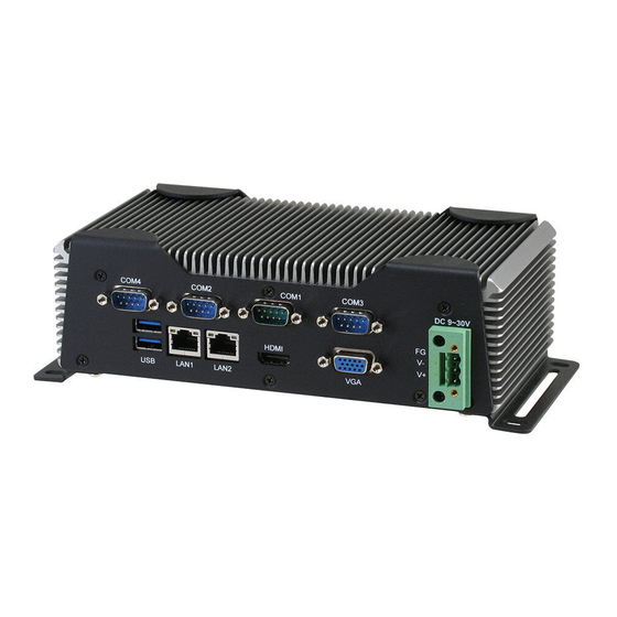
- Page 1 B O X E R - 6 6 1 4 BOXER-6614 Embedded Controller ® Intel Quad Core N2930 1.83GHz Processor Dual LAN, 3 USB2.0, 1 USB3.0, 4 COM 1 Full Size, 1 Half Size Mini Card BOXER-6614 Manual 1 December 24, 2014...
- Page 2 AAEON assumes no liabilities resulting from errors or omissions in this document, or from the use of the information contained herein. AAEON reserves the right to make changes in the product design without notice to its users.
- Page 3 E m b e d d e d C o n t r o l l e r B O X E R - 6 6 1 4 Acknowledgments All other products’ name or trademarks are properties of their respective owners. •...
- Page 4 E m b e d d e d C o n t r o l l e r B O X E R - 6 6 1 4 Packing List Before you begin operating your PC, please make sure that the following materials are enclosed: BOXER-6614 Embedded Controller Wallmount Brackets Screw Package ...
- Page 5 E m b e d d e d C o n t r o l l e r B O X E R - 6 6 1 4 Safety & Warranty 1. Read these safety instructions carefully. 2. Keep this user's manual for later reference. 3.
- Page 6 E m b e d d e d C o n t r o l l e r B O X E R - 6 6 1 4 The equipment does not work well, or you cannot get it to work according to the user’s manual. The equipment has been dropped and damaged.
- Page 7 E m b e d d e d C o n t r o l l e r B O X E R - 6 6 1 4 China RoHS Requirements 产品中有毒有害物质或元素名称及含量 AAEON Boxer/ Industrial System 有毒有害物质或元素 部件名称 铅 汞...
- Page 8 1.2 Features ..............1-3 1.3 Specifications ............1-4 Chapter 2 Hardware Installation 2.1 Dimension and I/O of BOXER-6614 ......2-2 2.2 Allocation of USB Ports ..........2-6 2.3 Connectors and Jumpers of the Main Board .... 2-7 2.4 List of Jumpers ............2-9 2.5 List of Connectors .............
- Page 9 E m b e d d e d C o n t r o l l e r B O X E R - 6 6 1 4 2.20 LPT Port (CN13) ............2-23 2.21 COM Port 3 Connector (CN14 of mainboard) ..2-24 2.22 COM Port 4 Connector (CN15 of mainboard) ..
- Page 10 E m b e d d e d C o n t r o l l e r B O X E R - 6 6 1 4 Chapter 3 AMI BIOS Setup 3.1 System Test and Initialization........3-2 3.2 AMI BIOS Setup ............
- Page 11 E m b e d d e d C o n t r o l l e r B O X E R - 6 6 1 4 Chapter General Information 1- 1 Chapter 1 General Information...
-
Page 12: Introduction
E m b e d d e d C o n t r o l l e r B O X E R - 6 6 1 4 1.1 Introduction AAEON introduces the newest product in the Boxer series, ® BOXER-6614, which utilizes the Intel Quad Core 1.83GHz SoC... -
Page 13: Features
VGA+HDMI Output, dual view/simultaneous display support SATA 3.0Gb/s Full size Mini Card with SIM slot x 1 Half size Mini Card x 1 (Factory install only) Fanless System Design AAEON’s Hi-Safe Support 1- 3 Chapter 1 General Information... -
Page 14: Specifications
E m b e d d e d C o n t r o l l e r B O X E R - 6 6 1 4 1.3 Specifications System ® Intel Quad Core 1.83GHz SoC N2930 Memory DDR3L 1333 SODIMM x 1, Max. - Page 15 E m b e d d e d C o n t r o l l e r B O X E R - 6 6 1 4 Mechanical and Environmental Construction Metal Fe. Color Dark Gray Mounting Desktop mount/ Wallmount/ Din Rail ...
-
Page 16: Installation
E m b e d d e d C o n t r o l l e r B O X E R - 6 6 1 4 Chapter Hardware Installation Chapter 2 Hardware Installation... -
Page 17: Dimension And I/O Of Boxer-6614
E m b e d d e d C o n t r o l l e r B O X E R - 6 6 1 4 2.1 Dimension and I/O of BOXER-6614 BOXER-6614-A1 2 - 2 Chapter 2 Hardware Installation... - Page 18 E m b e d d e d C o n t r o l l e r B O X E R - 6 6 1 4 BOXER-6614-A1M 2 - 3 Chapter 2 Hardware Installation...
- Page 19 E m b e d d e d C o n t r o l l e r B O X E R - 6 6 1 4 BOXER-6614-A2 2 - 4 Chapter 2 Hardware Installation...
- Page 20 E m b e d d e d C o n t r o l l e r B O X E R - 6 6 1 4 BOXER-6614-A2M 2 - 5 Chapter 2 Hardware Installation...
-
Page 21: Allocation Of Usb Ports
E m b e d d e d C o n t r o l l e r B O X E R - 6 6 1 4 2.2 Allocation of USB Ports Port 2(USB2.0 ) Port 3(USB2.0 ) USB 3.0 Port 0(USB3.0 ) Port 1(USB2.0 ) 2 - 6... -
Page 22: Connectors And Jumpers Of The Main Board
E m b e d d e d C o n t r o l l e r B O X E R - 6 6 1 4 2.3 Connectors and Jumpers of The Main Board Component Side 2 - 7 Chapter 2 Hardware Installation... - Page 23 E m b e d d e d C o n t r o l l e r B O X E R - 6 6 1 4 Solder Side 2 - 8 Chapter 2 Hardware Installation...
-
Page 24: List Of Jumpers
E m b e d d e d C o n t r o l l e r B O X E R - 6 6 1 4 2.4 List of Jumpers The board has a number of jumpers that allow you to configure your system to suit your application. -
Page 25: List Of Connectors
E m b e d d e d C o n t r o l l e r B O X E R - 6 6 1 4 2.5 List of Connectors The board has a number of connectors that allow you to configure your system to suit your application. - Page 26 E m b e d d e d C o n t r o l l e r B O X E R - 6 6 1 4 CN34 DDR3L SO-DIMM Slot CN35 UIM Card Socket CN37 Mini-Card Slot (Full-Mini Card) 2 - 11 Chapter 2 Hardware Installation...
-
Page 27: Setting Jumpers
E m b e d d e d C o n t r o l l e r B O X E R - 6 6 1 4 2.6 Setting Jumpers You configure your card to match the needs of your application by setting jumpers. -
Page 28: Com2 Pin8 Function Selection (Jp8)
E m b e d d e d C o n t r o l l e r B O X E R - 6 6 1 4 2.7 COM2 Pin8 Function Selection (JP8) +12V Ring(Default) Function +12V Ring(Default) 2.8 COM3 Pin8 Function Selection (JP9) +12V Ring(Default) Function... -
Page 29: Clear Cmos Jumper (Jp21)
E m b e d d e d C o n t r o l l e r B O X E R - 6 6 1 4 JP17 Function Disable Enable (Default) Note 1: Disable Auto Power Button JP17(1-2) : Need to use power button JP19(1-2) to power on the system. -
Page 30: V Output For Sata Hdd (Cn4)
E m b e d d e d C o n t r o l l e r B O X E R - 6 6 1 4 SMB_CLK +3.3V PS_ON# +3.3V +5VSB 2.12 +5V Output for SATA HDD (CN4) Pin Name Signal Type Signal Level... -
Page 31: Sata Port1 (Cn6)
E m b e d d e d C o n t r o l l e r B O X E R - 6 6 1 4 2.14 SATA Port1 (CN6) Pin 1 Pin 7 Pin Name Signal Type Signal Level SATA_TX+ DIFF... -
Page 32: Audio I/O Port (Cn9)
E m b e d d e d C o n t r o l l e r B O X E R - 6 6 1 4 2.16 Audio I/O Port (CN9) MIC_L MIC_R GND_AUDIO LINE_L_IN LINE_R_IN GND_AUDIO LEFT_OUT GND_AUDIO RIGHT_OUT +5V_AUDIO... - Page 33 E m b e d d e d C o n t r o l l e r B O X E R - 6 6 1 4 +1.5V +1.5V PCIE_CLK_REQ# PCIE_REF_CLK- DIFF PCIE_REF_CLK+ DIFF W_DISABLE# +3.3V PCIE_RST# +3.3V PCIE_RX- DIFF +3.3VSB +3.3V...
- Page 34 E m b e d d e d C o n t r o l l e r B O X E R - 6 6 1 4 +1.5V +1.5V SMB_CLK +3.3V PCIE_TX- DIFF SMB_DATA +3.3V PCIE_TX+ DIFF USB_D- DIFF USB_D+ DIFF +3.3VSB...
-
Page 35: Lpc Port (Cn11)
E m b e d d e d C o n t r o l l e r B O X E R - 6 6 1 4 +3.3VSB +3.3V Note 1: CN10 can be selected for Mini-Card or mSATA by changing BOM. Note 2: You can choose the function either from mSATA or from CFast on the motherboard. -
Page 36: Com Port 2 Connector (Cn12 Of Mainboard)
E m b e d d e d C o n t r o l l e r B O X E R - 6 6 1 4 LCLK LDRQ0 LDRQ1 SERIRQ +3.3V 2.19 COM Port 2 Connector (CN12 of mainboard) Pin Name Signal Type Signal Level... - Page 37 E m b e d d e d C o n t r o l l e r B O X E R - 6 6 1 4 Pin Name Signal Type Signal Level ± RS422_TX- ± RS422_TX+ RS422_RX+ RS422_RX- NC/+5V/+12V +5V/+12V RS-485...
-
Page 38: Lpt Port (Cn13)
E m b e d d e d C o n t r o l l e r B O X E R - 6 6 1 4 2.20 LPT Port (CN13) DIO Mode AFD# STROBE# ERROR# DIO0 PRINT# DIO1 SLIN# DIO2 DIO3... -
Page 39: Com Port 3 Connector (Cn14 Of Mainboard)
E m b e d d e d C o n t r o l l e r B O X E R - 6 6 1 4 ACK# BUSY SLCT 2.21 COM Port 3 Connector (CN14 of mainboard) Pin Name Signal Type Signal Level ±... - Page 40 E m b e d d e d C o n t r o l l e r B O X E R - 6 6 1 4 ± RS-422 Pin Name Signal Type Signal Level ± RS422_TX- ± RS422_TX+ RS422_RX+ RS422_RX- NC/+5V/+12V...
- Page 41 E m b e d d e d C o n t r o l l e r B O X E R - 6 6 1 4 NC/+5V/+12V +5V/+12V Note COM 3 can be configured into RS-232/422/485 through BIOS settings.
-
Page 42: Digital Io Port (Cn16)
E m b e d d e d C o n t r o l l e r B O X E R - 6 6 1 4 2.23 Digital IO Port (CN16) DIO0 DIO1 DIO2 DIO3 DIO4 DIO5 DIO6 DIO7 Pin Name Signal Type... -
Page 43: Usb 2.0 Port 2 (Cn18)
E m b e d d e d C o n t r o l l e r B O X E R - 6 6 1 4 Pin Name Signal Type Signal Level +5VSB USB3_D- DIFF USB3_D+ DIFF 2.25 USB 2.0 Port 2 (CN18) +5VSB USB2_D- USB2_D+... -
Page 44: Bios Debug Port (Cn19)
E m b e d d e d C o n t r o l l e r B O X E R - 6 6 1 4 Pin Name Signal Type Signal Level +5VSB USB0_D- DIFF USB0_D+ DIFF +5VSB USB0_D- DIFF USB0_D+... -
Page 45: Ps/2 Keyboard/Mouse Combo Port (Cn22)
E m b e d d e d C o n t r o l l e r B O X E R - 6 6 1 4 2.28 PS/2 Keyboard/Mouse Combo Port (CN22) KB_DATA KB_CLK +5VSB MS_CLK MS_DATA Pin Name Signal Type Signal Level KB_ DATA... - Page 46 E m b e d d e d C o n t r o l l e r B O X E R - 6 6 1 4 Pin Name Signal Type Signal Level +5VSB USB0_D- DIFF USB0_D+ DIFF USB0_SSRX− DIFF USB0_SSRX+ DIFF...
-
Page 47: Lan (Rj-45) Port1 (Cn26)
E m b e d d e d C o n t r o l l e r B O X E R - 6 6 1 4 2.30 LAN (RJ-45) Port1 (CN26) ACT/LINK SPEED Pin Name Signal Type Signal Level MDI0+ DIFF MDI0-... -
Page 48: Com Port 1 (D-Sub 9) (Cn28)
E m b e d d e d C o n t r o l l e r B O X E R - 6 6 1 4 MDI0- DIFF MDI1+ DIFF MDI2+ DIFF MDI2- DIFF MDI1- DIFF MDI3+ DIFF MDI3- DIFF 2.32 COM Port 1 (D-SUB 9) (CN28) -
Page 49: Hdmi Port (Cn29)
E m b e d d e d C o n t r o l l e r B O X E R - 6 6 1 4 2.33 HDMI Port (CN29) Pin Name Signal Type Signal Level TMDS_DAT2+ DIFF TMDS_DAT2- DIFF TMDS_DAT1+... -
Page 50: Vga Port (Cn30)
E m b e d d e d C o n t r o l l e r B O X E R - 6 6 1 4 2.34 VGA Port (CN30) Pin Name Signal Type Signal Level GREEN BLUE RED_GND_RTN GREEN_GND_RTN BLUE_GND_RTN... -
Page 51: Battery (Cn31)
E m b e d d e d C o n t r o l l e r B O X E R - 6 6 1 4 2.35 Battery (CN31) Pin Name Signal Type Signal Level +3.3V 3.3V 2.36 CFast Slot (CN33) Pin Name Signal Type Signal Level... -
Page 52: Ddr3L So-Dimm Slot (Cn34)
E m b e d d e d C o n t r o l l e r B O X E R - 6 6 1 4 PC11 PC12 PC13 +3.3V +3.3V PC14 +3.3V +3.3V PC15 PC16 PC17 2.37 DDR3L SO-DIMM Slot (CN34) Standard specification 2.38 UIM Card Socket (CN35) Pin Name... - Page 53 E m b e d d e d C o n t r o l l e r B O X E R - 6 6 1 4 +1.5V +1.5V PCIE_CLK_REQ# UIM_PWR UIM_DATA PCIE_REF_CLK- DIFF UIM_CLK PCIE_REF_CLK+ DIFF UIM_RST UIM_VPP W_DISABLE# +3.3V PCIE_RST#...
- Page 54 E m b e d d e d C o n t r o l l e r B O X E R - 6 6 1 4 +1.5V +1.5V SMB_CLK +3.3V PCIE_TX- DIFF SMB_DATA +3.3V PCIE_TX+ DIFF USB_D- DIFF USB_D+ DIFF +3.3VSB...
- Page 55 E m b e d d e d C o n t r o l l e r B O X E R - 6 6 1 4 +3.3VSB +3.3V 2 - 40 Chapter 2 Hardware Installation...
-
Page 56: Hard Disk Drive Installation (A2/A2M)
E m b e d d e d C o n t r o l l e r B O X E R - 6 6 1 4 2.40 Hard Disk Drive Installation (A2/A2M) Step 1: Remove the baseplate as instructed below 2 - 41 Chapter 2 Hardware Installation... - Page 57 E m b e d d e d C o n t r o l l e r B O X E R - 6 6 1 4 Step 2: Place the HDD on the bracket plate Step 3: Tighten the screws at the back to secure the HDD 2 - 42 Chapter 2 Hardware Installation...
- Page 58 E m b e d d e d C o n t r o l l e r B O X E R - 6 6 1 4 Step 4: Connect the SATA and power cables to the HDD, attach the HDD assembly to the baseplate.
-
Page 59: Ram Installation (A1/A1M)
E m b e d d e d C o n t r o l l e r B O X E R - 6 6 1 4 2.41 RAM Installation (A1/A1M) Step 1: Remove the screws on the baseplate Step 2: Remove the screw on the front panel as shown below 2 - 44 Chapter 2 Hardware Installation... - Page 60 E m b e d d e d C o n t r o l l e r B O X E R - 6 6 1 4 Step 3: Remove the screw on the rear panel as shown below Step 4: Remove the baseplate, insert the RAM into the RAM slot 2 - 45 Chapter 2 Hardware Installation...
- Page 61 E m b e d d e d C o n t r o l l e r B O X E R - 6 6 1 4 Step 5: Push down to secure the RAM Step 6: Place a thermal pad over the RAM 2 - 46 Chapter 2 Hardware Installation...
- Page 62 E m b e d d e d C o n t r o l l e r B O X E R - 6 6 1 4 Step 7: Close and secure the baseplate Step 8: Close and secure the front panel as shown below 2 - 47 Chapter 2 Hardware Installation...
- Page 63 E m b e d d e d C o n t r o l l e r B O X E R - 6 6 1 4 Step 9: Close and secure the rear panel as shown below 2 - 48 Chapter 2 Hardware Installation...
-
Page 64: Ram Installation (A2/A2M)
E m b e d d e d C o n t r o l l e r B O X E R - 6 6 1 4 2.42 RAM Installation (A2/A2M) Step 1: Remove the baseplate as instructed below 2 - 49 Chapter 2 Hardware Installation... - Page 65 E m b e d d e d C o n t r o l l e r B O X E R - 6 6 1 4 Step 2: Insert the RAM into the RAM slot Step 3: Push down to secure the RAM 2 - 50 Chapter 2 Hardware Installation...
- Page 66 E m b e d d e d C o n t r o l l e r B O X E R - 6 6 1 4 Step 4: Close the baseplate as instructed below 2 - 51 Chapter 2 Hardware Installation...
- Page 67 E m b e d d e d C o n t r o l l e r B O X E R - 6 6 1 4 2.43 CFast Installation (A1/A1M/A2/A2M) Step 1: Insert a CFast Card into the CFast slot Step 2: Lower the arm to secure the CFast Card...
-
Page 68: Wallmount Installation
E m b e d d e d C o n t r o l l e r B O X E R - 6 6 1 4 2.44 Wallmount Installation Step 1: Attach the brackets We suggest using this screw. 2 - 53 Chapter 2 Hardware Installation... - Page 69 E m b e d d e d C o n t r o l l e r B O X E R - 6 6 1 4 Chapter BIOS Setup Chapter 3 Award BIOS Setup 3-1...
-
Page 70: System Test And Initialization
3. The CMOS memory has lost power and the configuration information has been erased. The BOXER-6614 CMOS memory has an integral lithium battery backup for data retention. However, you will need to replace the complete unit when it runs down. -
Page 71: Ami Bios Setup
E m b e d d e d C o n t r o l l e r B O X E R - 6 6 1 4 3.2 AMI BIOS Setup AMI BIOS ROM has a built-in Setup program that allows users to modify the basic system configuration. - Page 72 E m b e d d e d C o n t r o l l e r B O X E R - 6 6 1 4 BIOS Setup Menu Main Press ‘Delete’ Key to enter Setup Chapter 3 AMI BIOS Setup 3-4...
- Page 73 E m b e d d e d C o n t r o l l e r B O X E R - 6 6 1 4 Advanced Chapter 3 Award BIOS Setup 3-5...
- Page 74 E m b e d d e d C o n t r o l l e r B O X E R - 6 6 1 4 Advanced -> Power Management Options summary: Power Mode ATX Type Optimal Default, Failsafe Default AT Type Select power supply mode Restore AC Power Loss...
- Page 75 E m b e d d e d C o n t r o l l e r B O X E R - 6 6 1 4 Enables or Disables BIOS ACPI Auto Configuration Enable Hibernation Enable Optimal Default, Failsafe Default Disable Enables or Disables System ability to Hibernate (OS/S4 Sleep State).
- Page 76 E m b e d d e d C o n t r o l l e r B O X E R - 6 6 1 4 Advanced -> Power Management -> S5 RTC Wake Settings Options summary: Wake system with Fixed Time Enable Disable Optimal Default, Failsafe Default Wake up hour...
- Page 77 E m b e d d e d C o n t r o l l e r B O X E R - 6 6 1 4 Select RTC wake mode Advanced -> Super IO Configuration Chapter 3 Award BIOS Setup 3-9...
- Page 78 E m b e d d e d C o n t r o l l e r B O X E R - 6 6 1 4 Advanced -> Super IO Configuration Serial Port 1 Configuration Chapter 3 AMI BIOS Setup 3-10...
- Page 79 E m b e d d e d C o n t r o l l e r B O X E R - 6 6 1 4 Advanced -> Super IO Configuration Serial Port 2 Configuration Chapter 3 Award BIOS Setup 3-11...
- Page 80 E m b e d d e d C o n t r o l l e r B O X E R - 6 6 1 4 Advanced -> Super IO Configuration Serial Port 3 Configuration Chapter 3 AMI BIOS Setup 3-12...
- Page 81 E m b e d d e d C o n t r o l l e r B O X E R - 6 6 1 4 Advanced -> Super IO Configuration Serial Port 4 Configuration Options summary: Serial Port Disabled Enabled Default...
- Page 82 E m b e d d e d C o n t r o l l e r B O X E R - 6 6 1 4 IO=3E8h; IRQ=3,4,5,6,7,9,10,11,12; IO=2E8h; IRQ=3,4,5,6,7,9,10,11,12; Allows BIOS to Select Serial Port resource. Change Settings Auto Default (Serial Port 2)
- Page 83 E m b e d d e d C o n t r o l l e r B O X E R - 6 6 1 4 IO=2E8h; IRQ=3,4,5,6,7,9,10,11,12; IO=3E8h; IRQ=3,4,5,6,7,9,10,11,12; IO=2E8h; IRQ=3,4,5,6,7,9,10,11,12; Working model RS232 Default RS422 RS485 Select Working model Change Settings Auto...
- Page 84 E m b e d d e d C o n t r o l l e r B O X E R - 6 6 1 4 Enable or Disable Smart Fan Advanced -> H/W Monitor Chapter 3 AMI BIOS Setup 3-16...
- Page 85 E m b e d d e d C o n t r o l l e r B O X E R - 6 6 1 4 Advanced -> H/W Monitor Options summary: Intel Virtualization Disabled Technology Enabled Optimal Default, Failsafe Default When enabled, a VMM can utilize the additional hardware capabilities provided by Vander pool Technology Chapter 3 Award BIOS Setup 3-17...
- Page 86 E m b e d d e d C o n t r o l l e r B O X E R - 6 6 1 4 Advanced -> CPU Configuration Socket 0 CPU Information Chapter 3 AMI BIOS Setup 3-18...
- Page 87 E m b e d d e d C o n t r o l l e r B O X E R - 6 6 1 4 Advanced -> SATA Configuration Options summary: SATA Mode Default AHCI IDE: Configure SATA controllers as legacy IDE AHCI: Configure SATA controllers to operate in AHCI mode En/Disable SATA Port Chapter 3 Award BIOS Setup 3-19...
- Page 88 E m b e d d e d C o n t r o l l e r B O X E R - 6 6 1 4 Advanced -> CSM Configuration Chapter 3 AMI BIOS Setup 3-20...
- Page 89 E m b e d d e d C o n t r o l l e r B O X E R - 6 6 1 4 Advanced -> Trusted Computing Chapter 3 Award BIOS Setup 3-21...
- Page 90 E m b e d d e d C o n t r o l l e r B O X E R - 6 6 1 4 Advanced -> USB Configuration Options summary: Legacy USB Support Enabled Optimal Default, Failsafe Default Disabled Auto Enables BIOS Support for Legacy USB Support.
- Page 91 E m b e d d e d C o n t r o l l e r B O X E R - 6 6 1 4 Hard Disk CDROM If Auto. USB devices less than 530MB will be emulated as Floppy and remaining as Floppy and remaining as hard drive.
- Page 92 E m b e d d e d C o n t r o l l e r B O X E R - 6 6 1 4 Chipset -> Host Bridge Chapter 3 AMI BIOS Setup 3-24...
- Page 93 E m b e d d e d C o n t r o l l e r B O X E R - 6 6 1 4 Chipset -> South Bridge Chapter 3 Award BIOS Setup 3-25...
- Page 94 E m b e d d e d C o n t r o l l e r B O X E R - 6 6 1 4 Chipset -> South Bridge -> Azallia HD Audio Azalia HD Audio Disabled HD Audio Optimal Default, Failsafe Default Enabling/Disabling HD Audio controller.
- Page 95 E m b e d d e d C o n t r o l l e r B O X E R - 6 6 1 4 Chapter 3 Award BIOS Setup 3-27...
- Page 96 E m b e d d e d C o n t r o l l e r B O X E R - 6 6 1 4 Chipset -> South Bridge -> PCI Express Configuration Options summary: PCI Express Root Port 0 Disabled Enabled Optimal Default, Failsafe Default...
- Page 97 E m b e d d e d C o n t r o l l e r B O X E R - 6 6 1 4 Security Setup submenu: Security Change User/Supervisor Password You can install a Supervisor password, and if you install a supervisor password, you can then install a user password.
- Page 98 E m b e d d e d C o n t r o l l e r B O X E R - 6 6 1 4 Removing the Password Highlight this item and type in the current password. At the next dialog box press Enter to disable password protection.
- Page 99 E m b e d d e d C o n t r o l l e r B O X E R - 6 6 1 4 En/Disable PXE boot for 8111E LAN Exit Chapter 3 Award BIOS Setup 3-31...
- Page 100 E m b e d d e d C o n t r o l l e r B O X E R - 6 6 1 4 Chapter Driver Installation Chapter 4 Driver Installation...
- Page 101 E m b e d d e d C o n t r o l l e r B O X E R - 6 6 1 4 The BOXER-6614 comes with a DVD-ROM that contains all drivers and utilities that meet your needs.
- Page 102 E m b e d d e d C o n t r o l l e r B O X E R - 6 6 1 4 4.1 Installation: Insert the BOXER-6614 DVD-ROM into the DVD-ROM Drive. And install the drivers from Step 1 to Step 9 in order. Step 1 – Install Chipset Driver 1.
- Page 103 E m b e d d e d C o n t r o l l e r B O X E R - 6 6 1 4 Win7_8-32_64_R273.exe file 2. Follow the instructions that the window shows 3. The system will help you install the driver automatically Step 5 –...
- Page 104 E m b e d d e d C o n t r o l l e r B O X E R - 6 6 1 4 folder 3. Follow the instructions that the window shows 4. The system will help you install the driver automatically Step 9 –...
- Page 105 E m b e d d e d C o n t r o l l e r A E C - 6 6 1 4 Appendix Programming the Watchdog Timer Appendix A Programming the Watchdog Timer A-1...
-
Page 106: A.1 Watchdog Timer Registers
E m b e d d e d C o n t r o l l e r A E C - 6 6 1 4 A.1 Watchdog Timer Registers Table 1 : Watch dog relative IO address I/O Base Default Value Note Address... - Page 107 E m b e d d e d C o n t r o l l e r A E C - 6 6 1 4 Counting Unit 0x05 Select time unit. 0: second 1: minute Output Signal 0x05 0: Level Type 1: Pulse Must set this bit to 1...
- Page 108 E m b e d d e d C o n t r o l l e r A E C - 6 6 1 4 Watchdog Sample Program *********************************************************************// WDT I/O operation relative definition (Please reference to Table 1) #define WDTAddr 0xA00 // WDT I/O base address Void WDTWriteByte(byte Register, byte Value);...
- Page 109 E m b e d d e d C o n t r o l l e r A E C - 6 6 1 4 ********************************************************************* VOID Main(){ // Procedure : AaeonWDTConfig // (byte)Timer : Counter of WDT timer.(0x00~0xFF) // (boolean)Unit : Select time unit(0: second, 1: minute).
- Page 110 E m b e d d e d C o n t r o l l e r A E C - 6 6 1 4 byte TmpValue; TmpValue = WDTReadByte(Register); TmpValue &= ~(1 << Bit); TmpValue |= Val << Bit; WDTWriteByte(Register, TmpValue);...
- Page 111 E m b e d d e d C o n t r o l l e r A E C - 6 6 1 4 Appendix I/O Information B - 1 Appendix B I/O Information...
-
Page 112: B.1 I/O Address Map
E m b e d d e d C o n t r o l l e r A E C - 6 6 1 4 B.1 I/O Address Map B - 2 Appendix B I/O Information... - Page 113 E m b e d d e d C o n t r o l l e r A E C - 6 6 1 4 B.2 Memory Address Map B - 3 Appendix B I/O Information...
-
Page 114: B.3 Irq Mapping Chart
E m b e d d e d C o n t r o l l e r A E C - 6 6 1 4 B.3 IRQ Mapping Chart B - 4 Appendix B I/O Information... - Page 115 E m b e d d e d C o n t r o l l e r A E C - 6 6 1 4 B - 5 Appendix B I/O Information...
-
Page 116: B.4 Dma Channel Assignments
E m b e d d e d C o n t r o l l e r A E C - 6 6 1 4 B.4 DMA Channel Assignments B - 6 Appendix B I/O Information...