
Related Manuals for Ingersoll-Rand DS15-H


Summary of Contents for Ingersoll-Rand DS15-H
- Page 1 User manual Page Manuel d’utilisation Page Manual de uso Página Manual do utilizador Página Benutzerhandbuch Seite DS15- -H---DS100- -H refrigeration dryer (60Hz) DATE: 06.11.2002 ISSUE: 2 CPN: 85616902...
-
Page 2: Table Of Contents
Index Safety warnings Introduction page Foreword page Packaging page Important: Transport page S Keep this manual with the machine throughout its entire service life. Storage page S Carefully read this manual before carrying out any operation on the machine. Inspection page S This machine is designed for PROFESSIONAL USE only. -
Page 3: Introduction
English CPN: 85616902 --- DS15- - H---DS100- - H Transport All figures to which the “see Fig.” references in this text refer can be found at the end this manual. The language translations for these figures can be found in the S Keep the unit in an upright position and do not leave it outdoors. -
Page 4: Electrical Connection
Condensate drain f) Avoid recirculation of hot condenser air back into the condenser air inlet. g) If the system is prone to instantaneous pressure surges which exceed the dryer’s The dryer is supplied either with a float drain (see Fig. 9), a timed drain or an elec- rated capacity, mount a suitably sized receiver near the overpressure source. -
Page 5: Operation
English CPN: 85616902 --- DS15- - H---DS100- - H Preventive maintenance b) Stop the dryer 2 minutes after shutting down the air compressor or interrupting the air flow to the dryer. For optimum performance from your dryer follow the periodic maintenance sched- Avoid allowing compressed air to enter the dryer when the dryer is ule described below. -
Page 6: Disassembling The Unit
Refrigerant leaks in the refrigeration circuit f) Insert new element (17) together with new O---ring. Tighten element. g) Tightly screw (clockwise) filter body onto head. FOREWORD h) Verify that all components are properly tightened. The unit is delivered in perfect working order, already charged as specified in Fig. 5. i) Slowly open air inlet shut---off valve upstream of dryer. -
Page 7: Troubleshooting
English CPN: 85616902 --- DS15- - H---DS100- - H 7 Trouble shooting The following diagram lists the various problems which may occur during the dryer’s service life. In the case of serious difficulties however, contact a refrigerant special- ist. NOTE: Always by---pass the dryer when it is out of service. Overload High refriger- High air... - Page 8 Fig. 1 Installation compressor receiver by ---pass to compressed air ring main (suggested) filter high inlet temperature dryer package filter Aftercooler Dryer oil/water separator CPN: 85616902 --- DS15- - H---DS100- - H...
- Page 9 CPN: 85616902 --- DS15- - H---DS100- - H Fig. 2 Safety and description labels on dryer...
- Page 10 Fig. 3 Safety and description labels on dryer QUALITY REMEMBER CHECKED TO CHANGE YOUR INSPECTOR N. 302 S Model REMEMBER FILTER ELEMENT TO CHANGE YOUR S Serial No. QUALITY CHECKED DS25- - H FILTER ELEMENT S Low/High side refrigeration element installed on: INSPECTOR N.
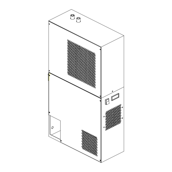
- Page 11 CPN: 85616902 --- DS15- - H---DS100- - H Fig. 4 Overall dimensions filter / separator discharge tube supply cable condensate drain tube air inlet air outlet...
- Page 12 Fig. 4 Overall dimensions dimensions --- inches (mm) model model L / M 17.7 32.1 19.7 DS15- - H (450) (815) (197) (500) (73) (82) (133) DS25- - H 23.6 23.6 39.0 39.0 11.1 11.1 22.6 22.6 (600) (990) (282) (575) (77) (177)
- Page 13 CPN: 85616902 --- DS15- - H---DS100- - H Fig. 6 Refrigerant diagram Fig. 7 Calibration COMPONENT MODEL SETTING AIR OUTLET AIR INLET 1. compressor 2. refrigerant condenser 3. fan motor Automatic expansion valve 4. evaporator 5. separator 7. expansion automatic valve 8.
- Page 14 Fig. 8 Spare Parts List (see Fig. 9) Fig. 9 Parts Codes Part Part DS15- - H DS25- - H DS35- - H DS50- - H DS75- - H DS100- - H 89328223 89328231 89328249 89328256 89327704 85611879 89327712 89327720 89327738 89327746 89320691...
- Page 15 CPN: 85616902 --- DS15- - H---DS100- - H Fig. 10 Electrical diagram 115V 1~ 60Hz only for model > > DS50- - H---DS100- - H Inn=0.03A RECOMMENDED and generally demanded by law (by installer) only for model DS100- - H...
- Page 16 English -- Legend LABELS DRAWINGS S Model 1. MC compressor S Serial No. refrigerant condenser S Low/High side refrigeration circuit design pressure 3. EV1 fan motor S Max air pressure evaporator S Max air inlet S Min. ambient separator Max ambient expansion automatic valve S Power supply Electrical diagram no.
Need help?
Do you have a question about the DS15-H and is the answer not in the manual?
Questions and answers