Table of Contents
Advertisement
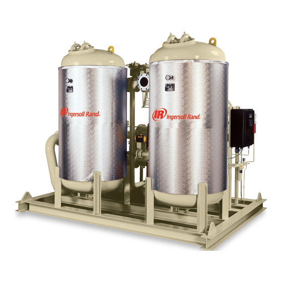
SERIES HC
Heat-of-Compression
Compressed Air Dryer
Models HC-3 – HC-239
IMPORTANT! BEFORE INSTALLING AND
OPERATING THE DRYER, IT IS
RECOMMENDED THAT THIS
MANUAL BE STUDIED AND
CLEARLY UNDERSTOOD.
THIS DRYER IS DESIGNED TO BE
USED ONLY WITH A NON-
LUBRICATED COMPRESSOR. USE
WITH A LUBRICATED
COMPRESSOR WILL VOID ALL
WARRANTIES AND MAY CAUSE
SEVERE DAMAGE.
Information
When making inquiries,
please provide the following
information:
1) Equipment Model Number
2) Equipment Serial Number
3) Equipment Operating
Pressure
4) Equipment Operating
Temperature
5) Approximate time in
service
6) Nature of Problem
For information, parts,
or service, contact your
I
n
g
e
r
s
o
l
l
-
R
a
n
d
I
n
g
e
r
s
o
l
l
-
R
a
n
d
local
Service provider or
reach us at
www.air.irco.com
Advertisement
Table of Contents

Related Manuals for Ingersoll-Rand HC-3


Summary of Contents for Ingersoll-Rand HC-3
- Page 1 Compressed Air Dryer 2) Equipment Serial Number 3) Equipment Operating Pressure 4) Equipment Operating Temperature Models HC-3 – HC-239 5) Approximate time in service 6) Nature of Problem IMPORTANT! BEFORE INSTALLING AND For information, parts, OPERATING THE DRYER, IT IS...
- Page 2 AIR COMPRESSOR GROUP BONDED WARRANTY & REGISTERED START UP Warranty The Company warrants that the equipment manufactured by it and delivered hereunder will be free of defects in material and workmanship for a period of twelve months from the date of placing the Equipment in operation or eighteen months from the date of shipment from the factory, whichever shall first occur.
-
Page 3: Table Of Contents
USER MANUAL Series HC INDEX PREFACE SECTION 1: INTRODUCTION General Information Safety Instructions 1.2.1 Identification of signs and symbols in this manual 1.2.2 Safety tips for maintenance, inspection & assembly work Personnel Qualification Product Information 1.4.1 Theory of Operation 1.4.2 Pressure vessel regulations 1.4.3 Airtightness test... - Page 4 Assembly and installation 4.4.4 Maintenance 4.4.5 Changing of filter elements 4.4.6 Accessories SECTION 5: SPARE PARTS LIST Recommended spares for HC-3 TO HC-239 SECTION 6: TROUBLESHOOTING AND FAULTS Introduction High Dewpoint Fail-to-shift Primary Drain Failure Secondary Drain Failure Short-term shut-down Shut-down in case of a fault or for maintenance Reference No.
- Page 5 USER MANUAL Series HC SECTION 7: I-R ACTIVATED ALUMINA MSDS Company Description Material Description Ingredients Physical Data Fire and Explosion Data Reactivity Data Health Hazard Information Spill, Leak, and Disposal Procedures Special Protection Information 7.10 Special Precautions and Comments 7.11 References SECTION 8: AUXILIARY MANUALS &...
- Page 6 USER MANUAL Series HC PREFACE: ® is an aid in getting to know the adsorption ® This technical manual from dryer better and in utilizing its possibilities for application in accordance with its intended use. Furthermore, this manual contains important information for safe, proper and economic operation.
-
Page 7: General Information
SECTION 1: GENERAL INFORMATION The adsorption dryer of the HC-3 – HC-239 series is built according to the latest technological developments and recognized safety rules. Its use, however, can endanger life and limb of the user or of third parties and can lead to considerable damage to the adsorption dryer and other material assets if: •... -
Page 8: Safety Tips For Maintenance, Inspection & Assembly Work
USER MANUAL Series HC SECTION 1: (Continued) 1.2.1 Identification of signs and symbols in this technical manual The safety tips contained in this technical manual, whose disregard could endanger people and machines, are indicated by a general danger sign and the additional markings Danger! Or Attention! Danger! / Attention! Warning against electrical voltage! -
Page 9: Personnel Qualification
1.2.2 Safety tips for maintenance, inspection and assembly work (Continued) Attention! − Never make structural changes to the adsorption dryer that are not specifically authorized by Ingersoll-Rand! − Only use original spare and accessory parts! − Carry out maintenance work only when the adsorption dryer is switched off, depressurized,... -
Page 10: Product Information
USER MANUAL Series HC SECTION 1: (Continued) PRODUCT INFORMATION The adsorption dryer is used for the purpose of drying compressed air and other gases according to its respective design. As a "standard model" the adsorption dryer is equipped with two desiccant vessels and, depending on certain conditions, provides pure, dry and oil-free compressed air or gases. - Page 11 USER MANUAL Series HC SECTION 1: (Continued) A. Regeneration Cycles 1. Heating. Hot air directly from the compressor enters the inlet of the HC and is directed by the inlet 2-way valves into the regenerating tower. This hot, thirsty air regenerates the bulk of the water from the desiccant. The air is then directed into the aftercooler where it is cooled, the coalescing separator where liquid water is removed through the drain trap system, then into the drying tower where the air is actually dried to its final low...
- Page 12 USER MANUAL Series HC SECTION 1: (Continued) 2. Stripping. At the end of heating, the inlet valves shift position, directing the hot inlet air directly into the aftercooler, separator, and drying tower. We now begin stripping. The stripping phase of regeneration lasts 90 minutes.
- Page 13 USER MANUAL Series HC SECTION 1: (Continued) 3. Cooling. At the end of stripping, the regenerating tower is repressurized. The cooling cycle valves open and cooling begins. The cooling cycle lasts 60 minutes. During cooling, a portion of the dry outlet air is directed into the regenerating tower to reduce the temperature of the bed prior to tower shift.
-
Page 14: Pressure Vessel Regulations
The pressure vessels are designed according to the standard technical requirements. They fulfill the test of the certifying procedure and carry the “U”, “UM” ASME Symbol. Range of Application: Type HC-3 – HC-239 Operating overpressure Max. 150 PSIG Max. 500°F Operating Temperature Min. -
Page 15: Technical Data Sheet
USER MANUAL Series HC SECTION 1: (Continued) 1.4.5 Technical data sheet MODEL HC-3 HC-6 HC-7 HC-9 Flow (SCFM) @ 100 PSIG 100°F Drying Temperature Vessel OD – Inches Desiccant type IR Activated Alumina Lbs. Desiccant / Vessel Inlet connection 2 NPT... - Page 16 USER MANUAL Series HC SECTION 1: (Continued) 1.4.5 Technical data sheet MODEL HC-14 HC-21 HC-30 HC-41 Flow (SCFM) @ 100 PSIG 1204 1880 2708 3686 100°F Drying Temperature Vessel OD – Inches Desiccant type IR Activated Alumina Lbs. Desiccant / Vessel 1395 2009 2735...
- Page 17 USER MANUAL Series HC SECTION 1: (Continued) 1.4.5 Technical data sheet MODEL HC-54 HC-69 HC-85 HC-103 Flow (SCFM) @ 100 PSIG 4814 6093 7522 9101 100°F Drying Temperature Vessel OD – Inches Desiccant type IR Activated Alumina Lbs. Desiccant / Vessel 3572 4521 5581...
- Page 18 USER MANUAL Series HC SECTION 1: (Continued) 1.4.4 Technical data sheet MODEL HC-122 HC-143 HC-166 Flow (SCFM) @ 100 PSIG 10832 12712 14742 100°F Drying Temperature Vessel OD – Inches Desiccant type IR Activated Alumina Lbs. Desiccant / Vessel 8037 9432 10939 Inlet connection...
-
Page 19: Dryer Flow Capacities
Series HC SECTION 1: (Continued) 1.4.6 Dryer Flow Capacities Model Selection Chart: MODEL 85 PSI 90 PSI 95 PSI 100 PSI 105 PSI 110 PSI 115 PSI HC-3 HC-6 HC-7 HC-9 1046 1094 1146 1204 1253 1308 1368 HC-14 HC-21... -
Page 20: Transport
USER MANUAL Series HC SECTION 1: (Continued) 1.4.7 Transport After the adsorption dryer has been delivered, it must be checked for damage that may have occurred during transport. The Transport Company must be informed to register any damage. Shipping damage is not covered by any warranty. 1.4.8 Storage If the adsorption dryer is to be stored for a prolonged period of time, it should be stored in a dry place, preferably indoors;... -
Page 21: Set-Up And Installation
INSTALLATION SET-UP AND INSTALLATION Once at the installation location, the adsorption dryers of the series HC-3 – HC-239, which are supplied with a base frame, must be positioned so that all sides are easily accessible. Should vibrations occur on the installation location, the adsorption dryer is to be placed onto vibration dampeners. -
Page 22: Mechanical Installation
USER MANUAL Series HC SECTION 2: (Continued) 2.1.1 Mechanical installation The equipment should be located in an area as practically possible with adequate clearances for service. An overhead clearance of not less than three feet above each adsorber tower is required for loading of the desiccant. Access clearance of three feet in front of the control panel should be provided. -
Page 23: Filter Installation
USER MANUAL Series HC SECTION 2: (Continued) 2.1.2 Filter installation Series HC dryers are shipped with the afterfilter loose or with the filter skid mounted on a separate steel frame. The following installation applies to all models that are shipped with filters loose. Afterfilter Installation •... -
Page 24: Electrical Installation
USER MANUAL Series HC SECTION 2: (Continued) 2.1.3 Electrical installation • Connect the dryer to a correctly sized power supply. The dryer requires a 115V 60 cycle connection. A disconnect switch is not provided with the dryer and must be supplied by end user in accordance with the recognized electrical codes. -
Page 25: Pressurizing Dryer
USER MANUAL Series HC SECTION 3: START UP AND OPERATION START UP Attention! All pipes and wire connections are to be tightened! Furthermore, before start-up: − The pipes must be checked for the presence of scale, abraded material from the threading, or other similar impurities. -
Page 26: Energizing Dryer Controls
USER MANUAL Series HC SECTION 3: (Continued) 3.1.1 Pressurizing dryer (Continued) • When pressurizing is complete then fully open the system outlet valve to place the equipment in service. • Verify the system inlet pressure and temperature are at the design operating levels. - Page 27 USER MANUAL Series HC SECTION 3: (Continued) OPERATOR INTERFACE Function keys F1 through F4 perform the function displayed on the screen. ARROWS ALLOW USER TO SCROLL UP OR DOWN INSIDE OF THE SCREEN LIST SELECTOR. AN ARROW ON THE RIGHT SIDE OF THE SCREEN NAMES INDICATES WHICH SCREEN IS BEING SELECTED.
- Page 28 USER MANUAL Series HC SECTION 3: (Continued) 3.2.1 Main Screen This is the main screen. This screen will be displayed upon initial startup or after an alarm has been cleared. Using the up or down arrow keys and the enter key you may select a screen to view.
- Page 29 USER MANUAL Series HC SECTION 3: (Continued) 3.2.3 Settings The settings screen allows you to toggle between Dewpoint Demand and straight Time cycle. While in Time cycle, the dryer will shift towers every four hours. When utilizing the optional DPDS, the dryer will complete its four hour regeneration and go into a standby mode until the outlet dewpoint has reached the dewpoint monitor’s set point.
- Page 30 USER MANUAL Series HC PROGRAM STEPS: (Continued) Part numbers for the instrument abbreviations listed in the program steps below (i.e. V1, V2, etc.) can be found in the Spare Parts List in Section 5 of this User Manual. STEP TIME DESCRIPTION OF ACTION 0 min.
- Page 31 USER MANUAL Series HC PROGRAM STEPS: (Continued) 240 min. If the dewpoint rises above the analyzer set-point or the Dewpoint/ +stdby Timer selector switch is on Timer then; De-energize SV5-1; Closes V13 De-energize SV1-1 Energize SV1-2 Opens V4, 5, 7 & 10 Closes V3, 6, 8 &...
- Page 32 USER MANUAL Series HC PROGRAM STEPS: (Continued) 480 min. If the dewpoint rises above the analyzer set-point or the Dewpoint/ +stdby Timer selector switch is on Timer then; De-energize SV5-1; Closes V13 GOTO STEP 1 NOTES: 1.) At any time during the cycle, if Inlet temperature (TH1) drops below the setpoint (240°F) then;...
- Page 33 USER MANUAL Series HC SECTION 4: MAINTENANCE Advice: In order to ensure continuous and trouble-free operation, a maintenance contract with d is recommended. SUGGESTED PREVENTIVE MAINTENANCE SCHEDULE 4.1.1 Introduction The Series HC compressed air dryer requires a minimum of maintenance as most components are "maintenance-free".
- Page 34 USER MANUAL Series HC SECTION 4: (Continued) 2. Isolate and depressurize the dryer. 3. Disconnect power to the dryer. 4. Replace afterfilter elements (the proper number and quantity is indicated on the filter and in the Spare Parts List in Section V of this manual). 5.
- Page 35 3. Refill both vessels with the proper amount of desiccant as noted in the specifications at the front of this manual. NOTE: Desiccant can be purchased only through Ingersoll-Rand distributors authorized to sell Series HC dryers and related products.
- Page 36 USER MANUAL Series HC SECTION 4: (Continued) D. ADJUSTMENTS The inlet air temperature (as indicated on the Instrument Panel) should be adjusted to obtain the desired temperature/dewpoint performance (reference the Regenerative Dryer Specification Sheet in Section I). This can be accomplished through manipulation of the inlet piping insulation and/or the compressor intercooling.
- Page 37 USER MANUAL Series HC SECTION 4: (Continued) DEWPOINT METER MAINTENANCE (DPDS Option only) NOTE: Refer to the Dewpoint Demand Installation & Operating Guide included with this User Manual for information on dewpoint meter maintenance and operation. FILTERS 4.4.1 General comments and use Filters of the series AF are suitable for filtering solids out of compressed air and other neutral, compressed gases.
- Page 38 USER MANUAL Series HC SECTION 4: (Continued) 4.4.5 Changing of filter elements Danger! The soiled filter elements are changed only when the housings are DEPRESSURIZED! Filter elements are to be changed according to the following steps: • Open the hand hole. •...
-
Page 39: Recommended Spare Parts List
USER MANUAL Series HC SECTION 5: RECOMMENDED SPARE PARTS LIST RECOMMENDED SPARE PARTS FOR HC-3 TO HC-14 Part No. Description HC-3 HC-6 – HC-7 HC-9 HC-14 38338737 Probe, for Dewpoint Demand option 38338745 Thermocouple, armoured, 12’ 38335600 Filter, particle removal, miniature, inline, ¼”, for DPDS option... - Page 40 USER MANUAL Series HC SECTION 5: (Continued) RECOMMENDED SPARE PARTS LIST RECOMMENDED SPARE PARTS FOR HC-21 TO HC-54 Part No. Description HC-21 HC-30 HC-41 HC-54 38338737 Probe, for Dewpoint Demand option 38338745 Thermocouple, armoured, 12’ 38335600 Filter, particle removal, miniature, inline, ¼”, for DPDS option 38335592 812-1B filter element...
- Page 41 USER MANUAL Series HC SECTION 5: (Continued) RECOMMENDED SPARE PARTS LIST RECOMMENDED SPARE PARTS FOR HC-69 TO HC-122 Part No. Description HC-69 HC-85 HC-103 HC-122 38338737 Probe, for Dewpoint Demand option 38338745 Thermocouple, armoured, 12’ 38335600 Filter, particle removal, miniature, inline, ¼”, for DPDS option 38335592 812-1B filter element...
- Page 42 USER MANUAL Series HC SECTION 5: (Continued) RECOMMENDED SPARE PARTS LIST RECOMMENDED SPARE PARTS FOR HC-143 TO HC-239 HC-186 – Part No. Description HC-143 HC-166 HC-239 HC-211 38338737 Probe, for Dewpoint Demand option 38338745 Thermocouple, armoured, 12’ 38335600 Filter, particle removal, miniature, inline, ¼”, for DPDS option 38335592 812-1B filter element...
- Page 43 USER MANUAL Series HC SECTION 5: (Continued) Legend: BE = visual moisture indicator CS = separator F = filter FS = float switch FT = primary float trap P = pressure gauge PRV = pressure relief valve SD = secondary drain SV = solenoid valve T = temperature gauge TW = thermowell...
- Page 44 USER MANUAL Series HC SECTION 6: TROUBLESHOOTING & FAULTS INTRODUCTION Following proper preventive maintenance procedures will go far toward assuring trouble-free dryer performance; however, failures will still occur. This troubleshooting part will help to identify the source of the problem and to effect a remedy.
- Page 45 USER MANUAL Series HC SECTION 6: (Continued) 6.2.6 Two-way Valve Leakage Valve leakage here will allow relatively wet inlet air to leak into the dry outlet air stream, thereby raising the dewpoint of the composite air. Compare the dewpoint of the air at the dryer outlet to the dewpoint measured at the top (outlet) of the drying tower (i.e., at the relief valve location).
- Page 46 USER MANUAL Series HC SECTION 6: (Continued) SECONDARY DRAIN FAILURE 6.5.1 Solenoid Valve Failure When the liquid level rises above the primary float valve elevation and contacts the liquid level probe, a circuit is completed energizing the 3-way normally open solenoid valve depressurizing the secondary drain valve actuator.
- Page 47 USER MANUAL Series HC SECTION 7: IR ACTIVATED ALUMINA MSDS COMPANY DESCRIPTION Ingersoll-Rand Company Heavy Industrial Air Solutions 800-B Beaty Street, Davidson, NC 28036 For Product Information: Tel: (800) 247-8640 MATERIAL DESCRIPTION Chemical Name & Formula: Aluminum Oxide; A1 Other Designation:...
- Page 48 USER MANUAL Series HC PHYSICAL DATA Physical Form: Crystalline or gelatinous granules, pellets, or powder Boiling Temperature: Freeze-Melt Temperature: 3700°F (2038°C) Vapor Pressure (mm): Vapor Density (air = 1): Evaporation Rate: Specific Gravity: Density: Loose bulk: 39 – 52 lb./ft. (0.62 –...
- Page 49 USER MANUAL Series HC FIRE AND EXPLOSION DATA Flashpoint: Auto-Ignition Temp.: Flammability Limits in Air: Upper/Lower: NA Product is non-flammable; not an explosion hazard. REACTIVITY DATA With water: Generates heat With air: None With heat: None With strong oxidizers: None Non-corrosive HEALTH HAZARD INFORMATION The desiccant properties of Activated Alumina may cause irritation to the eyes and...
- Page 50 USER MANUAL Series HC SPILL, LEAK, & DISPOSAL PROCEDURES Clean up using dry procedures; avoid dusting. Waste may be considered as inert material, suitable for landfill. RCRA Hazardous Waste No.: Not federally regulated SPECIAL PROTECTION INFORMATION Use with adequate ventilation to meet the exposure limits as listed in Section 7.3. Where the exposure limit is or may be exceeded, use NIOSH approved respiratory protection.
- Page 51 USER MANUAL Series HC SECTION 8: AUXILIARY MANUALS & DRAWINGS Reference No. 145 Final Rev 5 Page 50 September 2004...
Need help?
Do you have a question about the HC-3 and is the answer not in the manual?
Questions and answers