Table of Contents
Advertisement
the benchmark for emc
Manual
f o r
O p e r a t i n g
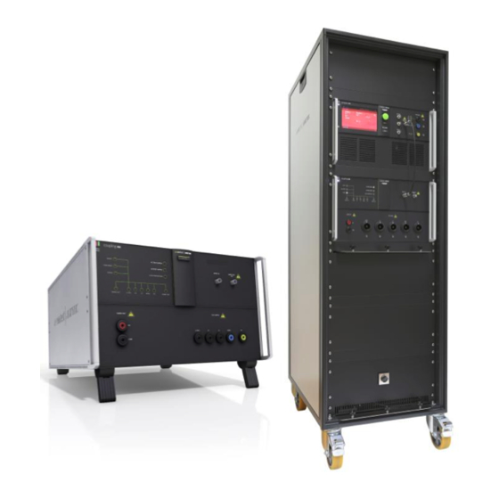
coupling NX series
3-phase coupling decoupling network
Testing of electronic modules with EFT/burst and 1.2/50s
Surge pulses up to 5 kV, 2.5 kA
The coupling NX series coupling decoupling network is used to
couples the surge and burst pulses from the compact NX5
generator to a three phase test object
(coupling as per. IEC standard).
The coupling NX coupling decoupling network is controlled from
EM Test transient generator of the compact NX- series.
Version: 1.03 / 30.01.2017
Replaces: 1.02 / 22.12.2016
Filename: UserManual-coupling-NX-E-V1.03.doc
Print date: 30.01.17
Burst, Surge Pulse as per.
– IEC 61000-4-4
– IEC 61000-4-5
Advertisement
Table of Contents

Related Manuals for EM TEST coupling NX5 bs-3-480-16

Summary of Contents for EM TEST coupling NX5 bs-3-480-16
- Page 1 (coupling as per. IEC standard). The coupling NX coupling decoupling network is controlled from EM Test transient generator of the compact NX- series. Version: 1.03 / 30.01.2017 the benchmark for emc Replaces: 1.02 / 22.12.2016 Filename: UserManual-coupling-NX-E-V1.03.doc...
- Page 2 Switzerland Phone : +41 61 717 91 91 Fax : +41 61 717 91 99 URL : http://www.emtest.com Copyright © 2017 EM TEST (Switzerland) GmbH All right reserved. Specifications subject to change Manual of operation V 1.03 2 / 53...
-
Page 3: Table Of Contents
Operating Functions ........................... 15 5.1. coupling NX5 bs-3-480-16 / 32 ......................15 5.1.1. Front view coupling NX5 bs-3-480-16 / 32 ..................15 5.1.2. Rear side coupling NX5 bs-3-480-16 / 32 ................... 16 5.2. Rack with built in coupling NX5-bs-480-125 ..................17 5.2.1. - Page 4 11.2. Accessories and options ........................37 Appendix ..............................38 12.1. Declaration of CE-Conformity ......................38 12.1.1. Declaration of CE-Conformity Coupling Network coupling NX5 bs-3-480-16 / 32 ......38 12.1.2. Declaration of CE-Conformity Coupling Network coupling NX5 bs-3-480-xx.1 ......39 12.1.3.
-
Page 5: General
EM TEST will, at its expense, deliver the repaired or replaced product or parts to the buyer. Any warranty of EM TEST will not apply if the buyer is in default under the purchase order agreement or where the product or any part thereof: ... -
Page 6: Product Return Procedure
The EM TEST coupling NX series couplers are dedicated under category 9 in the directive 2012/19/EU (WEEE). The product should be recycled through a professional organization with appropriate experience for the disposal and recycling of electronic products. EM TEST is also available to help with questions relating to the recycling of this equipment. -
Page 7: Safety Information
EM TEST coupling NX Safety information Before using this equipment, read the operating manual and the separate delivered safety manual carefully Attention 2.1. Intended use The “compact NX” test system with his coupling NX series is designed primarily for conducted transient interference tests as specified in the European generic standards IEC/EN 61000-6-1 to cover equipment for household, office and light industrial use, and IEC/EN 61000-6-2 for applications in industrial environments. -
Page 8: Qualification Of Personnel
Neither AMETEK CTS, or EM TEST (Switzerland) GmbH, nor any of the subsidiary sales organizations can accept any responsibility for personnel, material or inconsequential injury, loss or damage that results from improper use of the equipment and accessories. -
Page 9: Installation Put In Service
EM TEST coupling NX Installation put in service This chapter includes a checklist with steps that should be taken before the coupling NX series is switched on and put into operation. 3.1. Safety instructions for installation and initial installation National regulations in installation and operation of electrical equipment must be respected. -
Page 10: Installation Of The Coupling Nx Series
Do not dispose of packaging materials. All packaging should be retained in the event that NOTE the instrument or any of its accessories should need to be returned to a EM TEST service center for repair or calibration. Using the following list, check that all the items ordered have been delivered:... -
Page 11: Grounding And Power Connection
EM TEST coupling NX 3.2.2. Grounding and power connection Two independent ground connections are necessary- one for the test system and one for the EUT. These must be connected back to the local permanent installation or to a fixed, permanent ground conductor. To avoid electric shock, the power cord protective grounding conductor must be connected to ground. -
Page 12: Mains Switch And Fuse
EM TEST coupling NX 3.2.3. Mains Switch and fuse The mains power voltage indicated on the instrument must correspond with the local supply voltage (mains voltage: 85–265 Vac, universal power unit, mains frequency: 50–60 Hz). To replace a fuse: 1) Disconnect the mains cable... -
Page 13: Connecting System Coupling Nx With Compact Nx5 Generator
HV cable. It is recommended to connect the simulator to the ground reference plane of the test set-up. Figure 6.1: Example of a test rack with compact NX5 and coupling NX5 bs-3-480-16 Connect the following cables between the generator and coupling network... -
Page 14: List Of Coupling Networks
Device for 3 x 690 V EUT ac EUT dc EUT Current [A] Housing voltage [V] voltage [V] coupling NX5 bs-3-480-16 3 x 480 19’’, 6 HU coupling NX5 bs-3-480-32 3 x 480 19’’, 6 HU coupling NX5 bs-3-480-63 3 x 480... -
Page 15: Operating Functions
Operating Functions 5.1. coupling NX5 bs-3-480-16 / 32 5.1.1. Front view coupling NX5 bs-3-480-16 / 32 Figure 5.1: coupling NX front side ( model for 5kV/16 A / 32 A ) Active LED EFT input from compact NX generator Phenomenon (Burst, Ring Wave, Surge) -
Page 16: Rear Side Coupling Nx5 Bs-3-480-16 / 32
EM TEST coupling NX 5.1.2. Rear side coupling NX5 bs-3-480-16 / 32 Figure 5.2 : Rear side coupling NX 1 Reference earth connection (Screw M4) 5 Power switch 2 EUT power L1 & dc+, L2, L3, N & dc-, PE 6 Mains connector and fuse (5 x 20 mm) 3 Input HV &... -
Page 17: Rack With Built In Coupling Nx5-Bs-480-125
Indication LED and output plugs of the coupling NX5 bs-3-480-125. See the previous chapter 5.1.1. Front view coupling NX5 bs-3-480-16 / 32 for explain all functions. EUT output L1, L2, L3, N, PE; 6mm Input plug for the EUT power supply (6 mm safety banana plug up to 125A). The input is not fused. -
Page 18: Connecting Plate Coupling Nx5 Bs-3-480-125 Rack
EM TEST coupling NX 5.2.2. Connecting plate coupling NX5 bs-3-480-125 Rack Figure 5.4: coupling NX font view (model for 5kV/100 A / 16 A) EUT AC supply input 3 x 400 V / 100A Control Out 0-10Vdc EUT supply input PF1 / N, PE;... -
Page 19: Rack With Built In Coupling Nx5-Bs-3-690-200.3
EM TEST coupling NX 5.3. Rack with built in Coupling NX5-bs-3-690-200.3 5.3.1. Front and rear view coupling NX5-bs-3-690-200.3 Generator compact NX5 Screw for open rear cover CDN coupling NX5 bs-3-690-200.x front Rear cover EUT Output 200 A 10 Current range selector switch... -
Page 20: Front And Rear View Coupling Nx5 Bs-3-690-200.X
EM TEST coupling NX 5.3.2. Front and rear view coupling NX5 bs-3-690-200.x Figure 5.3: Test system with compact NX5b, coupling NX5 (model for EUT 3 x 400V /100 A Active LED EFT input from compact NX generator Phenomenon (Burst, Ring Wave, Surge) -
Page 21: Connecting Plate Coupling Nx5 Bs-3-690-200.3 Rack
EM TEST coupling NX 5.3.3. Connecting plate coupling NX5 bs-3-690-200.3 Rack Figure 5.4: coupling NX rear view EUT AC supply input 3 x 690 V / 200A Control Out 0-10VDC EUT DC supply input 1000 V / 200A Auxiliary not used EUT supply input PF1 / N, PE;... - Page 22 EM TEST coupling NX Figure 5.4: coupling NX rear view EUT AC supply input 3 x 690 V / 200A Control Out 0-10VDC EUT DC supply input 1000 V / 200A Auxiliary not used EUT supply input PF1 / N, PE;...
-
Page 23: Current Range Selector Nx5 Bs-3-690-200
EM TEST coupling NX 5.3.4. Current Range selector NX5 bs-3-690-200 At the rear side is the current range selector switch. It is a mechanical drum switch for adapt the inductance of the decoupling inductor to the current range. Fig: 5.5... -
Page 24: General
EM TEST coupling NX General The coupling network has to couple the transients well defined to the lines of a power supply system. The coupling is realized by discrete coupling capacitors, having a sufficient voltage capability and bandwidth. The specification is given in IEC 61000-4-4, IEC 61000-4-5. -
Page 25: Surge Coupling Decoupling Networks Rated Up To 200 A
EM TEST coupling NX 6.3. Surge coupling decoupling networks rated up to 200 A The voltage drop across the CDN shall not exceed 10 % of the CDN input voltage at the specified current rating, but should not exceed 1.5 mH. -
Page 26: Technical Data Coupling Nx
Device EUT nominal Inrush Max. Weight [kg] Dimension @230V Current 50 Hz 60 Hz 19” 6HU coupling NX5 bs-3-480-16 16 A 244 A 203 A app. 30 kg 19” 6HU coupling NX5 bs-3-480-32 32 A 305 A 254 A app. 45 kg 19”... -
Page 27: Technical Data Coupling Nx5 Bs-3-690-Xx.y
EM TEST coupling NX 7.1.2. Technical data coupling NX5 bs-3-690-xx.y Device EUT nominal Inrush Max. Weight [kg] Dimension @230V Current 50 Hz 60 Hz 19” 6HU coupling NX5 bs-3-690-16 16 A 244 A 203 A app. 30 kg 19” 6HU... -
Page 28: Technical Data Coupling Nx5 Bs-3-690-Xx.2 And Coupling Nx5 Bs-3-690-Xxx.3
EM TEST coupling NX 7.1.3. Technical data coupling NX5 bs-3-690-xx.2 and coupling NX5 bs-3-690-xxx.3 Device EUT nominal Inrush Max. Weight [kg] Dimension @230V current [ac/dc] 50 Hz 60 Hz 19” rack, 34 HU coupling NX5 bs-3-690-16.2 16 A 244 A 203 A app. -
Page 29: Coupling Capacitors And Decoupling Inductances
EM TEST coupling NX 7.2. Coupling capacitors and decoupling inductances 7.2.1. Burst coupling to capacitive coupling clamp for signal- and data lines Burst coupling as per IEC 61000-4-4 Coupling Coupling Coupling capacitor all combinations Supply lines Common mode all combinations L1, L2, L3, N, PE 33 nF SHV 50 Ω... -
Page 30: Dc Current Capability Of Coupling Nx Devices
EM TEST coupling NX 7.3. DC current capability of coupling NX devices Coupler models with a built in ac mains contactor have a reduced dc switching capability. This current rate depends on the following parameters: contactor model, applied dc voltage and time constant L/R of the dc circuit... -
Page 31: General
EM TEST coupling NX 7.4. General 7.5. Control supply and Safety Control supply Mains (control) 85 V - 264 V, 50/60 Hz Power Approx. 50 W Fuses device supply 115 V: 2 x 2 A slow blow, 230 V: 2 x 2 A slow blow Fuses Rack system supply 115 V: 2 x 6.3 A slow blow,... -
Page 32: Operation
EM TEST coupling NX Operation 8.1. Power supply input (EUT) The power supply input for the EUT is located at the rear side of the coupler. Adapters for customized three phase connectors have to be realized by the user himself or can be manufactured on customer’s specification. -
Page 33: Operation With Coupling Nx Or Generator Internal Cdn
EM TEST coupling NX 8.3. Operation with coupling NX or generator internal CDN The coupling network of the coupling NX is operated and controlled via the compact NX generator. After power on, the compact NX generator scans the system for searching all devices. -
Page 34: Test Set Up
EM TEST coupling NX Test set up 9.1. Test setup for Burst impulses Coupling to power lines via coupling NX Figure 9.1 Coupling to signal and data lines via an external capacitive coupling clamp. Figure 9.2 9.2. Test level with Burst as per IEC 61000-4-4 Ed.2. -
Page 35: Test Setup For Surge Impulses
EM TEST coupling NX 9.3. Test setup for Surge impulses 9.3.1. Surge coupling to power lines Coupling of surge impulses to power lines via coupling NX as per IEC 61000-4-5 Figure 9.3 9.3.2. Surge coupling to signal- and data lines... -
Page 36: Maintenance And Calibration
EM TEST equipment. EM TEST doesn’t know each customer’s Quality Assurance Policy nor do we know how often the equipment is used and what kind of tests is performed during the life cycle of test equipment. Only the customer knows all the details and therefore the customer needs to specify the calibration interval for his test equipment. -
Page 37: Delivery Groups
EM TEST coupling NX Delivery Groups 11.1. Basic equipment coupling NX network, type coupling NX series 1 Power mains cable for the coupler supply, country coded 1 HVS – Banana – Banana, 0.5 Meter HV cable, 1 x red, 1 x black ... -
Page 38: Appendix
EM TEST coupling NX Appendix 12.1. Declaration of CE-Conformity 12.1.1. Declaration of CE-Conformity Coupling Network coupling NX5 bs-3-480-16 / 32 Manufacturer: EM TEST (Switzerland) GmbH Address: Sternenhofstr. 15 CH 4153 Reinach Switzerland Declares, that under is sole responsibility, the product’s listed below, including all their options, are conformity with the applicable CE directives listed below using the relevant section of the following EC standards and other normative documents. -
Page 39: Declaration Of Ce-Conformity Coupling Network Coupling Nx5 Bs-3-480-Xx.1
EM TEST coupling NX 12.1.2. Declaration of CE-Conformity Coupling Network coupling NX5 bs-3-480-xx.1 Manufacturer: EM TEST (Switzerland) GmbH Address: Sternenhofstr. 15 CH 4153 Reinach Switzerland Declares, that under is sole responsibility, the product’s listed below, including all their options, are conformity with the applicable CE directives listed below using the relevant section of the following EC standards and other normative documents. -
Page 40: Declaration Of Ce-Conformity Coupling Network Coupling Nx5 Bs-3-690-16 / 32
EM TEST coupling NX 12.1.3. Declaration of CE-Conformity Coupling Network coupling NX5 bs-3-690-16 / 32 Manufacturer: EM TEST (Switzerland) GmbH Address: Sternenhofstr. 15 CH 4153 Reinach Switzerland Declares, that under is sole responsibility, the product’s listed below, including all their options, are conformity with the applicable CE directives listed below using the relevant section of the following EC standards and other normative documents. -
Page 41: Declaration Of Ce-Conformity Coupling Network Coupling Nx5 Bs-3-690-Xx.1
EM TEST coupling NX 12.1.4. Declaration of CE-Conformity Coupling Network coupling NX5 bs-3-690-xx.1 Manufacturer: EM TEST (Switzerland) GmbH Address: Sternenhofstr. 15 CH 4153 Reinach Switzerland Declares, that under is sole responsibility, the product’s listed below, including all their options, are conformity with the applicable CE directives listed below using the relevant section of the following EC standards and other normative documents. -
Page 42: Declaration Of Ce-Conformity Coupling Network Coupling Nx5 Bs-3-690-Xx.2
EM TEST coupling NX 12.1.5. Declaration of CE-Conformity Coupling Network coupling NX5 bs-3-690-xx.2 Manufacturer: EM TEST (Switzerland) GmbH Address: Sternenhofstr. 15 CH 4153 Reinach Switzerland Declares, that under is sole responsibility, the product’s listed below, including all their options, are conformity with the applicable CE directives listed below using the relevant section of the following EC standards and other normative documents. -
Page 43: Declaration Of Ce-Conformity Coupling Network Coupling Nx5 Bs-3-690-Xx.3
EM TEST coupling NX 12.1.6. Declaration of CE-Conformity Coupling Network coupling NX5 bs-3-690-xx.3 Manufacturer: EM TEST (Switzerland) GmbH Address: Sternenhofstr. 15 CH 4153 Reinach Switzerland Declares, that under is sole responsibility, the product’s listed below, including all their options, are conformity with the applicable CE directives listed below using the relevant section of the following EC standards and other normative documents. -
Page 44: General Diagram
EM TEST coupling NX 12.2. General diagram 12.2.1. General diagram coupling NX5 models for 16 A and 32 A Manual of operation V 1.03 44 / 53... -
Page 45: General Diagram Test System Coupling Nx5-B - 100A
EM TEST coupling NX 12.2.2. General diagram Test System Coupling NX5-b - 100A Manual of operation V 1.03 45 / 53... -
Page 46: General Diagram Test System Compact Nx5-Bs Coupling 125 A
EM TEST coupling NX 12.2.3. General diagram Test System Compact NX5-bs Coupling 125 A Manual of operation V 1.03 46 / 53... -
Page 47: General Diagram Test System Compact Nx5-Bs Coupling Nx5 Bs-3-690-200.3
EM TEST coupling NX 12.2.4. General diagram Test System compact NX5-bs coupling NX5 bs-3-690-200.3 Manual of operation V 1.03 47 / 53... -
Page 49: Inrush Current
EM TEST coupling NX 12.3. Inrush current The inrush current depends from the mains impedance, the inductance of the surge inductors and the EUT impedance. The inrush current in the tables below are theoretical maximum, calculated with the decoupling inductance only. These values cannot be reached in a real system. -
Page 50: 100 A Plugs And Connectors From Multi Contact
EM TEST coupling NX 12.4. 100 A Plugs and connectors from Multi Contact Safety sockets KBT6AR-N/...-S with snap-in lock and crimp connection Model KBT6AR-N/...-S safety sockets are sockets with locking devices and for crimping onto highly flexible Cu conductor with cross-sections of 10mm2, 16mm2 or 25mm2. -
Page 51: 200 A Plugs And Connectors From Multi Contact
EM TEST coupling NX 12.5. 200 A Plugs and connectors from Multi Contact Introduction ...10BV... Single-pole round connectors, insulated, Ø 10mm with bayonet locking The MC Connectors may be used as “connectors for class II equipment”. The connector itself meets the requirements of double and/or reinforced insulation. -
Page 52: Multi Contact Mc Locking System (Ar-System)
EM TEST coupling NX 12.5.1. Multi Contact MC Locking system (AR-system) The MC Locking system (AR) operates on the “push-pull” principle. It is self – locking when connected. Disconnection is effected by an axially displaceable coupling ring: first push, then pull to disconnect. Dirty parts should be cleaned with industrial alcohol before connecting. -
Page 53: Multi Contact Mc Crimping Materials
EM TEST coupling NX 12.5.2. Multi Contact MC Crimping materials Manual of operation V 1.03 53 / 53...
Need help?
Do you have a question about the coupling NX5 bs-3-480-16 and is the answer not in the manual?
Questions and answers