Table of Contents
Advertisement
Quick Links
Advertisement
Table of Contents

Related Manuals for VIA Technologies EITX-3001


Summary of Contents for VIA Technologies EITX-3001
- Page 1 EITX-3001 Em-ITX Form Factor SBC 112-07022012-1050...
-
Page 2: Regulatory Compliance
However, VIA Technologies assumes no responsibility for the use or misuse of the information in this document and for any patent infringements that may arise from the use of this document. -
Page 3: Safety Precautions
Safety Precautions Do’s Always read the safety instructions carefully. Keep this User's Manual for future reference. All cautions and warnings on the equipment should be noted. Keep this equipment away from humidity. Lay this equipment on a reliable flat surface before setting it up. -
Page 4: Optional Accessories
Box contents and ordering information Model Number Description EITX-3001-1N13A1 Standard kit 1 x EITX-3001 board 1 x Mini-jumper pack 1 x SATA data cable 1 x SATA power cable (Supports 2.5” HDD only) 1 x Power cable, 2-pole Phoenix plug to... -
Page 5: Table Of Contents
ABLE OF ONTENTS 1 Product Overview ....................1 Key Features ......................2 Specifications ......................3 EITX-3001 Dimensions ..................7 Top side ....................... 7 Top side with heatsink ................. 8 Bottom side with heatsink ................. 8 Front I/O with heatsink ................9 Rear I/O with heatsink ................. - Page 6 LPC connector ....................28 System Thermal Sensor pin header ............29 System fan ......................29 Battery ........................30 SODIMM SDRAM memory slot ..............31 3 Onboard Jumpers .................... 33 LCD power select ....................34 COM3 and COM4 voltage select .............. 35 AT/ATX Power mode Select ................
- Page 7 H/W Health Function ................51 ACPI Settings ......................52 General ACPI Configuration ................ 53 Suspend Mode ....................53 Repost Video on S3 Resume ..............53 Advanced ACPI Configuration ..............54 ACPI Version Features ................54 ACPI APIC Support ..................54 AMI OEMB Table ..................
- Page 8 FreeDos Configuration ................... 64 Advanced PCI/PnP Settings................65 Clear NVRAM ....................65 Plug & Play O/S ..................... 65 PCI Latency Timer ..................65 Allocate IRQ to PCI VGA ................66 Palette Snooping ..................66 PCI IDE BusMaster ..................66 IRQ3~15 ......................66 DMA Channel 0~7 ..................
- Page 9 5 Driver Installation ....................79 Microsoft Driver Support ................80 Linux Driver Support ..................80 A Disassembling the EITX-3001 Board from Heatsink ......81 Disassembling the mainboard ..............82 B Installing the WLAN module ............... 85 Installing the WLAN USB module ............. 86...
-
Page 10: Product Overview
Product Overview... -
Page 11: Key Features
The VIA EITX-3001 is a high performance single board computer (SBC) with low power requirements based on the Embedded ITX (Em-ITX) form factor. Its low power requirements are made possible by its usage of energy efficient VIA Nano CPU. The EITX-3001 is designed for ultra-thin embedded applications and can withstand temperatures ranging from -10°C to 60°C. -
Page 12: Specifications
PECIFICATIONS Processor Core • VIA Nano Processor Logic System • Compact 21 mm x 21 mm NanoBGA2 package • Nano 1.3 GHz System Chipset • VIA VX855 Unified Digital Media IGP chipset • Supports 800 MHz Front Side Bus BIOS •... - Page 13 Gigabit Ethernet Controller • Onboard VIA VT6122 Gigabit Ethernet controller Interface • Supports one RJ45 connector • Supports Wake On LAN (WOL) • Support Preboot Execution Environment (PXE) Audio Controller • VIA VT1708B High Definition Audio Codec Interface • Support Line-in, Line-out, Mic-in connectors •...
- Page 14 Watchdog Timer Output • System reset Interval • Programmable 1~255 sec. I/O ports Front I/O coastline • One HDD & PWR LED • Two RS-232/422/485 COM port connectors as COM 1 and COM2 • One USB device port • One 2-pole of Phoenix power input connector •...
- Page 15 Onboard Power Consumption • Typical 18.5W DC to DC Power Supply Input Voltage • Built-in onboard DC-to-DC converter • Accept wide range of Power Input of DC 7V ~ 36V • Supports AT and ATX mode Power Input Connector • One 2-pole Phoenix connector AT/ATX •...
-
Page 16: Eitx-3001 Dimensions
EITX-3001 D IMENSIONS Top side... -
Page 17: Top Side With Heatsink
Top side with heatsink Bottom side with heatsink... -
Page 18: Front I/O With Heatsink
Front I/O with heatsink Rear I/O with heatsink... -
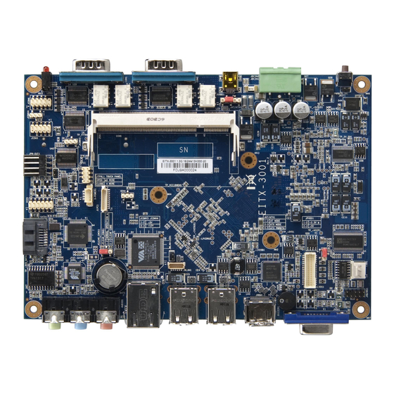
Page 19: Eitx-3001 Layout
EITX-3001 L AYOUT Top side Bottom side... - Page 20 Item Label Description FAN1 System Fan Power connector JKB/MS1 PS/2 keyboard and mouse pin header JPVDD1 PVDD1 LCD power select jumper JLVDS1 Onboard LVDS Panel connector JWLAN1 WLAN connector JWLAN-LED1 WLAN LED status indicator pin header BAT1 Battery socket for Lithium 3V/48mAh coin battery (Panasonic BR1225) JCLEAR_CMOS1...
-
Page 21: Front I/O Layout
The board comes with a 2-pole Phoenix connector that carries 7~36 VDC external power input. Signal +7V ~ 36V DC USB device port The EITX-3001 provides a USB device port in the front I/O face for quick data transfer to another computer. Signal +5VUSBD USBDP-... -
Page 22: Com Port Connectors
COM 2 can be configured in the BIOS Setup Utility to operate in RS-232, RS-422 or RS-485 mode. LED Indicators There are two LEDs on the EITX-3001 front I/O face for indicating system status: PWR LED is for power status (green) -
Page 23: Rear I/O Layout
I/O L AYOUT VGA Connector The EITX-3001 provides a high resolution VGA interface on the rear I/O coastline by a D-sub 15-pin connector to support a VGA CRT monitor. It supports resolution up to 1920 x 1440. The pin assignments for the VGA display are listed below. -
Page 24: Hdmi ® Port
DDCSDA Hot Plug Detect USB Port Connector The EITX-3001 can support up to four USB-interface connectors. By default it provides two USB port stacks located on the front I/O coastline. Each stack has two USB connectors. These USB-interface connectors give complete Plug & Play and hot swap capability for up to 127 external devices. -
Page 25: Lan Port: Gigabit Ethernet Port
LAN port: Gigabit Ethernet Port The EITX-3001 is equipped with a high performance PCI-Express VIA VT6122 Gigabit Ethernet controller. The controller is fully compliant with IEEE 802.3 (10BASE-T), 802.3u (100BASE-TX), and 802.3ab (1000BASE-T) standards. Signal LAN1_TD0+ LAN1_TD0- LAN1_TD1+ LAN1_TD1- LAN1_TD2+... -
Page 26: Audio Ports (Line-Out, Line-In And Mic-In)
Audio Ports (Line-out, Line-in and Mic-in) The EITX-3001 offers High Definition Audio through three 3.5 mm TRS jack connectors: Line-out, Line-in and Mic-in. The Line-out jack is for connecting to external speakers or headphones. The Line-In jack is for connecting to an external audio device such as a CD player, tape player, etc. -
Page 27: Onboard Connectors & Slots
Onboard Connectors & Slots This chapter provides information about hardware installation procedures. It is recommended to use a grounded wrist strap before handling computer components. Electrostatic discharge (ESD) can damage some components. -
Page 28: Lvds Panel Connector
LVDS PANEL CONNECTOR The EITX-3001 supports an onboard 24-bit single channel LVDS interface through a high density 30-pin (2x15-pin) wafer box connector. A detailed pin assignment of the 30-pin (2x15-pin) wafer box connector is shown below. Signal Signal IVDD1_5V +LD1C1... -
Page 29: Resistive Touch Panel Connector
ESISTIVE TOUCH PANEL CONNECTOR Signal R_UL R_UR R_POROBE R_LR R_LL... -
Page 30: Sata Connector
SATA C ONNECTOR The EITX-3001 board supports one Serial ATA port through its onboard connector: TP_+3V3SATA1. Data transfer rates up to 300MB/s are possible, enabling fast data file transfer with independent DMA operation. . Signal A+ (Transmit+) A- (Transmit-) B- (Receive+) -
Page 31: Sata Power Connector
SATA POWER CONNECTOR The mainboard supports one 4-pin SATA power connector with 5V power source. When connecting the SATA power cable to S- POWER1 connector, make sure that the power plug is inserted in the proper orientation and pins are properly aligned. The onboard SATA power connector (S-POWER1) only supports 2.5-inch SATA hard drives. -
Page 32: Compact Flash Slot
OMPACT LASH SLOT The onboard CompactFlash socket is compatible with Type 1 and Type 2 CompactFlash cards. -
Page 33: Wlan Connector
WLAN CONNECTOR The onboard WLAN connector is compatible with the WLAN USB module. Signal +5VSUS WUSB_TS- WUSB_TS+ WLAN-LED WLAN LED CONNECTOR The onboard WLAN LED connector connects to a LED for displaying the network status of the WLAN USB module. Signal WLAN-LED... -
Page 34: Keyboard And Mouse Pin Header
EYBOARD AND MOUSE PIN HEADER The mainboard has an onboard PS/2 keyboard and mouse pin header for legacy input devices. Signal Signal VCCE VCCE KB_DT MS_DT KB_CK MS_CK... -
Page 35: Com3 And Com4 Pin Headers
COM3 COM4 PIN HEADERS COM3 and COM4 both have selectable voltages. Refer to their corresponding jumper settings for more information. Signal Signal RI/VCC... -
Page 36: Digital I/Opin Header
IGITAL PIN HEADER The board supports 8-bit Digital I/O (GPIO) through the DIO pin- header. The 8 digital inputs and outputs can be programmed to read or control devices, with input or output defined. The default setting is 4 bits input and 4 bits output. Signal Signal 5V_DIO... -
Page 37: Spi Pin Connector
PIN CONNECTOR This SPI (Serial Peripheral Interface) pin-header is used to connect to the SPI BIOS programming fixture. Signal Signal SPI_VCC SPI_SS0 SPI_CLK SPI_DI SPI_DO RST_SW CONNECTOR The mainboard includes one LPC connector. -
Page 38: System Thermal Sensor Pin Header
YSTEM HERMAL ENSOR PIN HEADER The board supports a 3-pin (1x3-pin) header that allows the connection of a thermal sensor cable for detecting the system’s internal air temperature. The temperature reading can be seen in the BIOS Setup Utility. Signal D2+_SYS D2+_SYS D2-_GND... -
Page 39: Battery
ATTERY The onboard battery socket is compatible with 3V, 48 mAh, 12.5 mm lithium coin batteries. The included battery is a Panasonic BR1225. However, any comparable battery may also be used. -
Page 40: Sodimm Sdram Memory Slot
SODIMM SDRAM MEMORY SLOT The EITX-3001 provides one 200-pin SODIMM SDRAM slot for DDR2 800/667/533 MHz memory modules. It can support memory sizes up to 2 GB. -
Page 41: Installing The Memory
Installing the memory Step 1 Locate the SODIMM slot in the mainboard and align the notch on the SODIMM with the memory slot. Step 2 Insert the SODIMM module at a 45 degree angle. Then push the SODIMM down until it snaps into the locking mechanism. -
Page 42: Onboard Jumpers
Onboard Jumpers The EITX-3001 mainboard provides jumpers for setting some mainboard functions. This section will explain how to change the settings of the mainboard functions using the jumpers. -
Page 43: Lcd Power Select
POWER SELECT The EITX-3001 Em-ITX SBC provides an onboard jumper named “PVDD1_SEL” for setting the LCD signal power to either 5V or 3.3V for LVDS1 and PANEL interface connectors. When connecting the LVDS LCD Panel display to LVDS1 or PANEL, the setting of PVDD1_SEL must match the power requirements of the connected LVDS Panel display. -
Page 44: Com3 And Com4 Voltage Select
COM3 COM4 VOLTAGE SELECT The ETIX-3001 supports two voltages for both COM3 and COM4 ports. Setting +12V... -
Page 45: At/Atx Power Mode Select
AT/ATX P OWER MODE ELECT The EITX-3001 supports two kinds of power modes: ATX (default) and AT. The ATX mode requires a standby power connection and a power supply on signal to turn on the main power supply. The AT mode does not require a standby power connection but needs to be connected to ground to boot up properly. -
Page 46: System Reset Jumper
YSTEM RESET JUMPER To restart the hardware, momentarily close the jumper of the 2-pin reset pin-header. Setting Open (default) Reset... -
Page 47: Clear Cmos Jumper
CMOS LEAR JUMPER The onboard CMOS RAM stores system configuration data and has an onboard battery power supply. To reset the CMOS settings, set the jumper on pin 2 and 3 while the system is off. Return the jumper to pin 1 and 2 afterwards. Setting the jumper while the system is on will damage the mainboard. -
Page 48: Bios Setup
BIOS Setup This chapter gives a detailed explanation of the BIOS setup functions. -
Page 49: Entering The Bios Setup Menu
BIOS S NTERING THE ETUP Power on the computer and press <Delete> during the beginning of the boot sequence to enter the BIOS setup menu. If you missed the BIOS setup entry point, restart the system and try again. ONTROL Keys Description Move to the previous item... -
Page 50: Getting Help
ETTING The BIOS setup program provides a “General Help” screen. You can display this screen from any menu/sub-menu by pressing <F1>. The help screen displays the keys for using and navigating the BIOS setup. Press <Esc> to exit the help screen. -
Page 51: Main Menu
AMIBIOS BIOS version number and related information. Processor This section describes the detected CPU name, speed, and number of processors. System Memory This section describes the detected memory size. System Time Use the key “+” or “-” to configure system time. The time format is [Hour : Minute : Second]. -
Page 52: Advanced Settings
DVANCED ETTINGS Available submenus include the following: • CPU Configuration • IDE Configuration • SuperIO Configuration • Hardware Health Configuration • ACPI Configuration • APM Configuration • Spread Spectrum Configuration • USB Configuration • FreeDos Configuration... -
Page 53: Cpu Configuration
CPU C ONFIGURATION CMPXCHG8B instruction support CMPXCHG8B is short for Compare and Exchange 8 Bytes. Settings Description Enabled Allows computer to compare the 64-bit value stored in memory with EDX/EAX. If the values are equal, then the value from ECX/EBX will be copied to the memory and a zero flag will be set. -
Page 54: Thermal Monitor Bus Ratio
Thermal Monitor Bus Ratio This item sets the frequency (bus ratio) of the throttled performance that will be initiated when the on-die thermal sensor reaches a specified temperature. Settings Description Any integer from 0 The value will determine the bus ratio. to 255 Thermal Monitor Bus VID This item sets the voltage of the throttled performance that will be... -
Page 55: Ide Configuration
IDE C ONFIGURATION Available submenus include the following: • Primary IDE Master • Primary IDE Slave Parallel ATA IDE Controller Settings Description Primary Enables support for devices connected to the Primary IDE channel. Disabled Support for this feature will be unavailable. Hard Disk Write Protect Settings Description... -
Page 56: Ata(Pi) 80Pin Cable Detection
ATA(PI) 80Pin Cable Detection Settings Description Host & Device Both the host and the connected device will detect the presence of an 80-pin ATA(PI) cable. Host Only the host will detect the presence of an 80-pin ATA(PI) cable. Device Only the connected device will detect the presence of an 80-pin ATA(PI) cable. -
Page 57: Ide Drives
IDE D RIVES Type This option enables the user to manually define the IDE device attached to the computer. Settings Description Not installed No device is attached. Auto Automatically detect attached devices. CD/DVD Attached device is an optical drive. ARMD Attached device is an ATAPI Removable Media Device. -
Page 58: Pio Mode
PIO Mode The Programmed Input/Output mode is a data transfer method that uses the CPU registers to transfer data. Settings Description Auto The Programmed Input/Output mode is automatically selected. Maximum transfer rate of 3.3 MB/s. Cycle time: 600ns. Defined in ATA specification. Maximum transfer rate of 5.2 MB/s. -
Page 59: Superio Configuration
IO C UPER ONFIGURATION Serial Port Address, IRQ, and Type The SuperIO configuration menu enables the BIOS to specifically define the resources used for serial ports 1 – 4. Port Address Type 3F8, 3E8, 2E8 3, 4, 10, 11 RS232, RS422, RS485 2F8, 3E8, 2E8 3, 4, 10, 11 RS232, RS422, RS485... -
Page 60: Hardware Health Configuration
ARDWARE EALTH ONFIGURATION The Hardware Health Configuration displays all monitored information. System Temperature is taken from an optional sensor that is connected to the SEN1 pin header. H/W Health Function Settings Description Disabled Support for this feature will be unavailable. Enabled Enables the Hardware Health Monitoring device. -
Page 61: Acpi Settings
ACPI S ETTINGS The ACPI Settings menu has three submenus as follows: General ACPI Configuration This menu contains ACPI (Advanced Configuration and Power Management Interface) options. Advanced ACPI Configuration Chipset ACPI Configuration... -
Page 62: General Acpi Configuration
ACPI C ENERAL ONFIGURATION Suspend Mode Select the ACPI state used for system suspend. Settings Description S1(POS) S1/Power On Suspend (POS) is a low power state. In this state, no system context (CPU or chipset) is lost and hardware maintains all system contexts S3(STR) S3/Suspend To RAM (STR) is a power-down state. -
Page 63: Advanced Acpi Configuration
ACPI C DVANCED ONFIGURATION ACPI Version Features To enable RSDP pointers to 64-bit Fixed System Description Tables. Settings Description ACPI v1.0 Supports ACPI v1.0 ACPI v2.0 Supports ACPI v2.0 ACPI v3.0 Supports ACPI v3.0 ACPI APIC Support Settings Description Enabled Includes ACPI APIC table pointer to RSDT pointer lists. -
Page 64: Chipset Acpi Configuration
ACPI C HIPSET ONFIGURATION USB Device Wakeup Function Settings Description Enabled Enables the system to resume through the USB device port. Disabled Support for this feature will be unavailable. -
Page 65: Apm Configuration
APM C ONFIGURATION Power Management / APM Settings Description Enabled Enables the user to specify Advanced Power Management features.. Disabled Disables all Advanced Power Management features in the menu. Power Button Mode Settings Description On/Off Pressing the power button will Instantly cause the system to power on or off. -
Page 66: Restore On Ac / Power Loss
Restore on AC / Power Loss The field defines how the system will respond after an AC power loss during system operation. Settings Description Power Off Keeps the system in an off state until the power button is pressed. Power On Restarts the system when the power is back Last State Save in last state... -
Page 67: Green Pc Monitor Power State
Green PC Monitor Power State This option specifies the power management state that a Green PC-compliant display enters after a specified period of inactivity. Settings Description Standby Put the monitor into standby mode. Suspend Put the monitor into suspend mode. Power off the monitor. -
Page 68: Monitor Irq3~15
Monitor IRQ3~15 Enables or disables the monitoring of the specified IRQ line. Settings Description Ignore Disables monitoring for the IRQ. Monitor Enables monitoring for the IRQ. Note: IRQ (Interrupt Request) lines are system resources allocated to I/O devices. When an I/O device needs to gain attention of the operating system, it signals this by causing an IRQ to occur. -
Page 69: Wake-Up Password
Wake-Up Password This option can only be modified when Wake-Up Key is set to Specific Key. When selected, a prompt will be displayed requesting a password for waking up the system. This password can consist of up to 6 alphanumeric characters and some special characters. Function keys and modifier keys (such as Ctrl, Alt, Del, etc.) cannot be used. -
Page 70: Spread Spectrum Configuration
PREAD PECTRUM ONFIGURATION Spread Spectrum Configuration The Spread Spectrum Configuration feature enables the BIOS to help limit Electromagnetic Interference (EMI) emanating from the system. Higher percentages reduce the EMI. However, higher percentages may result in reduced system stability. If the system is not placed near EMI sensitive electronics, it is recommended to leave this feature disabled. -
Page 71: Usb Configuration
USB C ONFIGURATION USB 1.1 Ports Configuration Enables the USB 1.1 host controllers. Settings Description USB 2 Ports Two USB ports will be set to USB 1.1 standards. USB 4 Ports Four USB ports will be set to USB 1.1 standards. USB 6 Ports Six USB ports will be set to USB 1.1 standards. -
Page 72: Usb 2.0 Controller Mode
Disabled Support for this feature will be unavailable. USB 2.0 Controller Mode Configures the USB 2.0 controller in HiSpeed (480Mbps) or FullSpeed (12Mbps). Settings Description FullSpeed Limits the USB 2.0 controller to transfer data at 12 Mbps. HiSpeed Enables the USB 2.0 controller to transfer data at 480 Mbps. -
Page 73: Freedos Configuration
ONFIGURATION Settings Description Enabled Enables the BIOS to support FreeDos. Disabled Support for this feature will be unavailable. -
Page 74: Advanced Pci/Pnp Settings
PCI/P DVANCED ETTINGS Note: This section covers some very technical items and it is strongly recommended to leave the default settings as it is unless you are an experienced user. Clear NVRAM Settings Description Clears the NVRAM while booting the system. Does not clear NVRAM while booting the system. -
Page 75: Allocate Irq To Pci Vga
Allocate IRQ to PCI VGA Settings Description Enables the BIOS to respond to a request for an IRQ by a connected PCI VGA card. Forces the BIOS to ignore all requests for IRQ by a connected PCI VGA card. Palette Snooping Settings Description Enabled... -
Page 76: Boot Settings
ETTINGS The Boot Settings menu has two submenus as follows: Boot Settings Configuration Configuration settings during system boot. Boot Device Priority Specifies the boot device priority sequence. -
Page 77: Boot Settings Configuration
ETTINGS ONFIGURATION Quick Boot Settings Description Enabled Enables the BIOS to skip certain tests in order to reduce boot up time. Disabled Support for this feature will be unavailable. Display Logo Settings Description Enabled Displays an OEM logo instead of POST messages. Disabled Displays POST messages. -
Page 78: Ps/2 Mouse Support
PS/2 Mouse Support Settings Description Auto If the BIOS detects the presence of a PS/2 mouse device, the BIOS will reserve IRQ12 for the mouse. If not, then IRQ12 will be made available to other devices. Enabled Forces the BIOS to reserve IRQ12 for a PS/2 mouse device. No other device may use IRQ12. -
Page 79: Boot Device Priority
EVICE RIORITY 1st Boot Device This feature specifies the boot sequence from the available devices. The available boot devices are detected dynamically and bootable devices will be listed accordingly. Settings Description VIA Networking Selects the VIA Networking Bootagent as the first boot Bootagent device. -
Page 80: Security Settings
ECURITY ETTINGS Change Supervisor Password This option is for setting a password for accessing the BIOS setup utility. When a password has been set, a password prompt will be displayed whenever the BIOS setup utility is launched. This prevents an unauthorized person from changing any part of the system configuration. -
Page 81: Change User Password
Change User Password This option is for setting a password for non-supervisors. When a user password is set, the Clear User Password and Password Check options will be unlocked. Clear User Password This option is only available when the user accesses the BIOS Setup Utility when the user password has been specified. -
Page 82: Advanced Chipset Settings
DVANCED HIPSET ETTINGS The Advanced Chipset Settings menu has two submenus as follows: North Bridge VIA VX855 Configuration South Bridge VIA VX855 Configuration Caution: The Advanced Chipset Features menu is used for optimizing the chipset functions. Do not change these settings unless you are familiar with the chipset. -
Page 83: North Bridge Via Vx855 Configuration
VIA VX855 ORTH RIDGE ONFIGURATION The North Bridge VIA VX855 Configuration menu has one submenu as follows: OnChip VGA Configuration... -
Page 84: Vga Frame Buffer Size
VGA C ONFIGURATION VGA Frame Buffer Size Settings Description 64MB Forces the BIOS to allocate 64MB of system memory for use by the integrated graphics controller. 128MB Forces the BIOS to allocate 128MB of system memory for use by the integrated graphics controller. 256MB Forces the BIOS to allocate 256MB of system memory for use by the integrated graphics controller. -
Page 85: Panel Type
Panel Type This feature enables the user to specify the resolution of the display being used with the system. The setting can be changed using the “+” or “–“ keys or by typing in the numbers while the option is highlighted. -
Page 86: South Bridge Via Vx855 Configuration
VIA VX855 OUTH RIDGE ONFIGURATION PATA Channel Enable Settings Description Enabled Enables the integrated PATA controller. Disabled Support for this feature will be unavailable. High Definition Audio Settings Description Auto Enables the integrated high definition audio controller. Disabled Support for this feature will be unavailable. PCI Delay Transaction Settings Description... -
Page 87: Exit Options
PTIONS Save Changes and Exit Save all changes to the BIOS and exit the BIOS Setup Utility. The “F10” hotkey can also be used to trigger this command. Discard Changes and Exit Exit the BIOS Setup Utility without saving any changes. The “Esc” hotkey can also be used to trigger this command. -
Page 88: Driver Installation
Driver Installation... -
Page 89: Microsoft Driver Support
ICROSOFT RIVER UPPORT The VIA EITX-3001 is compatible with Microsoft operating systems. The latest Windows drivers can be downloaded from the VEPD website at www.viaembedded.com. For embedded operating systems, the related drivers can be found in the VIA Embedded website at www.viaembedded.com. -
Page 90: A Disassembling The Eitx-3001 Board From Heatsink
Disassembling the EITX-3001 Board from Heatsink... -
Page 91: Disassembling The Mainboard
ISASSEMBLING THE MAINBOARD Step 1 Unscrew the seven screws from the EITX-3001 mainboard. - Page 92 Step 2 Gently pull-up the mainboard vertically.
- Page 93 Step 3 Align the EITX-3001 over the mounting holes and install the seven screws to secure the EITX-3001 mainboard to the heatsink chassis. Note: Make sure first to put the thermal heat paste/glue of processor and chipset before inserting the mainboard onto the heatsink.
-
Page 94: B Installing The Wlan Module
Installing the WLAN module... -
Page 95: Installing The Wlan Usb Module
WLAN USB NSTALLING THE MODULE The WiFi kit should include the WiFi module, two screws, one board-to-board cable, one mini coaxial cable, one washer, one nut, and one external antenna. The optional WLAN module includes a VT6656 WLAN controller and provides support for 802.11 b/g standards. - Page 96 Locate the WLAN connector on the EITX-3001. Connect the WLAN data cable from the module to the onboard connector.
Need help?
Do you have a question about the EITX-3001 and is the answer not in the manual?
Questions and answers