Table of Contents
Advertisement
Quick Links
Advertisement
Table of Contents

Related Manuals for BEYES Maxso E600


Summary of Contents for BEYES Maxso E600
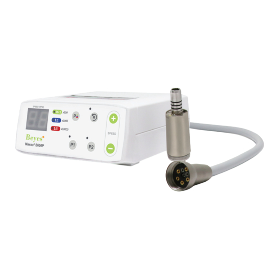
- Page 1 Maxso E600 ® Electric Micromotor System Instruction for Use...
- Page 2 Operation Manual • Equipment Classification - Class II equipment: - Type B shock protection: - Recommended sterilization: See 7. Sterilization - Do not use in the presence of flammable liquids or gases. Cautions for safe handling and operation Read these safety precautions first before using this product. These instructions will show you how to operate this product safely and prevent injury to yourself or others. They are classified by the degree and/or severity of danger. All cautions regarding safety should be observed.
-
Page 3: Specifications
Caution Unit - Grasp cord by the plug to remove from the outlet. Do not pull or yank the cord itself. It may cause the wire to malfunction. - Care should be taken not to place the AC cord near a gas burner. Never attempt to repair a burned motor cord. Always replace it with a new cord. - Prior to use, always check for vibration, noise and overheating. If any abnormalities are detected, stop using immediately and contact your dealer. - Be careful not to spill water onto the unit as it may result in a fire or an electric shock due to a short circuit. Motor, Hand piece - Do not use this product under strong stress for extended periods of time. It can cause overheating. - Do not connect or disconnect the cord until the drive motor has completely stopped. - Do not connect/disconnect the hand piece during operation. - Verify that the Speed Control Switch is adjusted within the allowable speed before use. - Connect only 4-hole, 5-hole or 6-pin tubing. - Air Requirements: Dry, free from contamination and oil. Use a compressor with a dry air system/ Install an air filter if necessary/ Blow out the lines before installation. - Do not autoclave (or any other high temperature sterilization) Control Box, AC Adaptor, Motor Code. - The user shall be responsible for operation and maintenance and inspection. 1. Specifications Model Maxso E600P Speed... -
Page 4: Component Names
2. Component Names 1. Control Box 9. Motor 2. Digital Speed Display 10. Motor Cord Gear Ratio Lamp 11. Power Switch Gear Ration Select Key 12. AC Adapter Connector 5. FWD/REV Select Key 13. Motor Cord Connector 6. Program 1 Button 14. Turbine Hose Connector Program 2 Button 15. AC Cord 8. Speed Adjusters 16. AC Adaptor... -
Page 5: Control Box Operation
3. Control Box Operation Caution Make sure there is no residual air or water in the turbine hose when connecting it to the control box. Hand tighten the nut properly without excessive force when connecting the turbine hose and the motor cord connector. 3-1 Connect the hand piece tubing from your delivery unit. Fit the turbine hose plug from the delivery unit to the turbine hose connector and tighten completely. Caution - Do not use any other hose than the ones provided with the unit - Do not use contaminated air - Blow out the lines before installation 3-2 Connecting the Motor. -
Page 6: Operation
4. Handling the Motor 4-1 Connecting/Disconnecting the motor and motor cord. Align and insert the motor pin firmly into the pin holes of the Motor Cord Motor Cord Motor Connector motor cord connector and fasten the motor cord nut securely. To remove the motor cord from the motor, unscrew and detach the motor cord nut, and gently pull out the motor cord connector. Motor Cord 4-2 Connecting/ Disconnecting the motor and hand piece To insert the E-Type hand piece into the motor, align the hand Positioning Handpiece (Option) -
Page 7: Convenient Functions
Digital Speed Display 5-4 Set the maximum speed using the Rotation Adjustment Increase Key (+/-). 5-5 Select FWD/REV rotation using the FWD/REV Select key. Decrease 5-6 The micro motor operation is controlled by the air switch/ foot pedal of the delivery unit. FWD/REV Lamp Push 6. Convenient Functions 6-1 Foot Air Calibration (unit of Display = kgf/cP By using this function, it enables you to use the maximum speed, 40,000 min^(-1)(rpm), even though the air pressure of the delivery system is not high enough, by setting the upper and lower limit of the air pressure. Notice Do this adjustment on initial set up of the unit. Once it is adjusted, it will be memorized and you won’t need to adjust again. 1) Press the P2 key and Rotation Speed Adjustment Key (+) at the same time for more than 3 seconds. 2) After the alarm sound, the indicator will change to “C1” (Lower air pressure limit setting mode) 3) By pressing the FWD/REV Rotation key, the Speed indicator will show “0.0” and “Eb” 4) Pressing on the Foot Pedal of the delivery unit will indicate the current air pressure. Notice The displayed air pressure is only a guideline. Measure the correct air pressure with the air gauge. The unit of displayed pressure is “kgf/cP ” 5) Maintain air pressure between “0.3” – “1.0”. Press the P2 Key for more than 3 seconds to memorize the lower limit of the air pressure. - Page 8 Notice - The default value is set to “0.5” - When the air pressure is not between “0.3” – “1.0”. “Eb will be shown on the display and the value will not be memorized. 6) After setting the lower limit, press the Gear Ration Select Key. The indicator will change to “C2” (Upper air pressure limit setting). 7) By pressing the FWD/REV rotation key, the indicator will show “0.0” and “Ec”. 8) By stepping on the foot pedal of the delivery system. The indicator will show the current air pres- sure. Notice The displayed air pressure is only a guideline. Measure the correct air pressure with the air meter. 9) Maintain air pressure between “2.0” – “4.0”. Press the P2 key until it beeps (more than 3 seconds) to memorize the upper limit of the air pressure. Notice The Default value is set to “3.0”. When the air pressure is not between “2.0” – “4.0” the display will show “Ec”, and the value will not be memorized. 10) Press both the P2 key and the Speed Adjustment Key (+) at the same time until you hear a beep (more than 3 seconds). When you hear the beep the setting is complete. 6-2 Light Brightness Adjustment (unit of Display = V) Brightness of the Fiber Optic can be adjusted with this function.
- Page 9 Notice Default Value is set to “3.5” Adjustable between “1.6” – “3.6”. 4) Press the P2 key until it beeps (more than 3 seconds) to the set the brightness. 5) Pres the P2 Key and the Speed Adjustment Key (+) at the same time for more than 3 seconds to leave the brightness setting. 6-3 Program Function You can store your settings into memory (Speed, Gear Ratio, Direction) and then use the P1, P2 keys to use your preferred settings. 1) Set the values for Speed, Gear Ratio, Forward/Reverse Direction. 2) Press the P1 or P2 key until you hear a beep (more than 3 seconds). When you hear the beep, the setting is complete. 7. Sterilization Sterilize the motor only. For sterilization, we recommend the autoclave sterilization method. Sterilization is required the first time you use the unit as well Autoclave Plug Tighten as after each patient as noted below. Autoclaving 1)Turn off the power. 2) Detach the motor from the motor cord. 3) Clean the surface of the motor with a brush (Do not use a Motor Cap metal brush), and wipe it with cotton and disinfectant alcohol. 4) Screw the Motor Cap to the Motor. Put the Autoclave Plug onto the motor insert. 5) Insert into autoclave ouch. Seal the pouch. 6) Autoclavable up to a maximum of 135°C. 7) Keep the Motor in the autoclavable pouch until you are ready to use it to keep it clean.
-
Page 10: Maintenance
8. Maintenance If the O-Rings become worn, the motor might not connect well to the hand piece, or water may leak. Replace the O-Rings. Changing the O-Ring Remove the O-Ring at the motor insert with a pointed tool, and mount the new O-rings into the groove. Caution There are 4 O-Rings on the Motor Insert. The blue one is thinner than the other 3. Make sure to install them in the proper spot. Caution If the O-Rings become worn, it may cause: - Air/Water leak - Difficulty attaching/disconnecting the hand piece - Excess Vibration 9. Error Codes Error Code Issue Cause Solution Overcurrent error Detected an overcurrent in the Contact your dealer (In Circuit) circuit Overcurrent error. -
Page 11: Troubleshooting
Motor start error Motor didn’t reach the preset Contact your dealer speed in the prescribed amount of time. Break down of the motor cord wire, or internal circuit malfunc- tion LED voltage error Voltage for the LED isn’t high Contact your dealer enough Air offset error Lower than preset ‘Lower limit of Displayed by foot/air air pressure” calibration function. Not a Malfunction Air full scale error Higher than preset “Upper limit of Displayed by foot/air air pressure” calibration function. - Page 12 When turned on, the setting Turned off the motor while it Do not turn off the unit until values are different from what was rotating after the motor stops spinning they were set to. 11. Beyes Limited Warranty Statement 11.1 Scope of Warranty BEYES Dental Canada Inc. (‘BEYES’) warrants to the original retail purchaser that it will be at BEYES option to repair or replace components of the dental products manufactured by BEYES (except for components not warranted under ‘Exclusions’) that are defective in material or workmanship under normal use and service. BEYES’ obligation under this limited warranty is limited to the repair or replacement of the applicable components. This limited warranty shall only apply to defects that are reported to BEYES within the applicable warranty period and which, upon examination by Beyes, prove to be defective. This warranty extends only to the first retail purchaser of a product and is not...
- Page 13 6) Costs and expenses of routine maintenance and cleaning; 7) Representations and warranties made by any person or entity other than BEYES; 8) Matching of color, grain or texture except to commercially acceptable standards; 9) Changes in color caused by natural or artificial light; 10) Custom manufactured products; 11) Alterations or modifications to the product by any person or entity other than BEYES; 12) Products that would otherwise be covered under Sections 1 and 2 of this limited warranty, but are acquired: (i) from a person or entity that is not BEYES or one of its authorized dealers; or (ii) from a BEYES dealer that is not authorized to sell the product at issue in the geographic territory where the purchaser is located, or is not authorized to sell the product at issue within the medical, animal health or dental market, as the case may be, in which purchaser intends to use the product. 11.4 Exclusive Remedy; Consequential Damages Disclaimer BEYES’ OBLIGATION UNDER THIS LIMITED WARRANTY IS THE REPAIR OR REPLACEMENT OF DEFECTIVE PARTS. BEYES SHALL NOT BE LIABLE FOR AND HEREBY DISCLAIMS ANY DIRECT, SPECIAL, INDIRECT, INCIDENTAL, EXEMPLARY OR CONSEQUENTIAL DAMAGES OR DELAYS, INCLUDING, BUT NOT LIMITED TO, DAMAGES FOR LOSS OF PROFITS OR INCOME, LOSS OF USE, DOWNTIME, COVER AND EMPLOYEE OR INDEPENDENT CONTRACTOR WAGES, PAYMENTS AND BENEFITS. 11.5 Warranty Disclaimer THIS LIMITED WARRANTY IS BEYES' ONLY WARRANTY AND IS IN LIEU OF ALL OTHER WARRANTIES, EXPRESS OR IMPLIED. BEYES MAKES NO IMPLIED WARRANTIES OF ANY KIND INCLUDING ANY IMPLIED WARRANTIES OF MERCHANTABILITY OR FITNESS FOR A PARTICULAR PURPOSE. THIS WARRANTY IS LIMITED TO THE REPAIR OR REPLACEMENT OF DEFECTIVE PARTS.
- Page 14 Federal law restricts this device to sale by or on the order of a dentist, physician, or any other practitioner licensed by the law of the states in which he or she practices to use or order the use of this device. Beyes Dental Canada Inc. is not responsible for any typographical errors. Subjects to technical changes without notice. *All brands are holders of their respective trademarks. Beyes Dental Canada Inc. 23-595 Middlefield Road Lotus NL B.V. Toronto, Ontario, P1V 3S2 Canada...
Need help?
Do you have a question about the Maxso E600 and is the answer not in the manual?
Questions and answers