Table of Contents

Related Manuals for Samson Valve Series


Summary of Contents for Samson Valve Series
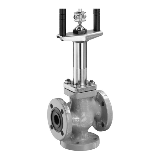
- Page 1 Valve Series V2001 Three-way Valve for Heat Transfer Oil Type 3535 Fig. 1 · Type 3535 Three-Way Valve with bellows seal and rod-type yoke (partial view) Mounting and Operating Instructions EB 8135/8136 EN Edition August 2011...
- Page 2 Safety instructions General safety instructions The valve is to be mounted, started up or serviced only by fully trained and qualified personnel, observing the accepted industry codes and practices. Make sure employees or third persons are not exposed to any danger. All safety instructions and warnings in these mounting and operating instructions, particularly those concerning assembly, start-up and maintenance, must be observed.
-
Page 3: Table Of Contents
Contents Contents Design and principle of operation....4 Technical data ......5 Installation . -
Page 4: Design And Principle Of Operation
Design and principle of operation Design principle Valve Actuator operation 3535-P Pneumatic 3371-01xx 3535-IP Electropneumatic 3372-03xx The Type 3535 Three-way Valve is con- 3535-E1 5824-30 structed on the modular assembly principle Electric and can be combined with a pneumatic or 3535-E3 3374 electric actuator as follows:... -
Page 5: Technical Data
Design and principle of operation The plug arrangement determines whether The amount of flow from A or B to AB and the three-way valve operates as mixing or vice versa is determined by the cross-sec- diverting valve. tional area between the seats and plugs. In mixing valves, the media to be mixed en- The position of the plugs (3, 3.1, 3.2) ter the valve at the ports A and B. -
Page 6: Installation
6 times the so that the plant need not be shut down for pipe diameter (DN). Contact SAMSON if maintenance routines. this length cannot be met during installation. - Page 7 Installation Mixing service Diverting service Temperature control Q = constant Flow rate control Q = 0 to 100 % Fail-safe action: FA = Actuator stem extends, FE = Actuator stem retracts Heating using a mixing valve (FA) or cooling using a mixing valve (FE) Installation in flow pipe Installation in return flow pipe Flow...
-
Page 8: Operation
Operation Operation Maintenance–replacing parts Operating instructions depend on the actua- The valve is subject to wear and tear, espe- tor used. Refer to the mounting and operat- cially at the seat, plug, bellows seal and ing instructions for the appropriate actuator. packing. - Page 9 Maintenance–replacing parts CAUTION! If you intend carrying out mainten- ance work on the valve, first depres- surize the relevant plant section and, depending on the process medium, drain it as well. Let the plant section cool down to reach ambient tempe- rature, if high temperatures prevail.
-
Page 10: Replacing The Bellows Seal
Maintenance–replacing parts Mixing and diverting valves in nominal sizes Replacing the bellows seal DN 32 to 80 differ from one another in the If the packing leaks, this is due to a dam- arrangement of their plugs and sleeves (see aged bellows seal. -
Page 11: Reassembly
Finger-tighten the coupling nut (5.1) at (12.1 and 12.2) can be ordered from first. SAMSON (see table). Insert body gasket (1.2) into the body. Especially on valves in nominal sizes DN 15 to 25, it is difficult to install the washers on 2. -
Page 12: Replacing The Seat And Plug
Maintenance–replacing parts 4. Slightly pull out the bellows housing serted in the valve. Refer to the dimen- (5.2) together with the bellows assem- sional diagram on page 23. bly. Place an open-end wrench at the Mount the actuator following the instructions side on the hexagon or the flattened part in the corresponding mounting and operat- (X) of the plug stem to hold the stem sta-... -
Page 13: Mixing Valve
Maintenance–replacing parts Carefully clean all parts and check them 4.2.1 Mixing valve for damage. Disassembly Replace defective parts with new ones. 1. Unthread stem connector nut (6.1) and 6. For valves in DN 32 and larger, remove lock nut (6.2) from the plug stem of sleeve (10.1 or 11.1). - Page 14 Maintenance–replacing parts insert a long M8 screw through the bot- Reassembly tom plug. 1. Apply lubricant (order no. 8150-0119) to the seal (5.3) and the threaded part 5. Screw top seat (2.1) into the body, en- of the bellows housing. suring that the top plug can easily slide Place seal (5.3) on the bellows housing into the seat.
- Page 15 DN 32 to 50 (12.1 and 12.2) can be ordered from Slide sleeve (10.1) over the plug stem. SAMSON (see table). Carefully place on the bonnet, while Especially on valves in nominal sizes DN 15 guiding the plug stem through the top to 25, it is difficult to install the washers on plug (3.1), sleeve (10.2) and bottom...
-
Page 16: Diverting Valve
Maintenance–replacing parts Tighten nut (12) to fasten the plug and 4.2.2 Diverting valve sleeves: Disassembly Valve DN 15 to 50 DN 65 to 80 1. Unscrew the stem connector nut (6.1) Nut (12) 15 Nm 25 Nm and lock nut (6.2) from the plug stem of valves in DN 50 or smaller. - Page 17 Maintenance–replacing parts 5. Pull the bellows assembly (5) from the Carefully clean all parts and check them bellows housing and remove body gas- for damage. If necessary, machine or ket (1.2). replace any defective parts. Clean all parts thoroughly and check Reassembly them for damage.
- Page 18 Place top plug (3.1) and four sleeves (12.1 and 12.2) can be ordered from (11.1, 11.2, 11.3, 11.4) onto the plug SAMSON (see table). stem one after the other. Especially on valves in nominal sizes DN 15 to 25, it is difficult to install the washers on 4.
- Page 19 Maintenance–replacing parts (X) of the plug stem to hold the stem Mount the actuator following the instructions stationary and to prevent the bellows in the corresponding mounting and operat- from turning. ing instructions. CAUTION! Do not turn the bellows seal. Tighten nut (12) to fasten the plug and sleeves: Valve...
-
Page 20: Tools And Tightening Torques
Maintenance–replacing parts Tools and tightening torques Valve nominal size DN 15 to 25 DN 32 to 50 DN 65 to 80 NPS ½ to 1 NPS 1½ to 2 NPS 2½ to 3 Seat wrench 1280-3010 1280-3011 1280-0305 Tool to retain 1280-3059 for washer (12.1) and lock washer (12.2) Tightening torque (±... -
Page 21: Nameplate Descriptions
Nameplate descriptions Nameplate descriptions The DIN and ANSI versions have different nameplates. DIN version Valve type Model number Model number revision index Order number or order date coefficient Nominal size Nominal pressure 11 Permissible temperature (°C) 12 Body material ANSI version Valve type Model number Model number revision index... -
Page 22: Dimensions In Mm And Inches
Dimensions in mm and inches Dimensions in mm and inches DIN version (mm) (mm) (mm) ANSI version L (in) H2 (in) H (in) Class 150 Class 300 Class 150 Class 300 ½ 7.50 3.76 9.25 ¾ 7.25 7.62 3.62 3.82 7.75 3.88 1 ½... -
Page 23: Customer Inquiries
Customer inquiries Customer inquiries Dimension applies to a plug stem inserted as far Should you have any inquiries, please sub- as it will go mit the following details: 50(1.96) Type designation and order no. (see na- meplate) Order number (see nameplate) Serial number Nominal size and valve version Pressure and temperature of process me-... - Page 24 SAMSON AG · MESS- UND REGELTECHNIK Weismüllerstraße 3 · 60314 Frankfurt am Main · Germany Phone: +49 69 4009-0 · Fax: +49 69 4009-1507 EB 8135/8136 EN Internet: http://www.samson.de...
Need help?
Do you have a question about the Valve Series and is the answer not in the manual?
Questions and answers