Samson V2001 Series Mounting And Operating Instructions
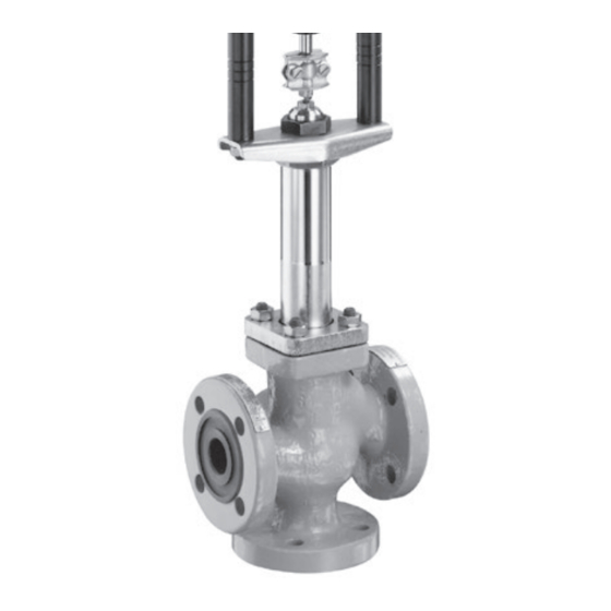
Three-way valve for heat
transfer oil
Hide thumbs
Also See for V2001 Series:
- Mounting and operating instructions (24 pages) ,
- Mounting and operating instructions (24 pages)

Related Manuals for Samson V2001 Series


Summary of Contents for Samson V2001 Series
- Page 1 Series V2001 Valves Type 3535 Three-way Valve for Heat Transfer Oil Type 3535 Three-way Valve with bellows seal and rod-type yoke (partial view) Mounting and Operating Instructions EB 8135/8136 EN Edition August 2016...
- Page 2 Definition of signal words DANGER! NOTICE Hazardous situations which, if not Property damage message or mal- avoided, will result in death or seri- function ous injury Note: WARNING! Additional information Hazardous situations which, if not avoided, could result in death or seri- Tip: ous injury Recommended action...
-
Page 3: Table Of Contents
Contents General safety instructions ................4 Design and principle of operation ..............6 Technical data ....................8 Materials .......................8 and C coefficients, seat diameters and travel ..........8 Installation ....................9 Mounting position ..................9 Arrangement of the valve ................9 Strainer and bypass ..................9 Operation ....................11 Maintenance ....................11 Replacing the bellows seal ................12 5.1.1... -
Page 4: General Safety Instructions
2014/68/EU. Valves with a CE marking have a declaration of conformity which includes information about the applied conformity assessment procedure. The declaration of conformity can be viewed and downloaded from u http://www.samson.de. − To ensure appropriate use, only use the valve in applications where the operating pres- sure and temperatures do not exceed the specifications used for sizing the valve at the or- dering stage. - Page 5 General safety instructions Note: − For installation and maintenance, make sure the relevant section of the pipeline is depres- surized and, depending on the process medium, drained as well. Depending on the field of application, allow the valve to cool down or heat up to reach ambient temperature be- fore starting any work on it.
-
Page 6: Design And Principle Of Operation
Design and principle of operation 2 Design and principle of oper- In diverting valves, the process medium en- ters at the valve port AB and the partial ation flows exit at ports A and B. The Type 3535 Three-way Valve has a mod- The flow rate from ports A or B to AB and ular design and can be combined with pneu- vice versa depends on the cross-sectional ar-... - Page 7 Design and principle of operation 10.1 10.1 10.2 10.2 10.3 10.3 12.1 12.1 12.2 12.2 Fig. 1: Sectional drawing DN 32 to 50, plug arrangement for mixing valve (left) and diverting valve (right) EB 8135/8136 EN...
-
Page 8: Technical Data
Design and principle of operation 2.1 Technical data Valve size DN 15 to 80 NPS ½ to 3 Spheroidal Stainless Spheroidal Stainless Cast steel Cast steel Material graphite iron steel graphite steel A351 1.0619 A216 WCC EN-JS1049 1.4408 iron A 395 CF8M Pressure rating PN 16 ·... -
Page 9: Installation
Î Observe the restrictions for the actuator 3.3 Strainer and bypass used. We recommend installing a SAMSON NOTICE Type 2 N Strainer upstream of the valve, and Install the valve free of stress and upstream of both inlet ports in mixing valves. - Page 10 Installation Mixing service Diverting service Temperature control Q = constant Temperature control Q = 0 to 100 % Fail-safe action: FA = Actuator stem extends, FE = Actuator stem retracts Heating with mixing valve (FA) or cooling with mixing valve (FE) Installation in flow pipe Installation in return flow pipe Flow pipe Flow pipe...
-
Page 11: Operation
Operation 4 Operation We recommend removing the parts, cleaning them, and, if necessary, replacing them with The operating instructions only apply in con- new ones. junction with the actuator. Refer to the corre- sponding mounting and operating instruc- WARNING! tions. −... -
Page 12: Replacing The Bellows Seal
Maintenance 5.1 Replacing the bellows seal housing (5.2) out of the body from above. If the packing leaks, this is due to a defective DN 32 to 80 bellows seal. In this case, the entire bellows Keep hold of the bottom plug of diverting seal assembly must be replaced together valves or the bottom sleeve of mixing with the packing (4.2). -
Page 13: Assembly
10.2 10.3 Fig. 5: Mixing valve DN 32 to 50 5.1.2 Assembly Note: Contact your nearest SAMSON sub- sidiary or the SAMSON After-sales Service department for information on suitable lubricants. 12.1 1. Apply a suitable lubricant to the gasket 12.2 (5.3) and thread on the bellows housing. - Page 14 Maintenance DN 32 to 80 9. Remove the open-end wrench. Gradually insert the plug stem of the 10. Place on the flange (5.4) and align it ready-assembly bellows seal assembly with the bellows housing (5.2), while (5) into the valve body, allowing the making sure the gasket (1.2) is correctly plugs and sleeves to slide from the screw positioned.
-
Page 15: Replacing The Seat And Plug
Maintenance 5.2 Replacing the seat and plug When replacing the seat and/or plug, we 12.1 recommend renewing the gaskets (5.3, 1.2) 12.2 at the top and bottom of the bellows housing as well. Fig. 7: Mixing valve DN 15 to 25 5.2.1 Mixing valve Disassembly 11.1... - Page 16 Maintenance 4. Unscrew the nut (12). Remove the two re- Assembly taining washers (12.2) and washer (12.1). In mixing valves DN 32 to 80, pull bot- tom sleeve (10.3 or 11.4) off the plug stem. 5. Lift the bellows housing (5.2) together with the bellows seal (5) and carefully pull the plug stem (6) out of the valve body.
- Page 17 Maintenance 6. DN 15 to 25 Insert the plug (3) into the bottom seat (2.2). 11.1 DN 32 to 50 Insert the bottom plug (3.2) into the bot- tom seat (2.2). 11.2 Place the short sleeve (10.2) and top 11.3 plug (3.1) one after the other onto the bottom plug.
- Page 18 Maintenance Slide the sleeve (10.3) onto the plug stem 12. Tighten the nut (12) to secure the plugs from underneath. and the sleeves: DN 65 and 80 Valve size 15 to 50 65 to 80 Slide the sleeve (11.1) over the plug Nut (12) 15 Nm 25 Nm...
-
Page 19: Diverting Valve
Maintenance 5.2.2 Diverting valve DN 65/80 Remove the top plug (3.1) and the four Disassembly sleeves (11.1, 11.2, 11.3, 11.4) from the valve body. 1. In valves ≤DN 50, unscrew the lock nut (6.2) and stem connector nut (6.1) from 8. DN 32 to 80 Unscrew the top and bottom seat (2.1, the plug stem. - Page 20 Maintenance Assembly the plug can slide into the seat from un- derneath. Tighten the top seat with the 1. Apply a suitable lubricant to the gasket same tightening torque. (5.3) and thread on the bellows housing. DN 32 to 50 2. Place on the gasket (5.3) and push the Insert the bottom seat (3.2) into the valve bellows seal (5) together with the plug body.
- Page 21 Maintenance hexagon (X) or at the flattened area of Valve size 65 to 80 the plug stem to hold the stem stationary. Seat thread M90 x 1.5 Tightening torque 1050 Nm NOTICE Do not twist the bellows. Place the top plug (3.1) and four sleeves (11.1, 11.2, 11.3, 11.4) onto the plug 8.
-
Page 22: Tools And Tightening Torques
Maintenance 5.3 Tools and tightening torques DN 15 to 25 DN 32 to 50 DN 65 to 80 Valve size NPS ½ to 1 NPS 1½ to 2 NPS 2½ to 3 Seat wrench with order 1280-3010 1280-3011 1280-0305 number Holding tool 1280-3059 for washer (12.1) and anti-rotation fixture (12.2) Tightening torques (±10 %) Valve seat 120 Nm (M32 x 1.5) -
Page 23: Description Of Nameplates
Description of nameplates 6 Description of nameplates The DIN or ANSI versions have different specifications on the nameplates. 6.1 DIN version Valve type Nominal pressure Model number Permissible temperature [°C] Model number index Body material Order number or date coefficient Nominal size 6.2 ANSI version Valve type... -
Page 24: Dimensions In Mm And Inches
Dimensions in mm and inches 7 Dimensions in mm and inches DIN version L (mm) H (mm) H2 (mm) ANSI version L (in) H2 (in) H (in) Class 150 Class 300 Class 150 Class 300 ½ 7.50 3.76 9.25 ¾ 7.25 7.62 3.62... -
Page 25: Customer Inquiries
Customer inquiries 8 Customer inquiries Dimension applies to plug stem pushed into Please submit the following details: the valve body − Type designation (see nameplate) 50(1.96) − Order number (see nameplate) − Serial number − Version and nominal size of the valve −... - Page 26 EB 8135/8136 EN...
- Page 27 EB 8135/8136 EN...
- Page 28 SAMSON AG · MESS- UND REGELTECHNIK Weismüllerstraße 3 · 60314 Frankfurt am Main, Germany Phone: +49 69 4009-0 · Fax: +49 69 4009-1507 EB 8135/8136 EN samson@samson.de · www.samson.de...
Need help?
Do you have a question about the V2001 Series and is the answer not in the manual?
Questions and answers